Introduction
Lithium–sulfur batteries (LSBs) with extremely high energy density (2567 Wh/kg) and theoretical capacity (1672 mAh/g) have attracted numerous attention as a promising energy storage technology.[Reference Evers and Nazar1–Reference Pang, Kwok, Kundu, Liang and Nazar3] Compared to conventional rechargeable batteries, LSBs have almost five times higher energy density thanks to the complete reaction of lithium with sulfur forming Li2S.[Reference Ji, Lee and Nazar4–Reference Pan, Han, Engelhard, Cao, Chen, Zhang, Mueller, Shao and Liu8] Nevertheless, LSBs are plagued with some problems that hinder their wide practical application. The first problem is that the sulfur is electrically insulating (5 × 10⁻²⁸ S/m), and its final discharge product of Li2S leads to poor electrochemical reaction kinetics, resulting in low active material utilization.[Reference Shim, Striebel and Cairns9,Reference Dean10] And the other problem needs to be solved is the large volume variation (approximately 80%) of sulfur during the discharge and charge processes, which naturally leads to the pulverization of active materials and severe capacity fading.[Reference Xiao, Cao, Xiao, Schwenzer, Engelhard, Saraf, Nie, Exarhos and Liu11] Moreover, diffusion of highly soluble polysulfide intermediates can also induce the sulfur shuttle mechanism and result in the irreversible changes of physicochemical properties of the electrolyte.[Reference Chung and Manthiram12,Reference Pang, Shyamsunder, Narayanan, Kwok, Curtiss and Nazar13]
The negative effects of the poor electrochemical reaction kinetics problems could be effectively reduced by combining with the conducting materials, such as graphene,[Reference Wang, Yang, Liang, Robinson, Li, Jackson, Cui and Dai14,Reference Li and Chopra15] carbon nanotubes,[Reference Li and Chopra16] conducting polymers,[Reference Wu, Chen, Chen, Wu, Li, Chen and Zhao17,Reference Yu, Xie, Li, Huang, Lai and Wang18] and other carbon matrixes,[Reference Chen, Ma, Cheng, Chen, Hu, Zhu, Wang, Liang, Tie, Liu and Jin19–Reference Li, Dykes, Gilliam and Chopra27] forming the composites. As referred to the improvement of the cycling life of the LSBs, electrolyte additives, such as LiNO3, have been demonstrated to reduce the capacity decay because the additives enhance polysulfide stability in the electrolyte, they protect the anode of lithium foil from electrochemically and chemically reaction, and they reduce the liquid electrolyte viscosity.[Reference Li and Chopra28–Reference Barchasz, Leprêtre, Alloin and Patoux30] Protecting the anode in LSBs is also an effective way to reduce the diffusion of highly soluble polysulfide intermediates and to improve the cycling performance.[Reference Zheng-Long, Kim and Kang31] Recently, it is reported that conducting polymers can contribute to the improvement of the cycling stability in LSBs thanks to the easy materials synthesis and scale-up, their robust structure that minimizes pulverization of the active materials, and they provide good electrical conductivity.[Reference Xiao, Bu, Yang, Zhang and Xu32] The preparation of composites using polymers as a substrate to load sulfur is deemed as an effective strategy for enhancing the cathode cycling stability of the LSBs.
In this work, a unique brush-structured composite of sulfur–polyaniline–graphene (S–PANI–G) was designed and synthesized. PANI–G was designed and synthesized by the direct polymerization of aniline on graphene oxide (GO).[Reference Marcano, Kosynkin, Berlin, Sinitskii, Sun, Slesarev, Alemany, Lu and Tour33–Reference Xu, Wang, Zu, Han and Wei35] GO was not only served as a substrate to grow PANI but also used to enhance the stability of PANI.[Reference Hu, Tu, Jiao, Hou, Zhu and Fray36,Reference Li, Zhao, Yu and Zhang37] S–PANI–G was synthesized by the heat treatment of PANI–G and elemental sulfur. In S–PANI–G, PANI–G serves as an electronically conductive framework for the sulfur loading and a matrix to trap the elemental sulfur and soluble polysulfide intermediate via efficient physical and chemical adsorption. Moreover, PANI–G plays a role as a buffer to the volume variation occurred in the cycling processes. S–PANI–G as the cathode material demonstrates the excellent electrochemical performance. It demonstrates that the stable reversible discharge capacity can reach 1000 mAh/g at a rate of 0.1 C and only suffers a small capacity decay after 100 cycles at 0.4 C. Therefore, S–PANI–G is a superb candidate for use as LSBs cathode materials.
Experimental
Synthesis of PANI–G
GO was prepared using the improved Hummers method.[Reference Marcano, Kosynkin, Berlin, Sinitskii, Sun, Slesarev, Alemany, Lu and Tour33] PANI–G was synthesized by the direct polymerization of aniline on GO. In a typical procedure of PANI–G, GO (40 mg) was dissolved into 1 M aq. H2SO4 (80 mL) and then the mixture went through an ultrasonication process to form a uniform GO solution. 1.8 g of aniline was added to the GO solution, and the obtained mixture was continuously stirred to uniformity for 20 min in a NaCl-ice bath. 1.1 g of ammonium persulfate oxidant was dissolved in 1 M aq. H2SO4 (80 mL) and kept 10 min in a NaCl-ice bath. Then, the above two solutions were mixed together and stirred for 6 h in a NaCl-ice bath. And then, the resultant solution was processed via vacuum filtration and washed with deionized water and ethanol. Lastly, PANI–G (242 mg) was obtained after a 12 h-drying process in a vacuum oven at 80 °C and 4.0-inch Hg.
Synthesis of S–PANI–G
A certain amount of sulfur (400 mg) was added into carbon disulfide (2 mL). 80 mg of PANI–G composite was added to the solution and stirred for 30 min using magnetic stirring. And then, the obtained mixture was loaded into a 50 mL Pyrex ampule, which was purged with N2 for three times, and then, the ampule was sealed with acetylene torch under vacuum (0.05 Torr). Then, the two-step heat-treatment process was conducted. In the first step, the sample was first treated at 155 °C, where it remained for 12 h. In the second step, the sample was further heated up to 280 °C with a soaking time of 12 h to finish the vulcanization reaction. The product S–PANI–G was collected after the reaction cooled to room temperature (RT).
Materials characterization
Characterization of microstructure, element composition, and morphology of specimens were conducted on x-ray diffraction analysis (XRD; Max Ultima II), scanning electron microscopy (SEM; Hitachi SU-8030), x-ray photoelectron microscopy (XPS; PHI Quantera), transmission electron microscopy (TEM; JEM-2100F), and thermal gravimetric analyzer (TGA; TA Instruments Q50), respectively.
Electrochemical measurements
Cathode materials were prepared by mixing the S–PANI–G composite (80 wt%), carbon black (Super P, 10 wt%), and polyvinylidene difluoride (Alfa Aesar, 10 wt%) in N-methyl-2-pyrrolidone (NMP) forming a slurry, which was coated on an aluminum foil substrate. And electrochemical experiments were conducted by using CR2032 coin-type cells. The electrolyte was 1 M lithium bis(trifluoromethane) sulfonamide dissolved in a mixture of 1,3-dioxolane and dimethyoxyethane (1:1 by volume), and the separator was a Celgard 2300 membrane. Cyclic voltammetry (CV) measurements were conducted using a CHI660D electrochemical station. Electrochemical impedance spectroscopy (EIS) experiments were conducted on a CHI660D at the open circuit potential in a 100 kHz–10 mHz frequency. Moreover, the measurement of galvanostatic discharge–charge experiments was conducted using a LAND CT2001A battery system at RT.
Results and discussion
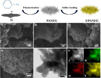
The scheme of the construction of S–PANI–G nanocomposite is depicted in Fig. 1. GO and aniline were mixed to form a uniform suspension, and the aniline was absorbed on the surface of the GO, forming active nucleation sites. PANI grew outward from the surface of the GO after the addition of ammonium persulfate to the solution. PANI was thus obtained on the GO by the direct polymerization of aniline. PANI–G with brushed structure was dispersed in a carbon disulfide solution with elemental sulfur forming a complex powder after solvent evaporation. S–PANI–G was obtained after a two-step heat treatment in the sealed vessel filled with nitrogen.
Schematic illustration of the synthesis of S–PANI–G: (a and b) SEM images of PANI–G under different resolution; (c and d) SEM images of S–PANI–G at different resolutions; (e) STEM images of S–PANI–G; and (f) corresponding elemental mapping of carbon, nitrogen, oxygen, and sulfur.

The characterization of the morphology of S–PANI–G and PANI–G was performed by SEM and STEM. Figures 1(a) and 1(b) depict the morphology of PANI–G at low and high resolutions. It can be observed that the vertically aligned PANI with the ordered structure could be observed on the sheets of GO. After the sulfur loading, the morphology of PANI on the surface of GO was well maintained [Figs. 1(c) and 1(d)]. Evidence for the structure was supported by the STEM images [Fig. 1(e)]. Figure 1(f) demonstrates that the as-prepared S-PANI–G composite mainly contains four kinds of elements, including carbon, sulfur, nitrogen, and a trace amount of oxygen. And the emergence of oxygen is likely to stem from ammonium persulfate and sulfuric acid.
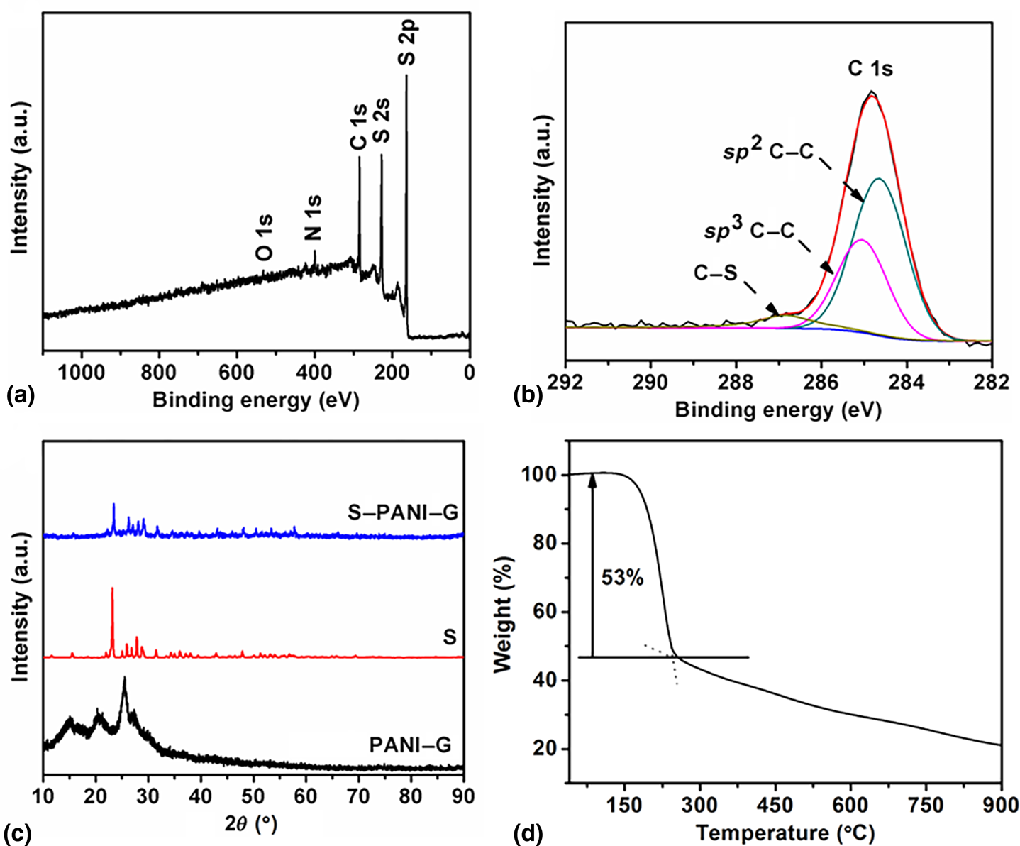
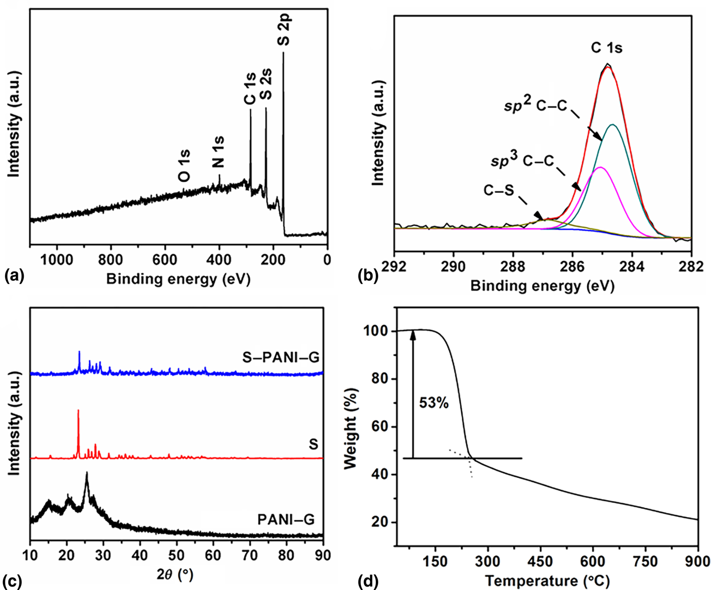
XPS and XRD were also employed to study S–PANI–G. Figure 2 presents the XPS spectrum and XRD pattern of specimens. Figure 2(a) demonstrates that the nanocomposite of S–PANI–G is composed of sulfur, carbon, nitrogen, and a trace amount of oxygen, which might result from ammonium persulfate and/or sulfuric acid. In Fig. 2(b), the peaks located at a binding energy of 284.5, 284.8, and 286.8 eV are clearly observed, corresponding to the sp 2 hybridized C, sp 3 C–S, and C–S chains,[Reference Pascal, Villaluenga, Wujcik, Devaux, Jiang, Wang, Balsara and Prendergast38] respectively. Figure 2(c) exhibits the XRD data of S–PANI–G composite, sulfur, and PANI–G. It can be clearly seen that the PANI–G presents four diffraction peaks at 15.0°, 20.6°, 25.4°, and 27.0°,[Reference Li, Zheng, Lu, Hu, Shen, Chang, Ji, Cao and Shi39,Reference Li and Chopra40] respectively. The S–PANI–G nanocomposite presents a similar XRD pattern with sulfur, excluding the typical PANI–G peak because the strong sulfur peaks overlap with the characteristic peaks of PANI–G in the composite. TGA was used to evaluate the sulfur amount loaded in the obtained composite. The TGA curve shows that the composite possesses 53% sulfur content, as depicted in Fig. 2(d).
(a) C 1s core-level XPS spectra; (b) XPS survey spectrum of S–PANI–G; (c) XRD patterns of sulfur, PANI–G, and S–PANI–G; and (d) TGA curve of S–PANI–G recorded in an argon atmosphere at a heating rate of 5 °C/min.
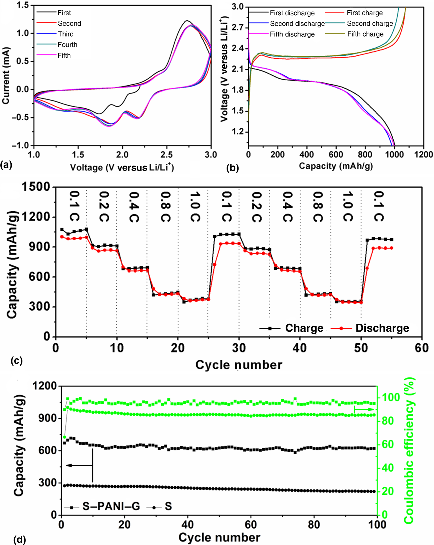
To investigate the electrochemical reaction mechanism of S–PANI–G cathode in the LSBs, the CV test was conducted in the potential ranging from 1.0 to 3.0 V. As presented in Fig. 3(a), three cathodic peaks at 2.18, 1.86, and 1.27 V (versus Li/Li+) during the cathodic reduction process can be observed. It is reported[Reference Yang, Yu, Cha, Wu, Vosgueritchian, Yao, Bao and Cui41] that the reduction process of sulfur to higher-order polysulfides leads to a cathodic peak ~2.18 V, resulting from the reaction mechanism of sulfur in the cycling processes. And the peaks at 1.86 and 1.27 V result from the sulfur reduction from the higher-order polysulfides to lower-order polysulfides, Li2S2, and Li2S. Moreover, after the first cycle, two stable oxidation peaks, which are located at 2.41 and 2.78 V, are exhibited. The two oxidation peaks are attributed to the conversion among Li2S, sulfur, and polysulfides. The characteristics of the CV area of peaks exhibit little change except for the first cycle. This demonstrates the relatively good capacity retention of the S–PANI–G cathode in LSBs. Figure 3(b) shows the voltage versus capacity of S–PANI–G at 0.1 C. It is obvious that the stable, reversible discharge capacity is over 1000 mAh/g in the first five cycles. There are three plateaus of the cathode in the discharge curves, which is related to the formation of higher-/lower-order polysulfides and Li2S. Obviously, the result of voltage measurement is in agreement with the data of CV measurement.
(a) First five CV of the composite S–PANI–G at a sweep rate of 0.4 mV/s; (b) the discharge and charge voltage versus specific capacity profiles at 3.0–1.0 V at 0.1 C; (c) rate performance of S–PANI–G at various rates from 0.1 to 1.0 C with respect to the cycle numbers; and (d) cycling performance of S–PANI–G at the rate of 0.4 C.

The rate performance of the S–PANI–G is shown in Fig. 3(c). Stable capacity at different current rates ranging from 0.1 C to 1.0 C to 0.1 C was exhibited. The capacity value of S–PANI–G almost fully recovered when the rate was reduced from a high rate of 1.0 C to a low rate of 0.1 C. The rate performance exhibits that S–PANI–G was stable after the prolonged cycles. And at the same, while the cycling performance of S-PANI-G was evaluated [Fig. 3(d)]. The discharge capacity is 604 mAh/g at the first cycle and increases to 692 mAh/g at the second cycle. One could observe that the discharge capacity decreased slightly when the cycle number was increased. It reached 600 mAh/g at the 20th cycle. This might arise from the loss of sulfur at the surface of S–PANI–G. During the subsequent cyclic process, the discharge capacity keeps stable and reaches 590 mAh/g at the 100th cycle, and there was only a capacity decay of 1.66% occurred during the 80 cycles after the 20th cycle. S–PANI–G had the good coulombic efficiency performance. It quickly increased to almost 100% in the second cycle. Then, it slightly decreased but maintained at ~97%. At the same, while the discharge capacity of the sulfur control sample exhibits a value of 256 mAh/g at the second cycle and decreases to 188 mAh/g at the 100th cycle, with a coulombic efficiency of 85%. Based on the result, it can be deduced that PANI–G effectively traps the polysulfide during the cycling process and restrains the shuttle effect, leading to the improvement of the cycling performance combined with the high coulombic efficiency of the LSBs.
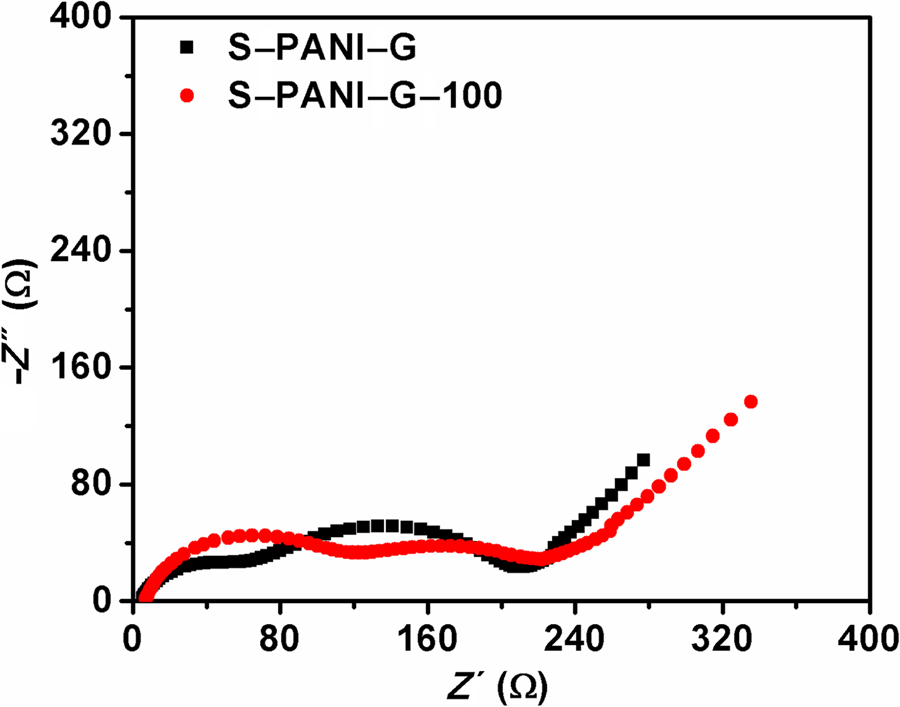
EIS experiments were done on a fresh S–PANI–G electrode and S–PANI–G after 100 cycles (S–PANI–G-100), and the related equivalent circuit model was established (Fig. 4; Supplementary Fig. S1). As shown in Fig. 4, the plots are composed of two semicircles and a straight line. And the semicircles mainly rise from the transport of Li+ through the passivation film (R p), as well as the interfacial charge-transfer process (R ct) combined with the electrochemical capacitive behavior constant phase element and C dl. The straight line with a slope of approximately 45° is corresponding to the Li+ diffusion in the cathodes (Z w). Supplementary Table S1 presents the impedance parameters calculated based on the equivalent circuit. After 100 cycles, R s of S–PANI–G was increased from 4.41 to 5.55 Ω, which resulted from the viscosity increase of the electrolyte solution generated from the dissolution of the intermediate lithium polysulfide.[Reference Zu, Su, Fu and Manthiram42] The decrease of R ct from 110.90 to 63.94 Ω implies that the electronic conductivity of the composite S–PANI–G was improved to some degree. This may result from the loss of the outer layer sulfur in the composite after certain discharge–charge processes. The increase of R p from 79.45 to 160.10 Ω is due to the irreversible formation of Li2S on the cathode.[Reference Balach, Jaumann and Giebeler43] This change led to the capacity decay of the S–PANI–G in the LSBs.
Nyquist plots of S–PANI–G before and after 100 cycles.

Conclusions
To sum up, in this work we successfully designed and constructed a brush-structured nanocomposite of S–PANI–G. Electrochemical experiments demonstrate that S–PANI–G exhibits satisfying rate performance, high capacity, as well as promising cycling stability as LSBs cathode materials, thanks to the synergic effect among PANI, GO, and sulfur. S–PANI–G shed light on the improvement of the electrochemical performance and stability of the cathode materials used for the LSBs.
Supplementary material
The supplementary material for this article can be found at https://doi.org/10.1557/mrc.2019.149.
Acknowledgments
This research was partly supported by the project funded by the China Postdoctoral Science Foundation (No. 2018M643698) and the National Natural Science Foundation of China (No. 51802258).