INTRODUCTION
Focusing and transport of space-charge-dominated, hundreds of kilo-Amperes, ion beams are challenging problems, because the strong repulsive Coulomb force between ions leads to rapid expansion of the beam envelope. This space charge phenomenon is an important issue in a large number of applications, including proton-based fast ignition, heavy-ion fusion drivers, isochoric heating of matter in high energy density laboratory plasma experiments, particle cancer therapy, etc (Roth et al., Reference Roth, Cowan, Key, Hatchett, Brown, Fountain, Johnson, Pennington, Snavely and Wilks2001; Reference Roth, Blazevic, Geissel, Schlegel, Cowan, Allen, Gauthier, Audebert, Fuchs and ter Vehn2002; Reference Roth, Alber, Bagnoud, Brown, Clarke, Daido, Fernandez, Flippo, Gaillard, Gauthier, Geissel, Glenzer, Gregori, Günther, Harres, Heathcote, Kritcher, Kugland, LePape, Li, Makita, Mithen, Niemann, Nürnberg, Offermann, Otten, Pelka, Riley, Schaumann, Schollmeier, Schütrumpf, Tampo, Tauschwitz and Tauschwitz2009; Patel et al., Reference Patel, Mackinnon, Key, Cowan, Foord, Allen, Price, Ruhl, Springer and Stephens2003; Bartal et al., Reference Bartal2011; Henestroza et al., Reference Henestroza, Logan and Perkins2011; Yang et al., Reference Yang, Ma, Shao, Xu, Yu, Gu, Yu, Yin, Tian and Kawata2010; Borghesi et al., Reference Borghesi, Sarri, Cecchetti, Kourakis, Hoarty, Stevenson, James, Brown, Hobbs, Lockyear, Morton, Willi, Jung and Dieckmann2010; Romagnani et al., Reference Romagnani, Borghesi, Cecchetti, Kar, Antici, Audebert, Bandhoupadjay, Ceccherini, Cowan, Fuchs, Galimberti, Gizzi, Grismayer, Heathcote, Jung, Liseykina, Macchi, Mora, Neely, Notley, Osterholtz, Pipahl, Pretzler, Schiavi, Schurtz, Toncian, Wilson and Willi2008). Beam collimation, which is a special case of focusing, is also needed for density radiography or injection into a transport lattice of a conventional accelerator.
Presently, the common technique to focus an ion beam is based on applications of externals magnetic or electric fields, generated by solenoids, quadrupoles, radio frequency systems, plasma lenses, etc. (Harres et al., Reference Harres, Alber, Tauschwitz, Bagnoud, Daido, Gunther, Nurnberg, Otten, Schollmeier and Schtrumpf2010; Nishiuchi et al., Reference Nishiuchi2010; Basko et al., Reference Basko, Drozdovskii, Golubev, Gubskii, Iosseliani, Kantsyrev, Karpov, Kuznetsov, Novozhilov, Pronin, Savin, Sasorov, Sobur, Sharkov and Yanenko2008; Tauschwitz et al., Reference Tauschwitz, Boggasch, Hoffmann, Jacoby, Neuner, Stetter, Stöwe, Tkotz, De Magistris and Seelig1995; Seidl et al., Reference Seidl, Anders, Bieniosek, Barnard, Calanog, Chen, Cohen, Coleman, Dorf, Gilson, Grote, Jung, Leitner, Lidia, Logan, Ni, Roy, Van den Bogert, Sefkow, Waldron and Welch2008; Ter-Avetisyan et al., Reference Ter-Avetisyan, Schnürer, Polster, Nickles and Sandner2008). In this paper, we evaluate the technical feasibility of a novel passive focusing technique, which makes use of the beam's self-generated magnetic field. The physics prerequisite of the concept is straightforward: as a non-neutralized charged particle beam propagates in vacuum, it interacts with its self-generated fields: defocusing electric field, E, and focusing magnetic field, B (see Eq. (1)). In vacuum, the electric repulsing force is always stronger than the magnetic one. The excessive electrostatic force together with the emittance contributes to transverse expansion of the beam. If the electrical force is attenuated (or neutralized) then the beam is self-focused by the magnetic force.
 $$\eqalign{&F_E \lpar r\rpar =qE\lpar r\rpar =\displaystyle{{qI\lpar r\rpar } \over {2{\rm \pi} vr}}\comma \; \cr & F_B \lpar r\rpar =- qvB\lpar r\rpar =- \displaystyle{{q{\rm \mu} _0 vI\lpar r\rpar } \over {2{\rm \pi} r}}\comma \; \cr &\left\vert {\displaystyle{{F_B } \over {F_E }}} \right\vert =\displaystyle{{v^2 } \over {c^2 }}={\rm \beta} ^2 .}$$
Although the described principle seems straightforward, so far there is no convincing experimental confirmation of the phenomena with heavy ion beams. This phenomenon is very well-known in the beam physics of electrons: an electron beam, which usually has v ≈ c, does not expand, due the favorable F B/F E relation. In addition, utilizing thin conducting surfaces to passively focus a particle beam has been analyzed and experimentally demonstrated for electrons (Fernsler et al., Reference Fernsler, Hubbard and Slinker1990; Humphries et al., Reference Humphries, Ekdahl and Woodall1989; Adler, Reference Adler1982). In this case, semi-transparent metal meshes are employed in place of foils. Numerous schemes to focus ion beams using fine conducting wires, meshes, and other structures to attenuate the defocusing self electric field, and/or utilizing plasma to produce neutralization, have been proposed in the community; many of these were associated with studies in collective ion acceleration (Olson & Schumacher, Reference Olson and Schumacher1979; Seidl et al., Reference Seidl, Anders, Bieniosek, Barnard, Calanog, Chen, Cohen, Coleman, Dorf, Gilson, Grote, Jung, Leitner, Lidia, Logan, Ni, Roy, Van den Bogert, Sefkow, Waldron and Welch2008). In general, little documentation of these ideas is available and situation is even worse with finding the documented experimental outcomes. Recently, foil focusing for heavy ions and protons using the stack of a conductors has been proposed by B.G. Logan (Lawrence Berkeley Laboratory seminar, October 26, 2010) to focus a heavy ion beam to a small spot, for the purpose of igniting the X-target (Henestroza et al., Reference Henestroza, Logan and Perkins2011) in heavy-ion fusion and various fast ignition and warm dense matter applications. This paper has been triggered by the work of Henestroza et al. (Reference Henestroza, Logan and Perkins2011) and B.G. Logan (Lawrence Berkeley Laboratory seminar, October 26, 2010) and its primary motivation is investigation of technical feasibility of experiments in which a clear experimental evidence of the self-focusing phenomena with heavy ion can be demonstrated.
The outline of this paper is as follows. First, physics of the concept is described; second, justification for the target-normal-sheath-acceleration (TNSA) protons (Snavely et al., Reference Snavely2000; Hatchett et al., Reference Hatchett, Brown, Cowan, Henry, Johnson, Key, Koch, Langdon, Lasinsky and Lee2000; Borghesi et al., Reference Borghesi2004; Flippo et al., Reference Flippo, Hegelich, Albright, Yin, Gautier, Letzring, Schollmeier, Schreiber, Schulze and Fernández2007; Brambrink et al., Reference Brambrink, Roth, Abel Blazevic and Schlegel2006) as the best candidate for the proof of principle experiments; third, technical feasibility study is presented, followed by a robust target design for the near term validation experiments.
PRINCIPLE
The discussed approach to attenuate the electrical field is based on a well-known phenomenon: as a charged particle beam propagates between two closely spaced, conducting planes, separated by an insulator (later referred to as a “gap”), the planes charge up with image charges of an opposite sign. The induced electric field from the image charges, E im, is opposite to that of the beam, E, thus reduces the net field; meanwhile the magnetic self-field, B, of the beam remains unaffected by the conductors. The strength of this canceling E-field is determined by the distance between planes: a smaller distance results in a stronger field. The E-field attenuation produced by one pair of conductors is often not sufficient to produce a significant focusing (especially if the ions have an initial defocusing radial momentum) — the cancellation of the beam's self-electric field should be maintained for a distance long enough for the self-magnetic field to produce noticeable focusing. In practice, this can be implemented by placing (stacking) multiple conducting foils (later referred to as lens) in the beam path with the distance between foils determining the effective focusing strength of such a lens.
Conductors are also essential to prevent ion beam current neutralization by the co-moving “knock-on” electrons produced during collisions of ions with a conductor. If not removed, the co-moving electrons neutralize the ion current thus weaken the magnetic field and the self-focusing. The absorbed electrons accumulate at the conducting plates and may disturb the charging induced by the beam. This excessive charge can be removed by grounding each conductor.
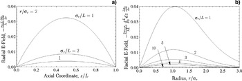
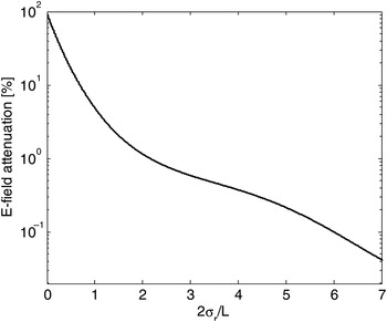
Precise analytical derivation of the electric field and the resulting beam envelope, in which the self-electric defocusing force is calculated for self-similarly evolving density profiles using Green's function, are extensively covered in an accompanying paper by Lund et al. (Reference Lund, Cohen and Ni2012). Strength of the net electrical field, a sum of the image charge field and self-field, is determined by the aspect ratio between transverse size of the beam and longitudinal distance between planes, L (from here on we assume a Gaussian transverse ion beam profile, with a beam radius equal to 2σ r; furthermore, σ r/L is defined as the aspect ratio). In summary, the longitudinal electrical field has a bell shape distribution (Fig. 2a); it is zero at the conductors and reaches maximum in the middle of the gap. Along the radial direction, the field increases with a distance and reaches a maximum at the edge of the beam (Fig. 2b). Figure 3 shows attenuation of the E-field relative to the vacuum value — when no conductors are present — versus σ r/L. The electrical field diminishes non-linearly with increasing ratio: the field is reduced to a quarter of its vacuum value when the distance between foils equals beam diameter and becomes negligible, less than a percent, when the distance is 1/8 of the beam radius. An important implication of Lund's calculations is that, since a typical radius of an ion beam ranges from hundreds of micrometers to several millimeters, significant field attenuation can be achieved with macroscopic distances between foils.
Axisymmetric beam between two, thin conducting foils located at z =± L/2. The foils are grounded. As a beam propagates between two closely spaced, conducting planes, separated by an insulator (vacuum), the planes charge up with image charges. An electric field, E im induced by this charge, is opposite to that of the beam, E and cancels it out; the magnetic self-field, B of the beam remains unaffected by the conductors, thus allowing for a pinch.

Longitudinal (a) and transverse (b) net E-field distribution between conducting planes shown for various beam-to-foils space aspect ratios (Lund et al., Reference Lund, Cohen and Ni2012). The transverse profile is shown for the middle point between conductors, z = 0. For a reference, electrical field strength without conductors (2σr/L = 0) is 0.4.

Relative strength of the net electric field between conductors versus aspect ratio. 100% corresponds to un-attenuated electrical field when no conductors are present 2σr/L = 0). The attenuation curve is shown for ions in the mid point of the gap, x = 0, at a 2σ distance from beam axis.

APPLICATION TO TNSA PROTONS
Among various types of ion beams available for the validation of the described technique, TNSA proton beams are the most suitable candidates. First, the kilo-Ampere levels of electrical currents, typical for TNSA beams, are already sufficient to generate strong magnetic fields (Lund et al., Reference Lund, Cohen and Ni2012). Second, emittance of the TNSA beam (ɛ ≤ 0.1π mm mrad) is remarkably low for a typical high current ion beam. According to our literature survey, the “high” emittance of ion beams plausibly has been one of the major reasons preventing experimental demonstration of the concept with ion beams (Olson & Schumacher, Reference Olson and Schumacher1979). Third, high TNSA proton energies (1 MeV–50 MeV) lead to a more favorable magnetic-to-electric-force ratio, which scales as β2 (Eq. (1)). In addition, MeV-energy protons can propagate with relatively low distortion through micrometer thick foils, making target manufacturing simpler and target handling easier. Lastly, since the number of knock-on electrons, generated during collisions of charged particles with a conductor scales as Zion2, the unfavorable beam neutralization is least possible in experiments with protons (Hubbard et al., Reference Hubbard, Goldstein and Tidman1979). Among major drawbacks of the TNSA beams that can prevent an observation of the phenomena are large energy spread (up to 100%), large beam divergence (10°–20° half angle), and beam distortion (energy loss and scattering).
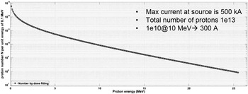
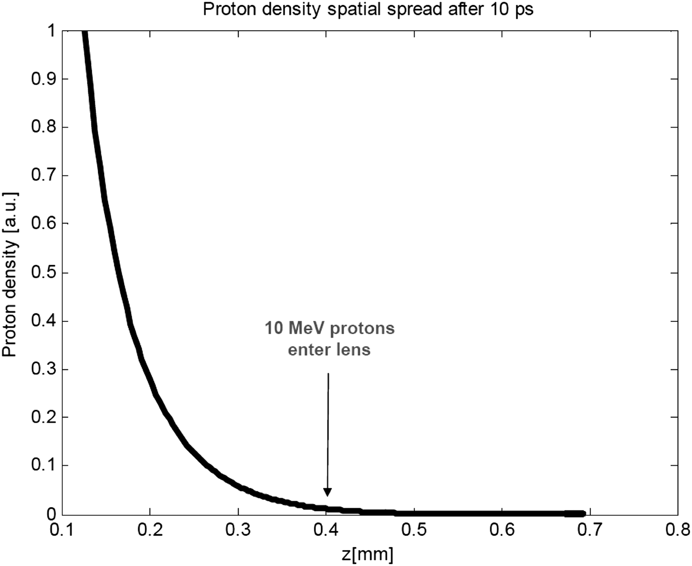
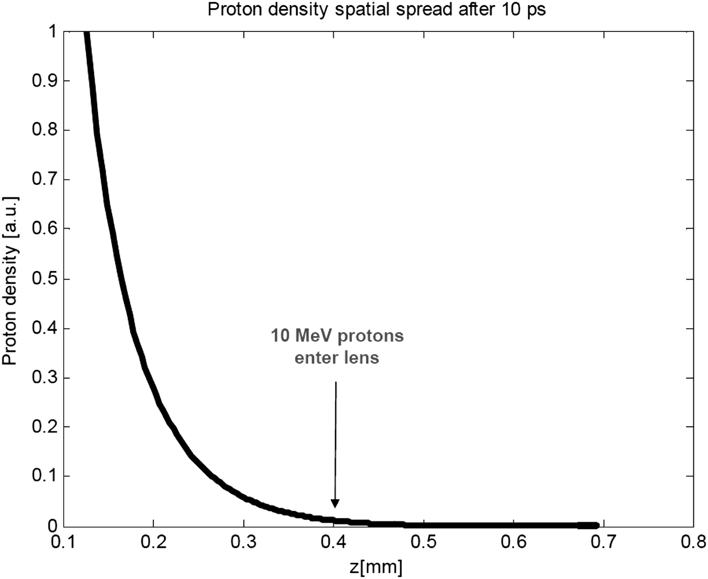
A typical TNSA proton beam has about 5 ps, full width at half maximum pulse duration, and an energy spectrum with a sharp exponential distribution (Figure 9) (Snavely et al., 2000; Hatchett et al., Reference Hatchett, Brown, Cowan, Henry, Johnson, Key, Koch, Langdon, Lasinsky and Lee2000; Borghesi et al., Reference Borghesi2004). Due to the broad energy range, protons of different energies arrive at the lens entrance at different times (Fig. 5). As a result, an instant electrical current in the lens depends on proton energy, leading to chromatic aberrations — protons of different energies are focused unequally and at different points. In the preliminary estimate, which assumes an initially collimated beam and 100% electric field neutralization, it was determined that, for example, a 25 MeV-energy protons (I~3 A) from the high-energy part of the spectrum, can be focused in about 300 mm distance, while, less energetic but more intense, 1 MeV-energy protons (I~300 kA), can be focused in a about 30 mm distance. Such a large spread in the focal distances makes the design of an achromatic lens overly complex. For the initial proof-of-principle experiments, it is preferred to design simpler lens that is tuned for a narrow energy spectrum. Having analyzed various energies between 1 MeV and 20 MeV, the 10 MeV-energy protons (I~400 A) are chosen as the base-line energy. These protons have sufficient current to pinch within a reasonable distance, require a technically feasible distance between conductors and number of conductors, and arrive at the lens before it gets destroyed be preceding protons (see more explanation below).
Typical proton spectrum generated by PHELIX-GSI laser via TNSA mechanism.

A spatial spread of 5 ps proton bunch at the moment, when the base-line, 10 MeV, protons enter the lens (positioned 0.4 mm away from the source). High-energy proton, arriving earlier, slightly pre-heat Al foils; low energy protons have sufficient energy to evaporate foils.
PROOF-OF-PRINCIPLE EXPERIMENTS
In a typical TNSA experiments, a proton beam is generated by illuminating a 5 µm–10 µm-thick, flat gold foil with an intense laser beam (100 fs–500 fs pulse duration, 10 J–100 J energy per pulse, average laser power about 1018 W/cm2) focused to >20 µm spot (Snavely et al., 2000; Hatchett et al., Reference Hatchett, Brown, Cowan, Henry, Johnson, Key, Koch, Langdon, Lasinsky and Lee2000; Borghesi et al., Reference Borghesi2004). A typical divergence of 10 MeV protons generated with a flat source foil is about 20° (half angel). As the TNSA proton beam propagates from a source foil, it is space-charge-neutralized by the electrons generated during the TNSA process and expands ballistically. Upon entering the lens, all the co-moving neutralizing electrons are stripped at the first foil and the proton beam becomes space-charge-dominated. At this stage the only force that can contain the beam is the self-magnetic force from the beam current. However, since the ions already possess a large transverse momentum (due to the large divergence), the magnetic force must first overcome the outward proton motion before it can start focusing the beam inward. The magnetic force is proportional to the current density, which is at its highest value when a lens is positioned to the source as close as possible. The closest distance that does not perturb the TNSA mechanism is about 0.5 mm, which for the 10 MeV protons corresponds to 2σ r~200 µm beam radius at the entrance of the lens. In this case, the ratio between electric and magnetic forces at the entrance of the lens is approximately 50:1. According to Figure 3, the 1:1 ratio (a collimation case, when E-field equals B-field) can be achieved when 2σ r/L = 2, which corresponds to L~100 µm. Gap sizes less then this threshold value will result in the pronounced focusing.
The finite longitudinal extension of the proton bunch imposes limitation on the distance between conductors: for the optimal E-field neutralization, the beam must fill the entire space between conducting planes (Fig. 1). A simple estimate shows that a 5 ps, 10 MeV beam has about 400 µm length. The later number is thus a reliable estimation of the upper limit of distance between two neighbor conductors and does not interfere with the earlier 100 µm distance estimate necessary for the 1:1 ratio.
A careful analysis, presented in greater details in Lund et al. (Reference Lund, Cohen and Ni2012), reveals a major issue that requires modifications of the TNSA flat-foil proton source. According to beam envelope calculations, beam divergence, as large as a fraction of a degree, results in a substantial increase in the focal length, even with complete E-field attenuation. The number of conductors, required to maintain the attenuation at these longer distances, exceeds the permissible number (estimated later). The 20° divergence of 10 MeV is far above the divergence threshold derived in Lund et al. (Reference Lund, Cohen and Ni2012), making the observation of the pinch phenomena highly unlikely. At the same time, the same analysis shows that a slight inward focusing greatly aids the magnetic field, leading to a pronounced pinch at shorter distances.
One way to address the large divergence is to use a curved source foil (hemisphere shape), which is a well-known technique to focus a TNSA proton beam (Patel et al., Reference Patel, Mackinnon, Key, Cowan, Foord, Allen, Price, Ruhl, Springer and Stephens2003). A small focal spot (about Ø20 µm) is desired in most applications, in which such a curved source foil is used. It is achieved with a hemisphere of a radius ranging from 100 µm to 160 µm. Meanwhile, in the “stack foil” setup, such a strong focusing is undesirable because it will lead to premature destruction of the lens. A proton source that will satisfy requirements of the proposed experiment must produce a collimated or slightly inward focused beam. Theoretically, such beams can be generated by hemispheres with R >160 µm. However, as the most of the experiments have been requiring strong focusing, there is no information available on the performance of hemisphere sources with R >200 µm. Up to date, the only available reference, is a PIC-code simulation (Bellei et al., Reference Bellei, Foord, Bartal, Key, McLean, Patel, Stephens and Beg2012) that demonstrates that a 10 µm thick, 300 µm radius hemisphere would produce a nearly collimated Ø75 µm diameter proton beam at about 400 µm distance from the source. Since there are no other references on the performance of a 300 µm radius source, results of this simulation are considered as the initial beam conditions at the entrance of the lens in the following lens design.
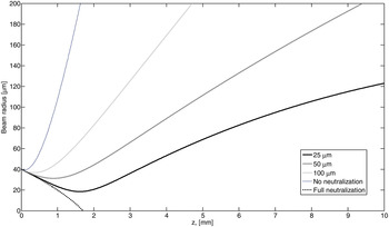
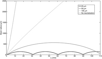
The beam envelopes for the three different constant spacing, 25 µm, 50 µm, and 100 µm, are shown for a proton beam with the initial beam conditions from Bellei et al. (Reference Bellei, Foord, Bartal, Key, McLean, Patel, Stephens and Beg2012). While, in practice, the gap size can have any value, these spacing are chosen to represent three typical cases. The 25 µm gap leads to a strong E-field attenuation (short focus) and indefinite beam confinement, which consists of periodic focusing and defocusing of the beam. The 50 µm spacing provides less attenuation, which results in a longer focal length, but still makes it possible to contain the beam. The 100 µm distance does not provide enough E-field cancellation to focus the beam and can only decelerate the space-charge driven expansion. For a reference, beam envelopes with a fully neutralized E-field and space charge dominated beam (i.e., no conductors) are also shown in the plots.
The beam envelopes estimates, shown in Figures 6 and 7, are idealized and do not consider scattering, full energy spectrum, finite length of the beam, etc; also the number of foils is unlimited. More precise beam envelope calculations and computer simulations that include some of these effects are partially covered in Lund's paper and match the data in Figures 6 and 7 within about 20%. This accuracy is sufficient for narrowing down design parameters for the initial experiments, in which any measurable spot-size-reduction is sufficient to prove the principle.
Estimates of beam envelope inside a lens with different distances between conductors. For a reference, beam envelopes with a fully neutralized E-field and space charge dominated beam (no conductors) are shown.

Estimates of beam envelope inside a lens with different distances between conductors (zoomed out).

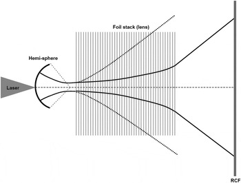
The E-field cancellation phenomena can be robustly observed by comparing radius in experiments with and without a lens (called a “reference” experiment) as it is schematically explained in Figure 8. For example, if a radio-chromic-film, a standard technique to measure beam profile in TNSA experiments, is placed 10 mm away from the source, diameter of the beam in the reference experiments is about 2 mm, while diameters in experiments with the various lenses are 120 µm, 200 µm and 400 µm (correspond to 25 µm, 50 µm, and 100 µm spacing, respectively) — a several folds difference that can be easily detected. Moreover, even the relative difference among experiments with various gap sizes, although less sensitive, is still large enough to be measured. The number of foils required for these initial proof of experiments, depending on the gap size, ranges from 100 to 400.
Scheme of a proof-of-principle experiments (not to scale). Dashed beam envelope represents the reference experiment, in which no lens is used and the beam expands ballistically.

CONSIDERATIONS FOR THE LENS CONSTRUCTION
In this section, we discuss the hardware characteristics that can fulfill the physics requirement determined in the previous section.
In general, a “conducting plane” is a high conductivity and low inductance structure, such as a metal foil, metal mesh, carbon-fiber array, a slice of metal foam, etc. Al is an obvious choice of the material, since it is easy to handle, it is a light-weight conductor, and has the lowest energy loss and hence largest penetration range — long range is critical when a large number of conductors must be used. Al is also a favorable material from the radioactive activation safety point of view. Furthermore, since the number of knock-on electrons scales linearly with atomic number, Zfoil, Al, due its low Zfoil, will generate the least number of electrons (Hubbard et al., Reference Hubbard, Goldstein and Tidman1979), thus a lens made of aluminum will have less of the beam neutralization issue. The second best material option is carbon, which is mechanically more robust but has worse conductivity and higher energy loss.
Al is also a suitable material for the lens fabrication using a chemical etching process, a possible procedure for thin foil production. The chemical etching process has been demonstrated recently at TU-Darmstadt (G. Schaumann, private communication, 2011) to fabricate stacks of about 1 µm thick Al foils separated by gaps with >20 µm between adjacent foils, and with about 10 mm characteristic transverse extent. Another approach to fabricate a lens is to stack washers with Al-foils glued on each washer. The foils are pre-cut from a larger piece; thickness of a washer determines the gap size. Initial assembly tests by General Atomics indicate that construction of such a target is possible (N. Alexander, private communication, 2012). Because the main purpose of the foils is to attenuate the radial electric field, alignment tolerances (tilts, offsets, distortions) are not anticipated to be demanding so long as neighboring foils do not touch.
As discussed earlier, for the strongest image charge field, the size of a conductor must be much larger than the beam diameter. Considering the anticipated beam dimensions in Figure 7, foils larger than 5 mm will ensure that weakening effect of the fringe filed, occurring at the edges of a foil, is negligible. Thickness of the foil is a compromise: it must be sufficiently thin to minimize the beam distortion, such as scattering and energy loss, but at the same it must be sufficiently thick so that a foil is mechanically stable and can absorb all the co-moving electrons. The thinnest available freestanding metal foil is about 50 nm. Nevertheless, at least a 0.5 µm thick Al foil is necessary to stop 100 keV knock-on electrons (energy of knock-on electrons is not known; conservatively, if one assumes that a 10 MeV proton transfers a small fraction of its energy, then the energy of electrons should not exceed few hundreds of keV).
The maximum number of foils is limited by the distortion of the beam. The penetration range of a 10 MeV proton in solid Al is about 650 µm (SRIM, 2012): the deposition rate is low and quasi-constant (0.8 keV/μm) for the first 500 µm of propagation, followed by an exponential increase, which peaks at 650 µm. For a reference, 1300 foils (0.5 µm-thick) will absorb the beam entirely, while1000 foils will absorb about 0.4 MeV (4%) — an insignificant beam distortion. Hence an upper limit of foil layers is between 1000 and 1500. For simplicity, in the future references, 1000 foils can be used as a robust upper limit.
Lateral straggling, or scattering, is another effect that affects the proton beam and in addition to space-charge and emittance, it can be considered as an additional “force,” contributing to the expansion of the proton bunch. According to TRIM, lateral straggling in a single, 0.5 µm thick, foil is about 5 nm, which corresponds to a about 0.1° divergence (SRIM, 2012). The net scattering of a proton beam in an Al plate, thickness of which is equivalent to 1000 foils stacked together, is about 40 µm, corresponding to about 4.5°. This distortion would cause a noticeable broadening of an otherwise unperturbed beam and should be accounted in a lens design. Meanwhile, the effect of scatterings is less of an issue in the initial proof of principle experiments, as the expansion of the beam caused by straggling is still much smaller than the expansion of a beam in the reference experiment, in which no lens is present.
Preliminary estimates indicate that total energy contained in a TNSA proton bunch (Fig. 4) is sufficient to evaporate foil material along the path of the beam, making the lens a single-shot component. Due to the finite distance, between source and the lens and broad energy spread, different energies will arrive at different times (Figure 8) thus allowing for a time window, during which the base-line, 10 MeV protons can propagate through an undamaged stack. Considering the known values of Al heat capacity, dE/dx and proton energy spectra in Figure 3, it is possible to estimate the temperature of foils at different moments of time. Summarized, all the protons between 10 MeV and 20 MeV contain energy sufficient to slightly pre-heat a foil to tens of degrees. For a reference, 1010, base-line 10 MeV, protons deposit roughly 0.5 µJ in each foil, resulting in several degrees temperature increase. Arriving later, the low energy, high intensity protons (N~1013) will heat up a foil to a plasma state, T > 1 eV. With the sound speed at a few km/s, a hydro-expansion time of a 0.5 µm thick foil is about 200 ps. For a comparison, it would take about 10 ns for the Al plasma to expand and fill in the smallest 25 µm design gap between conductors. At the same time, it takes about 300 ps for the entire proton bunch to propagate through a 10 mm long lens. Since the time-of-flight though the lens is close to the hydro-response time, the low energy protons will propagate through hot plasma at a near solid state density in a warm-dense-matter state. Conductivity of warm-dense-matter is lower than that of cold matter, but it is much larger than that of an insulator. The exact warm-dense-matter conductivity is not known, but plausibly it may be sufficient to generate image charge to focus the high intensity part that was not considered initially. Further investigations, based on WDM simulations, are needed, but in overall the initial estimates suggest that in the future due to the short-pulse nature of the processes, it might be possible to focus a broader energy spectrum of the TNSA proton beam — an achromatic proton lens.
Finally, an electrostatic case has been considered here, meaning that the image charge can form instantaneously. In reality, the time for a charge within a foil to respond to the external electrical field is finite, and if the pulse duration is much shorter than the response time, then the image charge will not accumulate in time, reducing the effectiveness of the E-field cancellation. The fastest response time of electrons in a typical conductor (n e = 1021) is determined by the plasma frequency which is equal to 2π/ωp~10−3 ps. This response time is noticeably less than the 5 ps bunch duration and thus justifies the electrostatic treatment.
DISCUSSION
According to Lund et al. (Reference Lund, Cohen and Ni2012) the theoretical limit of a focal spot size of a lens with constant pattern of foil spacing is about 50 µm. For a contrast, an estimate of emittance limited spot performed in Patel et al. (Reference Patel, Mackinnon, Key, Cowan, Foord, Allen, Price, Ruhl, Springer and Stephens2003) is about 1 µm. The large discrepancy can be explained by the non-optimal, constant spacing pattern between conductors: as the beam gets focused, aspect ratio changes unfavorably, resulting in less of E-field attenuation. Clearly, a progressively decreasing gap size is needed in order to keep the E-field attenuation (or aspect ratio) at the same constant level. Hence, in future work, focal spots smaller than those quoted in Patel et al. (Reference Patel, Mackinnon, Key, Cowan, Foord, Allen, Price, Ruhl, Springer and Stephens2003) can be plausibly achieved with an alternating, adaptive gap-size pattern, so that the attenuation of the electrical field (aspect ratio) is maintained at a constant rate.
A noticeable distortion of a beam in 0.5 µm Al foils is one of the key factors that determine a maximum number of foils. While, the degree of distortion is sufficient for the proof of principle-experiments, future lens optimizations will have to explore thinner conductor options, such as carbon fiber based foils, metal foams, etc. The thickness of Al can be further trimmed if the energy of knock-on electrons were known more accurately: the 100 keV is an overly conservative estimate. Hence, future experiments and simulations should concentrate on more precise estimates of the energy of the knock-on electrons. Further upgrades that can potentially improve performance of a lens include usage of ferromagnetic material and application of external magnetic fields (Lund et al., Reference Lund, Cohen and Ni2012).
An extensive three-dimensional simulation, which includes full spectrum of the beam, ion scattering, electron neutralization, finite length of the beam, is needed for both the interpretation of near term experiments and a design of a lens tailored to a specific application. Additionally, a simulation that considers warm-dense-matter aspect of foils, such as hydro-expansion and electrical conductivity, is necessary to develop an achromatic lens that can focus a broad spectrum of proton energies.
Finally, the described technique is not limited to only the TNSA protons. TNSA protons are a platform for demonstration of the principle, intended to stimulate application of the technique to other types of ion beams.
SUMMARY
TNSA protons have been considered as a promising candidate to demonstrate the E-field cancellation phenomenon of an intense ion beam using a stack of conducting foils. A robust point design for the near term experiments consists of a few hundred, aluminum, 0.5 µm thick foils with gap sizes ranging from 25 µm to 100 µm. High divergence of TNSA beam requires, pre-collimation of the beam, which can be achieved with a curved source foil. A lens with these specifications as well as a curved source foil is within manufacturing capabilities of modern target fabrication labs. Experiments with the robust target design are the first step towards controlled focusing of ions with a stack of conductors.
ACKNOWLEDGMENTS
Author would like to thank Joe Kwan (LBNL), Christopher McGuffey (UCSD), Claudio Bellei (LLNL), Andy Faltens (LBNL), and Oliver Deppert (TU-Darmstadt) for the fruitful technical discussions. This research was performed under the auspices of the U.S. Department of Energy at the Lawrence Berkeley and Lawrence Livermore and National Laboratories under contract numbers DE-AC02-05CH11231 and DE-AC52-07NA27344. Finally, the authors sadly note the untimely passing of our friend, colleague, and co-author Frank Bieniosek. His clarity of scientific vision, his energy and enthusiasm, his guidance, and his companionship are much missed.