Introduction
Nuclear energy has become a reliable type of baseload power to provide constant and carbon-free electricity, and it currently meets 10% of the world’s energy demands.1 Nuclear power produces nearly 20%, 80%, and 18% of the electricity in the United States, France, and Russia, respectively, and about 2.5% in China. Structural alloys in nuclear applications, where they are subject to radiation by energetic particles (e.g., alpha and beta particles, fission fragments, and neutrons), suffer over time from damage and properties degradation. Advanced structural alloys that can withstand radiation are a pressing need. The predictive discovery and guided design of advanced structural materials with targeted functionalities are key to enabling modern technologies, especially for future nuclear energy applications.
Until quite recently, the pursuit of metallic alloys with increased structural strength or improved radiation performance has relied on incorporating a large number of defect sinks to mitigate radiation-induced damage, through either alloying elements at low concentrations (solutes, which interact with matrix/solvents) to form so-called dilute alloys or creating nanoscale features.Reference Brailsford, Bullough and Hayns2–Reference Mansur and Lee4 Some of these conventional alloys may contain high concentrations of alloying elements and were originally developed as extensions of dilute alloys.
More than a decade ago, a new paradigm in alloy design—complex concentrated alloys (CCAs), composed of multiple elements all at high concentrations—has emerged that presents unforeseen opportunities for materials discovery.Reference Yeh5,Reference Miracle and Senkov6 In sharp contrast to dilute alloys existing near the corners of phase diagrams, CCAs are formed near the centers of phase diagrams. All the multiple principal elements do interact with each other in the matrix that is different from the solutes and dismisses the difference between solvents and solutes.Reference Cantor7 Among CCAs, single-phase concentrated solid-solution alloys (SP-CSAs), composed of two to five (or more) elements, in many cases at or near equiatomic composition, have drawn great attention.Reference Wu, Bei, Otto, Pharr and George8,Reference Zhang, Stocks, Jin, Lu, Bei, Sales, Wang, Béland, Stoller, Samolyuk, Caro, Caro and Weber9
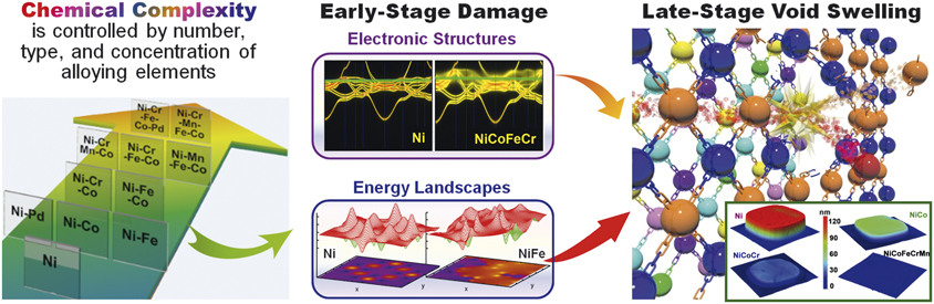
In SP-CSAs, the elements randomly distribute on simple underlying face-centered-cubic (fcc) or body-centered-cubic (bcc) lattice sites. SP-CSAs are a unique group of CCAsReference Yeh5,Reference Miracle and Senkov6 that have tunable chemical complexityReference Zhang, Stocks, Jin, Lu, Bei, Sales, Wang, Béland, Stoller, Samolyuk, Caro, Caro and Weber9,Reference Zhang, Zhao, Weber, Nordlund, Granberg and Djurabekova10 but lack microstructural inhomogeneities (e.g., nanoclusters, secondary phases, grain boundaries, interfaces).Reference Beyerlein, Caro, Demkowicz, Mara, Misra and Uberuaga3,Reference Mansur and Lee4 High-entropy alloys (HEAs), a subset of SP-CSAs, commonly contain five or more elemental species. An example of the tunable chemical complexity, increasing from pure nickel (Ni) to HEAs (NiCrFeCoMn and NiCrFeCoPd), is shown in Figure 1 on the large background arrow. To highlight the impact of chemical complexity on the dissipation of radiation energy, this article focuses on SP-CSAs that do not present complications resulting from microstructural inhomogeneities.
Single-phase concentrated solid-solution alloys (SP-CSAs) are alloys with tailored chemical complexity tunable via the intrinsic elemental disorder. The chemical complexity may be tuned by increasing the number of multiple principal elements (from 1 to 5, shown from the lower left to the upper right corner in the background arrow), by replacing the principal elements (e.g., in the ternaries of NiCrCo and NiFeCo by replacing Cr with Fe), and by modifying the concentration in the alloys (e.g., from Ni0.5Fe0.5 to Ni0.7Fe0.3 or Ni0.9Fe0.1, or varying concentration of all elements of 20 ± 5% in quinternaries of NiCoFeCrMn and NiCoFeCrPd). The tunable chemical complexity (e.g., left: a subset of SP-CSAs) represents a powerful tool for dramatically modifying properties at the level of electrons and atoms (middle: electronic structure and energy landscapes in pure nickel and CSAs) and ultimately enhancing radiation tolerance (right: schematic drawing of an atomic collision and the radiation-induced swelling from step-height measurements).

To design structural materials for advanced nuclear applications, some prime challenges in materials science need to be addressed. How do remarkable properties of matter emerge from complex correlations of the atomic or electronic constituents, and how can we control these properties? How do we control materials processes at the level of electrons and atoms; and how do we characterize and control matter away—especially very far away—from equilibrium?11 One approach to moving beyond current knowledge and incremental property improvements in conventional alloys is to identify and understand the roles of all constituents in the structural stability of the alloys and their effects on energy dissipation mechanisms at the level of electrons and atoms.
CCAs and CSAs are currently a topic of rapidly rising research interest, and SP-CSAs are unique model systems to tackle the challenges. As an example of tunable chemical complexity, a progression in compositional complexity shown in Figure 1 (left) from elemental Ni to quinternary SP-CSAs—including the corresponding Ni–based binary, ternary, and quaternary subsystems—offers a powerful means to explore the influences of energy dissipation and defect energetics on defect production and recombination, as well as mass transport. Understanding and optimizing the chemical complexity both locally and globally in SP-CSAs can enable the tailoring of energy dissipation and defect evolution resulting from individual radiation events to encourage defect annealing within the picosecond time scale.Reference Zhang, Stocks, Jin, Lu, Bei, Sales, Wang, Béland, Stoller, Samolyuk, Caro, Caro and Weber9,Reference Zhang, Zhao, Weber, Nordlund, Granberg and Djurabekova10,Reference Zhao, Egami, Stocks and Zhang12 For example, the ability to tailor the chemical complexity of SP-SCAs can be used to control energy dissipation via energy carriers that transport charge, heat, and spin (Figure 1, top center) (e.g., little smearing in pure Ni implies long electron mean free path, whereas smearing throughout the electronic band structure in NiCoFeCr implies a mean free path on the order of the interatomic spacing that profoundly reduces thermal conductivity)Reference Zhang, Stocks, Jin, Lu, Bei, Sales, Wang, Béland, Stoller, Samolyuk, Caro, Caro and Weber9 and to modify the energy landscape (Figure 1, bottom center) (e.g., in contrast to isotropic defect energy landscape in Ni, the landscape in NiFe is rougher, creating local traps, and anisotropic diffusion channels) in order to control defect evolution resulting from kinetic energy transfer and mass transport during and after radiation events (e.g., collision cascades and defect migration).Reference Osetskiy, Beland, Barashev and Zhang13,Reference Granberg, Nordlund, Ullah, Jin, Lu, Bei, Wang, Djurabekova, Weber and Zhang14 Manipulation of a material’s ability to dissipate radiation energy can control the early stages of defect formation and mass transport and subsequently impact the evolution of defects in later stages, which may ultimately suppress damage accumulation under prolonged high-dose irradiation (Figure 1, right) (e.g., suppressed void swelling in order of highest to lowest from Ni, NiCo, NiCoCr and NiCoFeCrMn at elevated temperatures).Reference Zhang, Zhao, Weber, Nordlund, Granberg and Djurabekova10,Reference Lu, Niu, Chen, Jin, Yang, Xiu, Zhang, Gao, Bei, Shi, He, Robertson, Weber and Wang15
Understanding the chemical complexity that arises from intrinsic elemental disorder in SP-CSAs is fundamental to understanding alloy performance in extreme environments. Here, recent advances reported in the literature are reviewed from five main aspects, starting at the level of electrons and atoms: electronic effects, atomic effects, and coupled electronic and atomic effects to defect evolution and microstructure progression. This article aims to highlight unique defect properties and microstructural evolution in SP-CSAs under both thermal equilibrium and nonequilibrium (radiation) conditions, which will guide the design criteria to intrinsically drive recovery from the damaged state.
Dissipation of radiation energy in concentrated solid-solution alloys
The interaction of energetic electrons, ions, and neutrons with solids initiates energy-transfer processes in both the electronic and atomic subsystems; neither electronic nor atomic effects should be overlooked. Nuclear energy loss results in displacement damage and defect cluster formation, while energy transferred to the target electrons creates high electronic temperatures and instabilities that may lead to defect annealing or clustering. Local electronic and atomic environments have a strong impact on radiation defect evolution. One of the biggest challenges in radiation-induced defect science is to understand the complex nature of such coupled electronic and atomic effects under extreme conditions. The dissipation of radiation energy in and its impact on CSAs can be summarized as follows.Reference Zhang, Stocks, Jin, Lu, Bei, Sales, Wang, Béland, Stoller, Samolyuk, Caro, Caro and Weber9,Reference Zhang, Zhao, Weber, Nordlund, Granberg and Djurabekova10,Reference Zhao, Egami, Stocks and Zhang12–Reference Wang, Jin, Chen, Bei, Wang, Weber, Zhang and More52
1. Electronic effectsReference Zhang, Stocks, Jin, Lu, Bei, Sales, Wang, Béland, Stoller, Samolyuk, Caro, Caro and Weber9,Reference Jin, Sales, Stocks, Samolyuk, Daene, Weber, Zhang and Bei16–Reference Mu, Yin, Samolyuk, Wimmer, Pei, Eisenbach, Mankovsky, Ebert and Stocks18 —Electrons, magnons, and electronic structure affect energy transfer and defect properties. The d electron characteristics have been shown to control the defect properties of SP-CSAs composed of 3d transition metals (3d SP-CSAs). A substantial reduction in the capability to dissipate energy with increasing differences in the 3d electron count (Figure 1, top center) is demonstrated, and more localized heat is shown to enhance defect recombination.
2. Atomic effectsReference Warren19–Reference Zhang, Zhuang, Hu, Kai and Liu32—Complex energy landscapes can significantly affect defect migration and atomic transport. Because of the complex chemical disorder (Figure 1, left) in CSAs, defects have been shown to experience a complex energy landscape (Figure 1, bottom center) that affects transport properties and defect behavior. A wide distribution of defect energetics and chemically biased mass transport resulting from chemical disorder have been revealed. The high atomic-level stresses and modified atomic motion facilitate rapid annealing and prevent growth of extended defects.
3. Coupled electronic and atomic effectsReference Zhang, Stocks, Jin, Lu, Bei, Sales, Wang, Béland, Stoller, Samolyuk, Caro, Caro and Weber9,Reference Granberg, Nordlund, Ullah, Jin, Lu, Bei, Wang, Djurabekova, Weber and Zhang14,Reference Jin, Sales, Stocks, Samolyuk, Daene, Weber, Zhang and Bei16–Reference Mu, Yin, Samolyuk, Wimmer, Pei, Eisenbach, Mankovsky, Ebert and Stocks18,Reference Ullah, Artacho and Correa34–Reference Sellami, Debelle, Ullah, Christen, Keum, Bei, Xue, Weber and Zhang39 —Pronounced ionization effects alter atomic processes, modify defect dynamics, and affect microstructure evolution. A clear impact of electronic and ionic energy exchange on defect production and evolution has been demonstrated. More pronounced coupling effects are observed in more complex SP-CSAs because of lower thermal conductivity and stronger electron–phonon (e-ph) coupling, compared with Ni or dilute alloys.Reference Zarkadoula, Samolyuk, Xue, Bei and Weber36–Reference Sellami, Debelle, Ullah, Christen, Keum, Bei, Xue, Weber and Zhang39
4. Defect evolutionReference Zhang, Stocks, Jin, Lu, Bei, Sales, Wang, Béland, Stoller, Samolyuk, Caro, Caro and Weber9,Reference Zhang, Zhao, Weber, Nordlund, Granberg and Djurabekova10,Reference Zhao, Egami, Stocks and Zhang12,Reference Osetskiy, Beland, Barashev and Zhang13,Reference Lu, Niu, Chen, Jin, Yang, Xiu, Zhang, Gao, Bei, Shi, He, Robertson, Weber and Wang15,Reference Mu, Samolyuk, Wimmer, Troparevsky, Khan, Mankovsky, Ebert and Stocks17,Reference Mu, Yin, Samolyuk, Wimmer, Pei, Eisenbach, Mankovsky, Ebert and Stocks18,Reference Jin, Zhang, Zhang and Bei40–Reference Yang, Lu, Velisa, Jin, Xiu, Crespillo, Zhang, Bei and Wang47 —Local chemical disorder affects phase stability, radiation-induced segregation, and microstructure evolution. Chemical complexity has been shown to be a unique tool to intrinsically suppress damage evolution under irradiation. The underlying mechanisms of how chemical disorder alters the processes of kinetic energy, heat, and mass transport in SP-CSAs have been uncovered.Reference Zhang, Stocks, Jin, Lu, Bei, Sales, Wang, Béland, Stoller, Samolyuk, Caro, Caro and Weber9,Reference Zhang, Zhao, Weber, Nordlund, Granberg and Djurabekova10,Reference Zhao, Egami, Stocks and Zhang12,Reference Osetskiy, Beland, Barashev and Zhang13,Reference Mu, Samolyuk, Wimmer, Troparevsky, Khan, Mankovsky, Ebert and Stocks17,Reference Barashev, Osetsky, Bei, Lu, Wang and Zhang41
5. Microstructure progressionReference Lu, Niu, Chen, Jin, Yang, Xiu, Zhang, Gao, Bei, Shi, He, Robertson, Weber and Wang15,Reference Barashev, Osetsky, Bei, Lu, Wang and Zhang41,Reference Lu, Yang, Niu, Peng, Jin, Crespillo, Velisa, Xue, Zhang, Xiu, Zhang, Gao, Bei, Weber and Wang46–Reference Wang, Jin, Chen, Bei, Wang, Weber, Zhang and More52 —Complex chemical disorder delays microstructure degradation, retards void swelling, and suppresses helium (He) bubble growth. Tuning defect energetics and chemical complexity significantly suppresses the growth of extended defects and detrimental voids or He bubbles in SP-CSAs.
Electronic effects
Recent research on electronic effects provides a rich picture of how ions and electrons interact when they are under equilibrium or driven out of equilibrium by energetic particles. Knowledge of the electronic structure and magnetic characteristics of 3d SP-CSAs and their element-based temperature-dependent intrinsic properties has provided critical insights into energy dissipation processes.
Modified electronic structure due to magnetic frustration: Orders-of-magnitude reductions in electron mean free paths and localized electron–electron interactions can be achieved by controlling alloying complexity, ranging from single element to binary, ternary, quaternary, and quinternary SP-HEAs (Figure 1, left).Reference Zhang, Stocks, Jin, Lu, Bei, Sales, Wang, Béland, Stoller, Samolyuk, Caro, Caro and Weber9,Reference Jin, Sales, Stocks, Samolyuk, Daene, Weber, Zhang and Bei16,Reference Mu, Samolyuk, Wimmer, Troparevsky, Khan, Mankovsky, Ebert and Stocks17 For alloys containing only iron, cobalt, and nickel, the majority-spin channel experiences negligible electron scattering, thereby providing low electrical resistivity.Reference Zhang, Stocks, Jin, Lu, Bei, Sales, Wang, Béland, Stoller, Samolyuk, Caro, Caro and Weber9,Reference Mu, Samolyuk, Wimmer, Troparevsky, Khan, Mankovsky, Ebert and Stocks17 In contrast, for alloys containing chromium and manganese, strong electron scattering occurs in both spin channels, leading to high electrical resistivity.Reference Zhang, Stocks, Jin, Lu, Bei, Sales, Wang, Béland, Stoller, Samolyuk, Caro, Caro and Weber9,Reference Mu, Samolyuk, Wimmer, Troparevsky, Khan, Mankovsky, Ebert and Stocks17 Figure 2 shows Fermi surfaces of majority- and minority-spin channels (i.e., spin-up and spin-down electrons) for high-resistivity NiFeCoCrMn and low-resistivity NiCo alloys, respectively.Reference Mu, Samolyuk, Wimmer, Troparevsky, Khan, Mankovsky, Ebert and Stocks17 While the electron mean free path for NiCo is short for the minority-spin electrons, it is large for the majority spin electrons, thereby providing a short circuit and an overall low resistivity. On the contrary, for NiFeCoCrMn, both channels are smeared, implying a short mean free path in both spin channels. The resultant strong electron scattering can, therefore, lead to a high residual resistivity. For the nonmagnetic Ni0.8Cr0.2 and NiCoCr alloys, the combined effects of chemical disorder and electron-lattice vibration scattering result in a monotonic increase in the resistivity as a function of temperature from an already large residual resistivity at 0 K.Reference Mu, Samolyuk, Wimmer, Troparevsky, Khan, Mankovsky, Ebert and Stocks17 For magnetic NiCo, NiFe, and NiFeCo, all with small residual resistivity, additional electron scattering from temperature-induced magnetic moment fluctuations results in a further rapid increase in the resistivity with increasing temperature.
Fermi surfaces (Γ-Χ-W plane in arbitrary units) of majority- and minority-spin channels in NiCo and NiFeCoCrMn alloys, respectively. The spin channels are distinguished using ↑ and ↓.Reference Mu, Samolyuk, Wimmer, Troparevsky, Khan, Mankovsky, Ebert and Stocks17

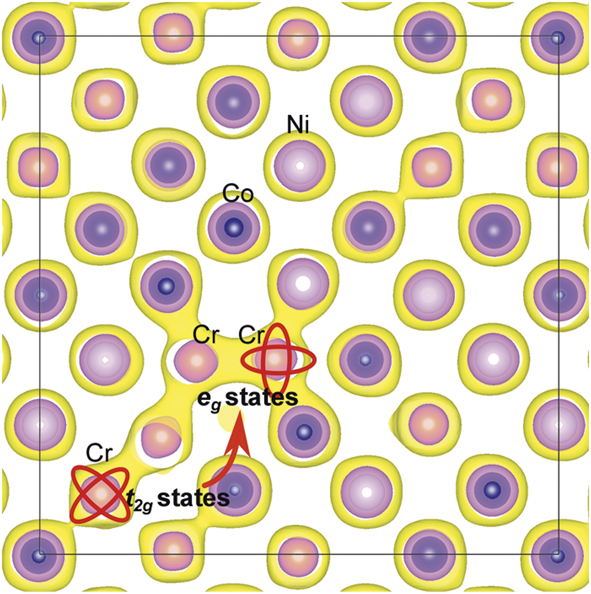
d electrons govern transport and defect properties: The d electron characteristics affect electronic transport,Reference Zhang, Stocks, Jin, Lu, Bei, Sales, Wang, Béland, Stoller, Samolyuk, Caro, Caro and Weber9,Reference Jin, Sales, Stocks, Samolyuk, Daene, Weber, Zhang and Bei16,Reference Mu, Samolyuk, Wimmer, Troparevsky, Khan, Mankovsky, Ebert and Stocks17 magnetic signatures,Reference Mu, Yin, Samolyuk, Wimmer, Pei, Eisenbach, Mankovsky, Ebert and Stocks18 and defect propertiesReference Zhao, Egami, Stocks and Zhang12 of SP-CSAs composed of 3d transition metals. In complex SP-CSAs, the distribution of electronic density or the density of active valence electrons is no longer uniform. Analysis of electronic structures reveals that the electronic deformation (the capability for charge transfer between neighboring atoms) resulting from partially filled d electrons, and the number of active valence electrons, are key to understanding defect energetics.Reference Zhao, Egami, Stocks and Zhang12 Compared with late 3d transition elements (i.e., Ni, Co), the partially filled d electrons and their densities in Fe and Cr are flexible (e.g., t 2g to eg transition, Figure 3) to readily accommodate defects, resulting in a beneficially wide distribution of their migration energies (see discussion of defect annihilation in the section on “Defect evolution” and Figure 11).
Electron density contour plot showing that a Cr interstitial defect in NiCoCr induces transition from the t 2g(σ) orbital extending along [111] to the e g(π) orbital extending along [100] of Cr electronic states. For defect-free Cr atoms, t 2g states—shown as a diagonal elongation of electronic density—are dominant. Introduction of a Cr interstitial leads to a transition to e g states (along axial directions). This electron deformation capability is attributed to partially filled electrons of Cr compared with Ni/Co.Reference Zhao, Egami, Stocks and Zhang12

Further study revealed the hidden Mn magnetic-moment disorder and its influence on the physical properties.Reference Mu, Yin, Samolyuk, Wimmer, Pei, Eisenbach, Mankovsky, Ebert and Stocks18 A ground state in fcc NiCoMn was uncovered, which distinguishes two equally populated Mn components with large spin moments (disordered local moments), but opposite orientations. This ground state was further demonstrated to be the most energetically favorable in the presence of spin noncollinearity between averaged moments on different sites. These findings reflect the importance of magnetic signatures for the physical properties of SP-CSAs and suggest a path forward to study magnetism-controlled electronic structure and energy dissipation.
Atomic effects
In SP-CSAs, extensive chemical disorder and elemental diversity result in rich atomic-level inhomogeneities. Composition fluctuation in SP-CSAs at the atomic level calls attention to the short-range order and highlights the necessity for fully interpreting correlations among all chemical elements, as the scenario of a totally random arrangement is insufficient. Atomic movements and thermodynamic defect stability depend on local environment and temperature. Understanding atomic effects provides an opportunity to verify the electronic effects on defect stabilization and reveal that atomic-level distortion directly affects defect properties. A link between the local atomic arrangement and temperature-dependent structural stability in chemically complex SP-CSAs has been established, offering a basis for predicting and engineering local structural stabilities by tailoring the local atomic arrangement.
Local lattice distortion: Local lattice distortion exists in SP-CSAs, even though the average lattice remains undistorted. The extent of local lattice distortion has been investigated and determined both experimentally and from modeling work.Reference Warren19–Reference Zhang, Zhao, Jin, Xue, Velisa, Bei, Huang, Ko, Pagan, Neuefeind, Weber and Zhang21
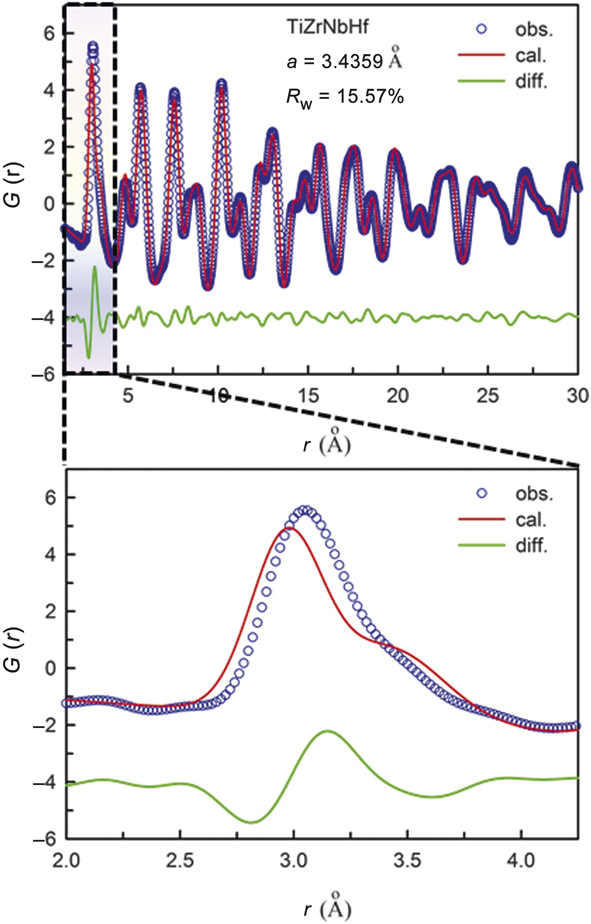
In x-ray diffraction measurements of CSAs, the average lattice structure produces sharp Bragg diffraction peaks just as a perfect crystal does, whereas local distortions produce diffuse scattering in between the Bragg peaks. The local atomic displacements have two components, thermal displacement that depends on temperature and local distortion that does not change with temperature. Measurements of the total scattering, include both the Bragg peaks and diffuse scattering. The total structure function, S(Q), which is the normalized diffraction intensity corrected for the atomic scattering factor and other effects, such as absorption, can be Fourier-transformed to obtain the atomic pair distribution function (PDF), G(r), which depicts the distribution of distances between atoms, including local distortions.Reference Warren19,Reference Egami and Billinge20 An example of the PDF is shown in Figure 4 for bcc TiZrNbHf CSA.Reference Tong, Zhao, Bei, Egami, Zhang and Zhang22 The calculated PDF assumes random atomic displacements, as in the Debye–Waller factor, and fits the measured PDF beyond 4 Å. As shown in Figure 4, the calculated PDF fails to explain the first and second peaks, suggesting locally correlated atomic displacements exist within the second neighbors. The effect is less pronounced for the fcc lattice, which is close-packed. In the bcc lattice (not close-packed), chemical disorder plays havoc on the local structure.
The pair-distribution function (PDF) of body-centered-cubic TiZrNbHf CSA determined by high-energy x-ray diffraction.Reference Tong, Zhao, Bei, Egami, Zhang and Zhang22 The red line is the PDF calculated for the average lattice and the green lines are differences. The calculated PDF fits well beyond 4 Å, but fails to describe the first and second peaks.

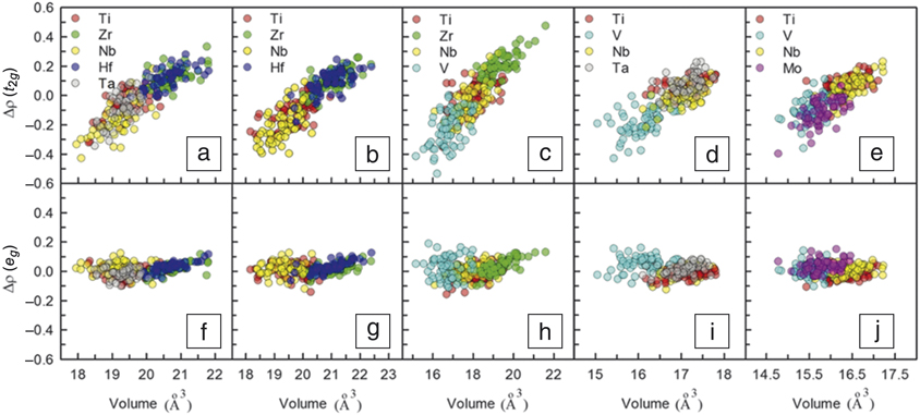
Local lattice distortions can be modeled well by ab initio density functional theory (DFT) calculations.Reference Tong, Zhao, Bei, Egami, Zhang and Zhang22 In particular, charge transfer from an element with a high Fermi level to one with a low Fermi level significantly affects the atomic size and the amount of local distortion. In the language of the tight-binding model, if the orbital levels of two elements are not equal (E A > E B) and bonding is asymmetric, the bonding orbital has a higher weight of the B element whereas the antibonding orbital has a higher weight of the A element. Thus, upon bond formation, the charge transfer from the antibonding orbital to the bonding orbital results in spatial charge transfer from A to B. For bcc alloys, charge transfer occurs mainly for the t 2g orbitals pointing to the nearest neighbor direction [111] and not for the e g orbital pointing to the second-nearest neighbor [100] direction (Figure 5).
The relation between charge transfer and Wigner–Seitz volume, a sphere whose volume is equal to the mean volume per atom in a solid. Correlations between atomic volumes and charge transfer of t 2g (upper panel) and e g (lower panel) orbitals for body-centered-cubic concentrated solid-solution alloys of TiZrNbHfTa (a, f), TiZrNbHf (b, g), TiZrNbV (c, h), TiVNbTa (d, i), and TiVNbMo (e, j).Reference Tong, Zhao, Bei, Egami, Zhang and Zhang22 Charge transfer occurs only for t 2g orbitals, but not for e g orbitals.

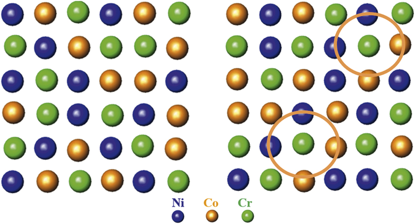
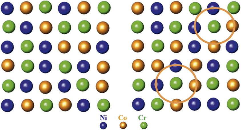
Although lattice distortion is less pronounced in fcc CSAs, a method has been developed to quantitatively determine the local lattice distortion with high accuracy through synchrotron x-ray/neutron techniques.Reference Zhang, Zhao, Jin, Xue, Velisa, Bei, Huang, Ko, Pagan, Neuefeind, Weber and Zhang21,Reference Tong, Jin, Bei, Ko, Pagan, Zhang and Zhang23–Reference Zhang, Tong, Jin, Bei, Weber, Huq, Lanzirott, Newville, Pagan, Ko and Zhang25 Short-range order was discovered experimentally in NiCoCr (Figure 6) in which the amplitude of vibration of Ni–Cr and Co–Cr bonds is significantly smaller than that of other pairs, suggesting Cr is favorably bonded with Ni and Co.Reference Zhang, Zhao, Jin, Xue, Velisa, Bei, Huang, Ko, Pagan, Neuefeind, Weber and Zhang21 The resultsReference Tong, Jin, Bei, Ko, Pagan, Zhang and Zhang23–Reference Zhang, Tong, Jin, Bei, Weber, Huq, Lanzirott, Newville, Pagan, Ko and Zhang25 also revealed that multiple elements could have a synergetic effect on local lattice distortion. Size mismatch cannot be regarded as a static effect, because local lattice distortion in NiCoCr, FeCoNiCr, and FeCoNiCrMn shows a relaxation phenomenon resulting from a surge of lattice expansion at low radiation doses, reaching a steady state at higher doses. On the other hand, local lattice distortion in FeCoNiCrPd monotonically increases with radiation dose. These studies suggest that a critical local lattice distortion may be required for stable and effective suppression of the growth of extended defects.
Schematic atomic arrangements: random structure of a multielement concentrated solid-solution alloy (CSA) (left). In a solid-solution NiCoCr alloy, short-range order is found, showing that Cr atoms favorably bond with Ni and Co atoms, as indicated by the two circles (right).
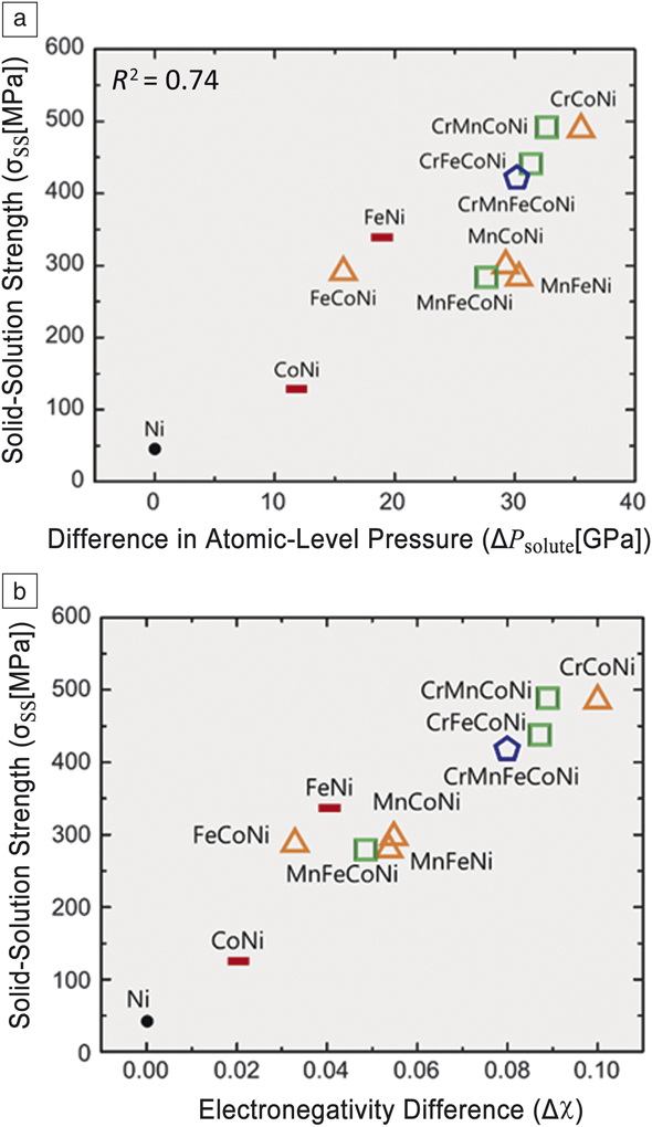
Atomic-level inhomogeneities: Chemical disorder-induced local lattice distortion strongly affects the properties of CSAs in multitudes of ways through the complex local potential energy landscape. For pinning dislocations, the local stress field plays a major role.Reference Labusch26–Reference Varvenne, Leyson, Ghazisaeidi and Curtin28 It was found that atomic-level stressReference Egami29 provides an excellent avenue to calculate the local stress field.Reference Oh, Kim, Odbadrakh, Ryu, Yoon, Mu, Körmann, Ikeda, Tasan, Raabe, Egami and Park30 As shown in Figure 7, the difference in the atomic-level pressure is closely related to the strength for many CSAs, evidencing that atomic-level pressure variation locally pins dislocations.
Solid-solution strength of concentrated solid-solution alloys (CSAs) is proportional to (a) the variation in atomic-level pressure and (b) electronegativity difference.Reference Oh, Kim, Odbadrakh, Ryu, Yoon, Mu, Körmann, Ikeda, Tasan, Raabe, Egami and Park30 Note: R 2, accuracy of linear fit.

The atomic-level pressure arises from a mismatch between the atom and the matrix in atomic size and electronic environment.Reference Egami29 Since CSAs are composed of 3d transition elements of similar sizes to allow a solid solution to form, the atomic-level pressure is dominated by the charge-transfer effect. The charge transfer is proportional to the difference in electronegativity for the elements (Figure 7b). This greatly simplifies the design strategy for CSAs.
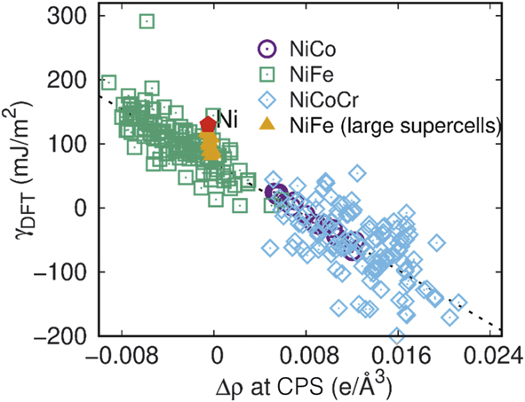
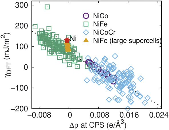
Effects of local atomic configurations on stacking faults: Stacking-fault energies (SFEs) in fcc CSAs govern structural stability, and local atomic configurations affect deformation mechanisms and vacancy clustering in CSAs composed of 3d transition elements.Reference Zhao, Osetsky, Stocks and Zhang31,Reference Zhang, Zhuang, Hu, Kai and Liu32 Ab initio electronic structure calculations show that the variation in SFEs is related to the charge redistribution at bond critical points (CPS, the points with zero gradient of charge density along the bond direction between neighboring atoms) in the stacking fault region (Figure 8).Reference Zhao, Osetsky, Stocks and Zhang31 A proposed model verified that local SFEs in NiCo can be accurately reproduced using local atomic concentrations as variables. Negative SFEs of NiCoCr and NiCoFeCr alloys were revealed by first-principles calculations and attributed to the thermodynamic metastability of fcc stacking sequence, which in turn affects the formation of stacking faults and nanotwins—underlying mechanisms behind the exceptional mechanical properties at cryogenic temperatures.Reference Zhang, Zhuang, Hu, Kai and Liu32
The dependence of calculated stacking fault energies from density functional theory, γDFT, on the charge density redistribution at bond critical points, Δρ at CPS, for NiCo, NiFe, and NiCoCr. The results calculated in pure Ni and larger supercells for NiFe (i.e., 3 × 5 rather than 2 × 3 in the x−y plane) are also indicated. The red pentagon denotes values in pure Ni.Reference Zhao, Osetsky, Stocks and Zhang31
Coupled electronic and atomic effects
The critical role played by energy transfer among electrons and atoms needs to be understood in order to properly model and predict defect production (see the section on “Defect evolution”) and the resulting structures (see the Microstructure progression section). Recent advances have enabled predictive capabilities to describe alloying effects in energy transport during radiation damage.
Nonadiabatic interactions of electrons with ions: Energy loss to target electrons (electronic stopping power, dE/dxe, where the e stands for electronic) is an important quantity used to predict and understand radiation effects in solids. From the early modelsReference Andersen and Sigmund33 of dE/dxe to the current first-principles simulations,Reference Ullah, Artacho and Correa34,Reference Tamm, Caro, Caro, Samolyuk, Klintenberg and Correa35 techniques have evolved to increase the range of validity and to reduce empiricism. The current theory and codes can account for almost all of the energy loss. Even for high projectile velocities, core electrons as deep as 2s 22p 6 are explicitly treated. With theoretical advances provided by time-dependent DFT and the development of numeric codes, simulation of the dE/dxe due to time-dependent participation of s- and d-band electrons becomes possible over a wide range of projectile velocities and for high-atomic-number projectiles.Reference Ullah, Artacho and Correa34 Electron–ion coupling with collective vibrational modes can also be modeled from first-principles simulations.
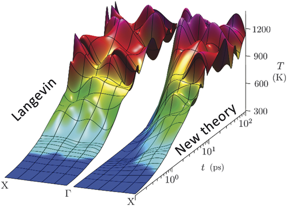
Recent work on electron–phonon molecular dynamics (EPH-MD)Reference Ullah, Artacho and Correa34,Reference Tamm, Caro, Caro, Samolyuk, Klintenberg and Correa35 reveals that the core electrons of a projectile open additional dissipation channels as the projectile velocity increases. EPH-MD is a software that simulates atomic evolution and thermodynamic properties of materials while accounting for electron–ion effects in a wide range of coupling strengths. The theory derived from first principles has the complexity required to realistically model the relaxation of an intricate system. This development in the field of statistical mechanics allows modeling of the fast (femtosecond) interactions of ions and electrons using quantum mechanics. Upon applying EPH-MD to Ni (Figure 9) and complex alloys, electrons excited above their ground states were found to be heated in various vibrational modes at different rates. This result contrasts with traditional Langevin dynamics, which equally damps all motion and therefore fails to sufficiently capture the influence of excited electrons.Reference Tamm, Caro, Caro, Samolyuk, Klintenberg and Correa35 The finding for nonadiabatic interactions of electrons with ions suggests that electron-mediated heating would couple to short-wavelength vibrations. Since short-wavelength modes do not propagate heat effectively, the localized heat allows a material to heal defects after irradiation events.
Simulated heating of atomic vibrations by fast laser using standard Langevin dynamics (left) and electron–phonon molecular dynamics (EPH-MD) (right). The EPH-MD results show differential heating—slow for long-wavelength mode (Γ) and fast for short-wavelength mode (X).

When energy transfer between ions and electrons in metals and alloys is accurately simulated, an atomistic view becomes available to explain the initial stages of defect formation and damage produced by energetic particles. Effects resulting from electronic excitations are hence incorporated seamlessly in MD models to correctly simulate the aftermath of ionizing radiation events, including electronic energy dissipation, phonon relaxation lifetimes, and temperature equilibration processes.Reference Tamm, Caro, Caro, Samolyuk, Klintenberg and Correa35 Simulations depict the thermalization of the highly nonequilibrium process with primarily first-principles data, suggesting that common empirical models might be erroneous in their estimation of the energy dissipated by electrons during collision cascades.
Effects of electron–phonon coupling on damage generation: Studies on SP-CSAs show closely coupled elastic and inelastic interactions under ion irradiation, in which the inelastic energy deposited to electrons significantly affects atomic processes, as the energy returned to the lattice via electron–phonon (e-ph) coupling enhances defect recombinationReference Zhang, Stocks, Jin, Lu, Bei, Sales, Wang, Béland, Stoller, Samolyuk, Caro, Caro and Weber9,Reference Granberg, Nordlund, Ullah, Jin, Lu, Bei, Wang, Djurabekova, Weber and Zhang14 and produces more isolated defects.Reference Zarkadoula, Samolyuk, Xue, Bei and Weber36–Reference Sellami, Debelle, Ullah, Christen, Keum, Bei, Xue, Weber and Zhang39
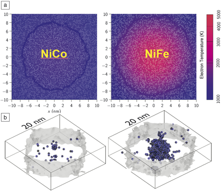
The electronic effects are shown to be more pronounced in higher-energy cascades, leading not only to less damage, but also to the formation of smaller defect clusters.Reference Zarkadoula, Samolyuk, Xue, Bei and Weber36 A pronounced effect is observed in more complex alloys because of their lower thermal conductivity and stronger e-ph coupling compared with single elemental Ni.Reference Zhang, Stocks, Jin, Lu, Bei, Sales, Wang, Béland, Stoller, Samolyuk, Caro, Caro and Weber9,Reference Jin, Sales, Stocks, Samolyuk, Daene, Weber, Zhang and Bei16–Reference Mu, Yin, Samolyuk, Wimmer, Pei, Eisenbach, Mankovsky, Ebert and Stocks18 For energy deposited from a swift heavy ion (>∼1 MeV/u, where nuclear energy deposition, dE/dxn, is negligible; the subscript n stands for nuclear),Reference Leino, Samolyuk, Sachan, Granberg, Weber, Bei, Lie, Zhai and Zhang37,Reference Sachan, Ullah, Chisholm, Liu, Zhai, Schauries, Kluth, Trautman, Bei, Weber and Zhang38 target electrons are initially excited as a result of extremely high dE/dxe along the ion path. Nonequilibrium defect formation is characterized in NiCoCr at different penetration depths along the paths of 1.542 GeV bismuth ions.Reference Sachan, Ullah, Chisholm, Liu, Zhai, Schauries, Kluth, Trautman, Bei, Weber and Zhang38 The formation of primary SFT is observed near the surface, where dE/dxe dominates. A mix of interstitial-type dislocation loops and vacancy-type SFT appears close to a deeper depth, near the maximum energy deposition from elastic interactions. Single-impact simulations performed using two-temperature MDReference Leino, Samolyuk, Sachan, Granberg, Weber, Bei, Lie, Zhai and Zhang37 suggest no melting or residual damage in pure Ni, whereas a cylindrical region is melted along the ion propagation path in NiFe and NiCo (Figure 10). The simulation results are supported by structural characterizations in bismuth-irradiated Ni and NiFe using scanning transmission electron microscopy annular bright-field imaging.Reference Leino, Samolyuk, Sachan, Granberg, Weber, Bei, Lie, Zhai and Zhang37
Residual damage in simulation cells. (a) Snapshot of molecular dynamic simulation cells 20 ps after the ion impact. The solid–melt interface is shown by the solid line, and electron temperatures are shown in color. (b) Melt–solid interface when molten radius is at its maximum. Small atom fragments are vacancies.Reference Leino, Samolyuk, Sachan, Granberg, Weber, Bei, Lie, Zhai and Zhang37

Atomic displacements under ion irradiation produce defects and defect clusters that induce lattice strain. Elastic strain and defect evolution are strongly correlated, and damage evolution under ionizing irradiation can be monitored via elastic strain developed in the irradiated crystals.Reference Sellami, Debelle, Ullah, Christen, Keum, Bei, Xue, Weber and Zhang39 To further understand coupled interactions, the effects of electronic energy deposition and dissipation on strain relaxation in irradiated CSAs were investigated.Reference Sellami, Debelle, Ullah, Christen, Keum, Bei, Xue, Weber and Zhang39 The results show that damage produced from displacement collision cascades is sensitive to subsequent highly ionizing irradiation, and that the strain generated by elastic nuclear collisions undergoes partial relaxation upon high-energy irradiation. This finding indicates a change in the damage structure upon electronic energy deposition, due to both predominant defect annealing and the growth of small defect clusters. Strain relaxation, more pronounced in CSAs than in Ni, is ascribed to both higher thermal conductivity and weaker e-ph coupling in Ni.
Defect evolution
The discovery of how energy carriers conducting energy links the grand challenge in materials research—to understand complex electronic correlations and nonequilibrium atomic interactions—with a quest to determine how such intrinsic properties and dynamic processes affect energy transfer and defect evolution in irradiated materials. The increasing chemical complexity, from pure Ni to complex CSAs, has been proven to significantly suppress damage accumulation at the early stages, which leads to distinct differences in microstructural evolution at later stages. The early stages of defect evolution and the late stages of microstructural evolution in SP-CSAs are reviewed next.
Interdiffusion under thermal equilibrium and sluggish diffusion under irradiation: Recent work shows that thermal-diffusion kinetics in CSAs depend not only on the number of alloying elements but also greatly on the elements present. The use of atomistic and mesoscale modeling techniques clears up the long-lasting confusion over the past two decades regarding the existence of sluggish diffusion, providing new insights into atomic transport in concentrated alloys.
Studies in composition-dependent thermal-diffusion kinetics and interdiffusionReference Jin, Zhang, Zhang and Bei40 show lower diffusion coefficients in CSAs with higher compositional complexity at homologous temperature. One exception: diffusion in NiCoFeCrPd is faster than in NiCoFeCr and NiCoCr, a result attributed to possible modification of the electronic structureReference Jin, Sales, Stocks, Samolyuk, Daene, Weber, Zhang and Bei16 and energy landscape (distorted translational symmetry that may modify the diffusion channels) due to the alloying 4d element palladium (Pd).
Sluggish diffusion is observed in CSAs when the diffusion coefficients are smaller than those of pure metals and conventional alloys. Modeling work based on μs-scale MD has identified the existence of a minimal compositional dependence of the tracer diffusion coefficient in Ni-Fe binary CSAs.Reference Osetskiy, Beland, Barashev and Zhang13 Mesoscale modeling using the kinetic activation relaxation technique with on-the-fly approach has confirmed that the phenomenon exists because of structural and energetic features of defect migration in concentrated alloys. Composition-dependent vacancy jump barriers resulting from different alloying elements have been identified using conventional lattice kinetic Monte Carlo (kMC) simulations. The maximum sluggish effect occurs with the maximum difference in activation energy for vacancy migration via different atoms. More importantly, the origin of sluggish diffusion in Ni-Fe alloys is delineated, showing percolation of vacancy diffusion via the Fe subsystem and a strong dependence of the vacancy migration energy in Ni-Fe alloys on both overall alloy composition and local chemical environments. The gradual increase in sluggishness of interstitialReference Osetskiy, Beland, Barashev and Zhang13 and vacancyReference Barashev, Osetsky, Bei, Lu, Wang and Zhang41 migration with increasing Fe concentration enhances interstitial and vacancy recombination. A transition from long-range one-dimensional (1D) defect motion to short-range 3D motion has been identified as the predominant migration mechanism for interstitial clusters in the binary alloys, contrary to the 1D mode that dominates in pure Ni and some well-studied dilute alloys.Reference Barashev, Osetsky, Bei, Lu, Wang and Zhang41 An efficient approach has been demonstrated for preselecting candidate CSAs with desirable atomic transport properties using conventional kMC modeling with parameters obtained from first-principles electronic density calculations.Reference Osetskiy, Beland, Barashev and Zhang13
Validation of interatomic potentials: It is known that the bottleneck in an atomistic simulation approach is the availability of a reliable interatomic potential for describing the ion and target interactions. It is, however, even more challenging to simulate radiation effects in CSAs under nonequilibrium conditions than to model fundamental materials properties under an equilibrium condition.
New developments in cascade simulationsReference Béland, Osetsky and Stoller42,Reference Stoller, Tamm, Béland, Samolyuk, Stocks, Caro, Slipchenko, Osetsky, Aabloo, Klintenberg and Wang43 reveal the existence of extreme pressures and temperatures arising from high-energy recoils. These recoils, with energies of tens of keV, generate a supersonic shockwave.Reference Béland, Osetsky and Stoller42 Analysis shows that pressures of the order of 10–50 GPa and temperatures of several thousand K are present as the shock wave transitions to a sonic velocity. Further analysis shows that the number of atomic displacements during the supersonic-to-sonic transition is a good predictor of the number of surviving defects. The extreme pressures involved are associated with interatomic distances ranging between 0.14 and 0.2 nm, where most force fields commonly used for atomistic modeling are poorly parameterized. In other words, the analysis of high-energy displacement cascadesReference Béland, Osetsky and Stoller42 has revealed that neutron- and ion-irradiated materials are subject to extreme pressures involving tens of GPa and short interatomic distances, which are typically inaccurately modeled. Applying different smooth curve fits to join the ZBL potential (Ziegler–Biersack–Littmark potential, describing close atomic interaction) with the potentials in an equilibrium environment may result in artificially higher or lower defect production. This is a serious pitfall for quantitative comparison of primary defect production in different material systems (e.g., Ni, Fe, alloys, and HEAs).
Researchers have tested and benchmarked several ab initio-based methods to calculate short-range interactions of atoms, including those in high-pressure states.Reference Stoller, Tamm, Béland, Samolyuk, Stocks, Caro, Slipchenko, Osetsky, Aabloo, Klintenberg and Wang43 Using the ab initio-based information, they have introduced a novel framework to refit classical interatomic force fields and have shown the robustness of their new approach, relative to the ad hoc procedure typically used by the community.Reference Stoller, Tamm, Béland, Samolyuk, Stocks, Caro, Slipchenko, Osetsky, Aabloo, Klintenberg and Wang43 Their resultsReference Béland, Osetsky and Stoller42,Reference Stoller, Tamm, Béland, Samolyuk, Stocks, Caro, Slipchenko, Osetsky, Aabloo, Klintenberg and Wang43 have raised doubts regarding the accuracy of many previous results reported in the literature. Nevertheless, the development of force fields with high dependability at these short interatomic distances is a challenging topic to be addressed that involves a huge number of ab initio calculations and validations.
Defect annihilation: Just as dislocations are pinned by defects in conventional alloys, defects in SP-CSAs are also pinned by chemical disorder. However, the pinning strength depends on the nature of the defects and chemical environment.
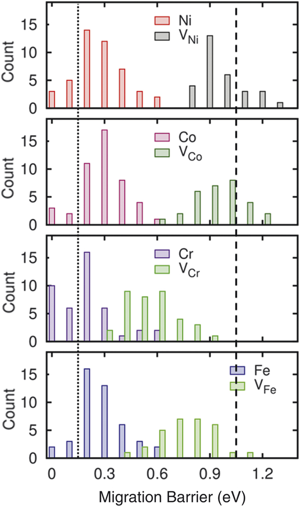
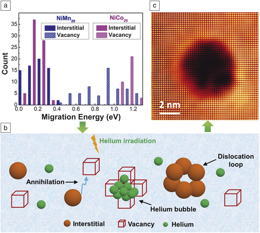
Defect energies in equiatomic NiCoCr and NiCoFeCr exhibit a large overlap in the distribution of migration energies for Cr/Fe interstitials and vacancies (Figure 11).Reference Zhao, Egami, Stocks and Zhang12,Reference Zhao, Stocks and Zhang44 Overlap in the migration energies indicates that both interstitials and vacancies defects are mobile at the same temperature, which might lead to enhanced interactions between interstitials and vacancies, and therefore increased defect recombination. It has also been found that interstitial defects, which suffer from strong repulsion by the matrix, relax much more significantly with chemical disorder than do vacancies. Consequently, the migration barrier for an interstitial defect is twice as large in CSAs than in a pure metal, whereas the barrier for a vacancy is smaller. The distribution of the migration barrier heights in NiCoFeCr is calculated by DFT simulation (Figure 11).Reference Zhao, Egami, Stocks and Zhang12 The barrier height for interstitial defects in pure Ni is only 0.15 eV (dotted line), and that for vacancies in pure Ni is 1.04 eV (dashed line). The results in Figure 11 clearly show that the barrier heights for interstitial defects are appreciably higher in CSAs.
Distribution of migration barrier heights in NiCoFeCr, for interstitials (e.g., Ni and Co) and vacancies (e.g., VNi and VCo).Reference Zhao, Egami, Stocks and Zhang12 The vertical axis shows the counts in modeling, proportional to probability. The lines indicate the barrier heights in pure Ni.

Modified defect energetics for different elements in CSAsReference Zhao, Egami, Stocks and Zhang12 have a significant impact on irradiation resistance. Irradiation of particles on a solid creates a large number of Frenkel defects (vacancy-interstitial pairs). In pure elements, interstitial defects are so mobile that they quickly sink to grain boundaries or surfaces, leaving vacancies behind that coagulate as voids, resulting in swelling. However, chemical disorder leads to sluggish diffusion and stabilizes interstitial defects in CSAs, so that most of the Frenkel pairs recombine and are annealed, therefore suppressing void swelling—one of the reasons why CSAs are promising as nuclear materials.
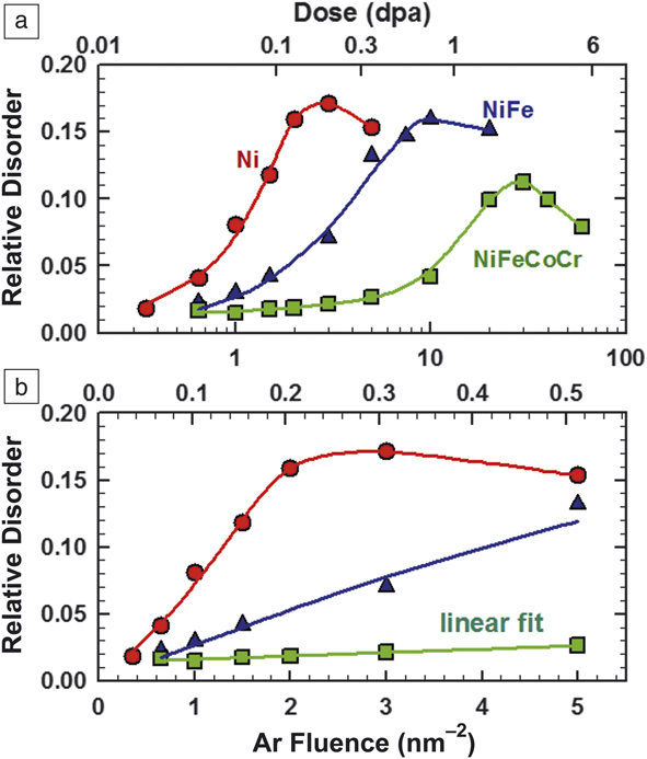
Defect accumulation: Advances in making high-quality single crystals make it possible to experimentally investigate early-stage defect evolution, including defect production and damage accumulation with increasing chemical complexity.Reference Lu, Niu, Chen, Jin, Yang, Xiu, Zhang, Gao, Bei, Shi, He, Robertson, Weber and Wang15,Reference Velişa, Wendler, Zhao, Jin, Bei, Weber and Zhang45,Reference Shi, He, Jin, Bei and Robertson48 Rutherford backscattering spectrometry (RBS) along a channeling direction has been used to probe radiation damage in irradiated materials.Reference Zhang, Stocks, Jin, Lu, Bei, Sales, Wang, Béland, Stoller, Samolyuk, Caro, Caro and Weber9,Reference Zhang, Zhao, Weber, Nordlund, Granberg and Djurabekova10,Reference Granberg, Nordlund, Ullah, Jin, Lu, Bei, Wang, Djurabekova, Weber and Zhang14,Reference Velişa, Wendler, Zhao, Jin, Bei, Weber and Zhang45 Irradiation-induced damage (e.g., the formation of defects and dislocation loops) can be reflected by increased RBS yields. The evaluation of irradiated SP-CSAsReference Velişa, Wendler, Zhao, Jin, Bei, Weber and Zhang45 clearly exhibits suppressed damage accumulation in NiFeCoCr at 16 K with a linear dependence as a function of ion fluence, in sharp contrast to Ni and NiFe (Figure 12). This effect—which is not thermally activated—is attributed to the large difference in electronic scattering and magnetic frustration at this low temperature,Reference Zhang, Stocks, Jin, Lu, Bei, Sales, Wang, Béland, Stoller, Samolyuk, Caro, Caro and Weber9,Reference Mu, Samolyuk, Wimmer, Troparevsky, Khan, Mankovsky, Ebert and Stocks17,Reference Mu, Yin, Samolyuk, Wimmer, Pei, Eisenbach, Mankovsky, Ebert and Stocks18 as well as the complex defect energy landscapeReference Zhang, Zhao, Weber, Nordlund, Granberg and Djurabekova10,Reference Zhao, Egami, Stocks and Zhang12,Reference Osetskiy, Beland, Barashev and Zhang13 in these alloys that limits defect mobility (e.g., unstable interstitial positions and high-energy migration barriers) and enhances defect interaction and recombination. The remarkably slow defect evolution and therefore delayed damage accumulation is attributed to the intrinsic “self-healing” property of chemically complex SP-CSAs.
Disorder at damage peak as a function of both Ar-ion fluence (bottom axis) and local dose (top axis) in displacements per atom (dpa) for Ni, NiFe, and NiFeCoCr irradiated with 500 keV Ar ions at 16 K. For better visibility of data, (a) logarithmic and (b) linear scales are used.Reference Velişa, Wendler, Zhao, Jin, Bei, Weber and Zhang45

Synergetic investigation with experimental, computational, and modeling approaches reveals the suppression of defect accumulation and retarded dislocation evolution in Ni-Fe alloys with increasing Fe concentrationReference Lu, Yang, Niu, Peng, Jin, Crespillo, Velisa, Xue, Zhang, Xiu, Zhang, Gao, Bei, Weber and Wang46 and in Ni0.8X0.2 (X = Fe, Cr, Mn, and Pd) CSAs.Reference Yang, Lu, Velisa, Jin, Xiu, Crespillo, Zhang, Bei and Wang47 Quantitative analysis of the impact of chemical complexity is further achieved by direct observation in a transmission electron microscope (TEM), where the evolution of defects is observed in metal Ni and a series of SP-CSAs, from binaries to HEAs, under 1 MeV Kr ion irradiation at 773 K.Reference Shi, He, Jin, Bei and Robertson48 The defect evolution in different CSAs with various level of chemical complexity is assessed through measurements of the defect density, defect size, and fraction of perfect and Frank loops. The faulted Frank loops are observed to “unfault” into perfect loops with increasing ion doses. The formation and population of loops are sensitive to the ion dose and alloy composition, and the dependence is examined in terms of the influence of each alloying element on defect formation and migration energies.
Microstructure progression
Increasing compositional complexity in SP-CSAs has been shown to significantly suppress void swelling, by two orders of magnitude, at elevated temperatures.Reference Lu, Niu, Chen, Jin, Yang, Xiu, Zhang, Gao, Bei, Shi, He, Robertson, Weber and Wang15, Reference Yang, Lu, Velisa, Jin, Xiu, Crespillo, Zhang, Bei and Wang47–Reference Yang, Lu, Velisa, Jin, Xiu, Zhang, Bei and Wang49 Pd-HEAs have shown stronger suppression of void growth at higher temperatures than Mn-HEAs. Nonetheless, void swelling occurs in Pd-HEAs with high-density preexisting dislocations.Reference Lu, Yang, Jin, Velisa, Xiu, Song, Peng, Gao, Zhang, Bei, Weber and Wang50 Recent work on CSAs provides clear evidence of chemical effects on He behavior in CSAs and evidence that strategies of tailoring chemical complexity can alter vacancy and interstitial migration energies, thereby suppressing He bubble formation and growth during irradiation. In other words, tailoring defect cluster motion in alloys provides a new guideline for designing radiation-tolerant materials for use at elevated temperatures.
Effects of alloying elements and swelling resistance: Studies of the effects of alloying elements on radiation-induced microstructural evolution in Ni and binary alloysReference Yang, Lu, Velisa, Jin, Xiu, Crespillo, Zhang, Bei and Wang47 reveal that the average size of defect clusters decreases as the atomic volume size factor of the alloying element increases, and oversized atoms act as strong trapping sites for interstitials. Smaller void size in the near-surface region in Ni0.8Cr0.2 has been attributed to faster vacancy mobility. The smaller voids observed in Ni0.8Mn0.2 and Ni0.8Pd0.2 beyond the damage peak are due to the stronger Mn/Pd-vacancy binding effect of greatly oversized alloying atoms. The larger the atomic volume factor, the stronger the trapping force, leading to a more significantly sluggish interstitial migration and smaller dislocation loop size. The average dislocation loop size in Ni0.8Fe0.2 is 4× larger than in Ni0.8Pd0.2 (atomic volume factor of 10.6% and 41.3%), but an order of magnitude lower in density. The smaller dislocation loop size in Ni0.8Cr0.2 is attributed to stronger interstitial binding of Cr-Ni.
Combined experimental, theoretical, and modeling studies reveal and delineate controlling mechanisms of high swelling resistance observed in ion-irradiated Ni-Fe equiatomic alloys.Reference Barashev, Osetsky, Bei, Lu, Wang and Zhang41 The element-specific and composition-dependent features of atomic mass transport identified in CSAs show that chemically biased diffusion via vacancies and interstitials creates segregations near defect sinks that lead to increasing segregation bias, which prevents void growth and converts void nuclei into Ni-rich precipitates. Complete suppression of the 1D glide of interstitial clusters/dislocation loops prevents production bias, increases sink strength, enhances the flow of Ni atoms toward interstitial components, and creates Fe-rich channels for vacancy migration out of the damage region.
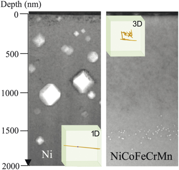
Significant suppression of irradiation-induced void swelling by tailoring of defect migration mode: Suppression of void formation by two orders of magnitude at elevated temperature has been achieved by increasing the compositional complexity in Ni-containing equiatomic SP-CSAs.Reference Lu, Niu, Chen, Jin, Yang, Xiu, Zhang, Gao, Bei, Shi, He, Robertson, Weber and Wang15 Enhanced swelling resistance was attributed to the tailored interstitial defect cluster motion in the alloys, from 1D mode to 3D mode (Figure 13).Reference Lu, Niu, Chen, Jin, Yang, Xiu, Zhang, Gao, Bei, Shi, He, Robertson, Weber and Wang15 Cross-sectional TEM images of pure Ni and Ni-containing SP-CSAs irradiated by Ni ions at 773 K show that the resulting microstructure can be qualitatively differentiated into two distinct groups. Nickel and NiCo show large voids in the irradiated region, in front of the interstitial-type dislocation structures. More complex alloys show interstitial-type dislocation loops in the irradiated region, followed by much smaller voids distributed beyond the end of the ion range. The unique defect cluster distributions are attributed to different migration behaviors of interstitial clusters in these materials.Reference Barashev, Osetsky, Bei, Lu, Wang and Zhang41 Simulations reveal that interstitial clusters migrate in 1D motion in pure Ni and NiCo, but in 3D motion in NiFe.Reference Lu, Niu, Chen, Jin, Yang, Xiu, Zhang, Gao, Bei, Shi, He, Robertson, Weber and Wang15 The transition from long-range 1D to short-range 3D migration modes of interstitial defect clusters is found to considerably increase the vacancy–interstitial recombination rate, greatly reduce the damage accumulation, and lead to insignificant void swelling in CSAs under ion irradiation.
Cross-sectional transmission electron microscope image showing void distributions in Ni and NiCoFeCrMn irradiated with 3 MeV Ni ions to 5 × 1016 cm–2 at 773 K. The significant swelling resistance in NiCoFeCrMn is attributed to the 3D migration mode of the interstitial clusters.

Studies of temperature-dependent void swelling and dislocation loop evolution in equiatomic NiCoFeCrMn and NiCoFeCrPd (i.e., Mn-HEA and Pd-HEA) have shown no phase decomposition in either alloy. An order of magnitude higher swelling was seen in both HEAs as temperature increased from 420°C to 580°C.Reference Yang, Lu, Velisa, Jin, Xiu, Zhang, Bei and Wang49 Alloying with Pd was found to have a stronger suppression effect on void and dislocation loop growth than alloying with Mn. Possible contributions to the swelling resistance include localized lattice distortion and a higher defect migration barrier in Pd-HEA. Study of the role of dislocations in ion irradiation–induced void formation in Pd-HEAs reveals that swelling is enhanced with an increasing density of preexisting dislocations at low strain levels that shorten the transient duration before the onset of void swelling.Reference Lu, Yang, Jin, Velisa, Xiu, Song, Peng, Gao, Zhang, Bei, Weber and Wang50 Compared with Mn-HEA, Pd-HEA has a smaller loop size and higher loop density due to the stronger lattice distortion.
Suppressing He bubble growth: It has been demonstrated that vacancy and interstitial migration energies can be tailored through careful selection of alloying elements and composition to suppress the growth of detrimental He bubbles in Ni-based CSAs subjected to irradiation (Figure 14).Reference Fan, Zhao, Jin, Chen, Osetskiy, Wang, Bei, More and Zhang51,Reference Wang, Jin, Chen, Bei, Wang, Weber, Zhang and More52 The aggregation of vacancies and He atoms leads to the formation and growth of He bubbles, which degrade alloy properties under irradiation. A narrower gap between the migration energies of interstitials and vacancies promotes interstitial-vacancy recombination and leaves fewer available vacancies to contribute to He bubble growth. Combined TEM observations and DFT calculations for five Ni-based alloys (Ni0.8X0.2 X = Co, Fe, Cr, Pd, Mn) find that Ni0.8Mn0.8 has the smallest difference in vacancy–interstitial migration energies and the least radiation damage accumulation (e.g., the smallest bubbles). In addition, increasing the Fe concentration in Ni(1–x)Fex causes more He to be trapped within smaller bubbles. The strategy of tuning defect migration energies via the selection of alloying elements and varying their concentrations can be applied to design structural alloys with improved radiation tolerance.
Closer migration energies of interstitials and vacancies (a) promote annihilation of vacancies (b), which leads to suppressed growth of helium bubbles (c).

Discussion
Means of improving the performance of structural materials have been intensively investigated for many decades. Solid-solution strengthening, traditionally by alloying minor elements into pure metals, is one of the most widely used methods to achieve specific desirable properties. While it has long been recognized that specific compositions in binary and some ternary alloys have better radiation resistance than their pure metal counterparts, it remains unclear how the alloy effects at the level of electrons and atoms affect defect properties and defect dynamics. The knowledge gap has been a roadblock to future-generation energy technologies.
In SP-CSAs, the global lattice structure is periodic, but chemical periodicity is lost because of chemical disorder. Each atom has a different chemical environment. To maintain a single phase, the elements involved are expected to have similar atomic sizes and chemical characters. Naturally, SP-CSAs are frequently formed by transition metals, and the multicomponent alloys of 3d and 4d elements have been widely studied. In particular, because the atomic sizes of these alloying elements are similar, electronic effects play major roles in forming structures, and the use of ab initio calculations is a requisite. Electrons redistribute (charge transfer) and atoms are locally displaced to accommodate the chemical variation. The results reviewed here demonstrate that the effects of chemical complexity are not additive but are profoundly emergent. For charge transfer,Reference Egami, Ojha, Khorgolkhuu, Nicholson and Stocks53 the amount of transfer is not large, typically a few tenths of electrons. However, because the Coulomb force is so strong, this can create dramatic effects and profoundly influence the alloy properties.
Because of global lattice periodicity, lattice defects are topologically protected, but their potential energy landscape (PEL) is highly disordered as a result of chemical disorder. Defects tend to be trapped in local minima of the PEL, and their mobility is reduced. This reduction in defect mobility is, in many cases, advantageous for nuclear applications, as has been suggested by the early demonstration of the high tolerance of SP-CSAs against electron damageReference Nagase, Anada, Rack, Noh, Yasuda, Mori and Egami54,Reference Nagase, Rack, Noh and Egami55 and, more recently, against ion irradiation.Reference Zhang, Stocks, Jin, Lu, Bei, Sales, Wang, Béland, Stoller, Samolyuk, Caro, Caro and Weber9,Reference Zhang, Zhao, Weber, Nordlund, Granberg and Djurabekova10,Reference Lu, Niu, Chen, Jin, Yang, Xiu, Zhang, Gao, Bei, Shi, He, Robertson, Weber and Wang15 For instance, the reduction in mobility of interstitial defects enhances the probability of recombination of Frenkel pairs produced by irradiation, resulting in reduced swelling. Dislocations are locally pinned, increasing mechanical strength.Reference Oh, Kim, Odbadrakh, Ryu, Yoon, Mu, Körmann, Ikeda, Tasan, Raabe, Egami and Park30 To maximize such benefits, it is important to understand the effects of chemical complexity on the local structure. Whereas the effect of a single impurity (solute) in the matrix (solvent) has long been investigated, the nature of massive chemical complexity in SP-CSAs is not well understood.
Alloy design for nuclear and other applications should take the electronic, atomic, and coupled effects fully into account. Because of their chemical complexity, SP-CSAs offer wide ranges of variation in electronic and structural properties and allow many knobs that can be turned in designing materials for the desired functionality.
Summary
The continuous discovery of unexpected properties of SP-CSAs has drawn immense attention and opened new frontiers in materials research. Going beyond simple qualitative compositional manipulation, research in SP-CSAs has clearly shown that extreme chemical complexity, as a result of compositional/elemental disorder, is conceptually different from dilute solutes or nanoscale features. As reviewed here, that chemical disorder in SP-CSAs—with different numbers of principal elements or altered concentrations of specific elements—can be manipulated to produce distinct electronic structures and atomic arrangements, for the purpose of improving radiation resistance.
The extreme chemical disorder of SP-CSAs can reduce electron, phonon, and magnon mean free paths. It is thus possible to modify the strengths of coupled ballistic recoil and electronic processes, control energy dissipation pathways and rates, alter the defect energetics, and ultimately affect both the early stages of radiation damage (when defects are created following the transfer, equilibration, and dissipation of simultaneous elastic and inelastic energy deposition) and the late stages of microstructural evolution (when damage accumulates). Current research has shown that a local environment with distinctive electronic- and atomic-level properties can control kinetic energy, heat, and mass transport. Modifying energy landscapes and tailoring atomic transport processes by tuning the chemical complexity of SP-CSAs can effectively impact both defect production during collisional energy transfer in the femtosecond to picosecond time frame and damage evolution over much longer time scales. The slow energy dissipation affects defect dynamics at the early stages and consequentially may result in less deleterious defects.
The development and study of unique SP-CSAs prompts fundamentally new questions that challenge established theories and models currently applicable to conventional alloys; it may also hold the promise for revolutionary advances in understanding equilibrium and nonequilibrium transport processes in multiphase structurally complex alloys, and provide a foundation to enable breakthroughs in the design of revolutionary new materials with exotic functionality and incredible strength and stability. The studies reviewed here show that the intrinsic chemical complexity of SP-CSAs manifests and ultimately controls the dissipation of radiation energy under extreme conditions. More fundamentally, they represent a major scientific challenge: can we take advantage of property enhancements resulting from alloying and chemical disorder to go beyond linear extrapolation to yield new design principles for radiation-tolerant structural alloys aimed at applications in the nuclear energy field, as well as a broad range of energy technologies?
Acknowledgments
This work was supported as part of the Energy Dissipation to Defect Evolution, an Energy Frontier Research Center funded by the US Department of Energy (DOE), Office of Science, Basic Energy Sciences under Contract No. DE-AC05–000R22725. Some electron microscopy analyses were performed as part of a user proposal at Oak Ridge National Laboratory’s Center for Nanophase Materials Sciences, which is a DOE Office of Science User Facility. Heavy ion irradiations and ion-beam analysis were performed at the Ion Beam Materials Laboratory (ibml.utk.edu) located on the campus of The University of Tennessee, Knoxville.

Yanwen Zhang is a distinguished R&D staff member at Oak Ridge National Laboratory and a joint faculty member with The University of Tennessee, Knoxville. She received her BS degree in 1990 and her MS degree in 1993 in solid-state physics at Beijing Normal University (BNU), China, her PhD degree in nuclear physics in 1998 from Lund University, Sweden, and her PhD degree in science in 1999 from BNU. She conducted research at Uppsala University, Sweden, from 1999 to 2001, and at Pacific Northwest National Laboratory from 2002 to 2010. Her research focuses on the interactions of ions, electrons, and photons with materials and how these interactions can be applied to modify, characterize, and control materials. Zhang can be reached by email at Zhangy1@ornl.gov.

Takeshi Egami is a University of Tennessee–Oak Ridge National Laboratory distinguished scientist and professor. He received his BS degree in 1968 in applied physics from The University of Tokyo, Japan, and his PhD degree in 1971 in materials science from the University of Pennsylvania. Prior to his current position, he was a professor at the University of Pennsylvania from 1973 to 2003. His research specialty is highly disordered materials, including liquids, glasses, and disordered crystalline metals and oxides, explored using neutron and x-ray scattering, simulation, and theory. Egami can be reached by email at egami@utk.edu.

William J. Weber is a Governor’s Chair professor in materials science and engineering at The University of Tennessee, Knoxville. He received his BS degree in 1971 in physics from the University of Wisconsin–Oshkosh, his MS degree in 1972, and his PhD degree in 1977 in nuclear engineering from the University of Wisconsin–Madison. He conducted research at Pacific Northwest National Laboratory from 1977 to 2010. His research focuses on radiation effects in materials, ion-beam modification of materials, and defects in ceramics. Weber can be reached by email at wjweber@utk.edu.