I. INTRODUCTION
With the development of high power density of electronic and microelectronic devices, many application fields including electronic packaging, aerospace, and space exploration have placed a greater demand on the properties of materials. In recent years, aluminum matrix composites with excellent comprehensive properties have attracted increasing attention of researchers since a proper control of the ratio of reinforcement added to aluminum matrix offers excellent tailorability of thermal and mechanical properties.Reference Qu, Zhang, Wu and Ren1–Reference Son, Kim, Park, Cho and Cho3 Until now, several promising carbon-based materials (e.g., ceramic particles, carbon fibers, carbon nanotubes, diamond particles, graphite flakes, graphite foam, etc.) have been widely investigated and integrated in aluminum alloy matrix via various fabrication techniques.Reference Tan, Li, Fan, Guo, Kai, Ji, Zhang and Zhang4–Reference Lalet, Kurita, Miyazaki, Kawasaki and Silvain9 Actually, SiC/Al composites are limited in the field of thermal management owing to its low thermal conductivity (TC). Diamond/Al composites have high price and poor machinability, despite its excellent thermal properties with TC approaching 600 W/m K, which makes the postprocessing of the materials impossible and limits the industrial applications.Reference Tan, Li, Fan, Guo, Kai, Ji, Zhang and Zhang4–Reference Zhang, Wu, Zhang, Li and Wang6 Carbon nanotubes/Al composites have very high TC, but the dispersion and orientation of carbon nanotubes in the aluminum alloy matrix have been a difficult problem for researchers.Reference Khorasani, Heshmati-Manesh and Abdizadeh7 Carbon fiber/aluminum matrix composites with high TC have demonstrated a great potential in application, but the difficulty of preparation process and the high price make it unable to meet the need of industrial production.Reference Kurita, Feuillet, Guillemet, Heintz, Kawasaki and Silvain8,Reference Lalet, Kurita, Miyazaki, Kawasaki and Silvain9
Recently, highly oriented graphite flakes have become a promising reinforcement for thermal management composites owing to its high TC approaching 1000 W/m K, negative coefficient of thermal expansion (CTE) to −1.0 × 10⁻⁶/K in the a–b plane, low density, and ease to machinability.Reference Kurita, Miyazaki, Kawasaki, Lu and Silvain10,Reference Murakami, Nishiki, Nakamura, Ehara, Okada, Kouzaki, Watanabe, Hoshi and Yoshimura11 Therefore, the graphite flakes reinforced aluminum matrix composites (Gf/Al), if processed properly, can offer a well combination of high TC, low CTE, and superior machinability, which makes it very attractive to meet the ever-increasing market demand. However, in the conventional Gf/Al composites, stacking of graphite flakes leaves almost no space between the graphite layer, which makes the infiltration of molten aluminum an almost unfeasible task. In such context, increasing researches are addressed on the hybrid aluminum matrix composites reinforced with graphite flakes and other particles. SiCReference Prieto, Molina, Narciso and Louis12 and SiReference Zhou, Ji, Chen, Wang, Addad, Schryvers and Wang13 particles were doped to the graphite/aluminum matrix composites, respectively, which all acted as space between the layers of Gf, and the TCs are up to 390 W/m K and 526 W/m K respectively. Furthermore, TiO2,Reference Son, Kim, Park, Cho and Cho3 B4C,Reference Thirumalai, Subramanian, Kumaran, Dharmalingam and Ramakrishnan14 Al2O3, (Ref. Reference Basavarajappa, Chandramohan and Davim15) and other particles can form a multiphase hybrid system with Gf to improve the TC of composites.
In this study, hybrid aluminum matrix composites reinforced with Si and graphite flakes were fabricated by vacuum gas pressure infiltration. Microstructure was characterized by x-ray diffraction (XRD), x-ray photoelectron spectroscopy (XPS), optical microscopy (OM), and field emission scanning electron microscopy (FE-SEM) to investigate the presence of Al4C3 in particular and more generally the detailed graphite/Al interface assembly configuration. The effect of the volume fractions of graphite on TC of the composites was also investigated and discussed. Besides, we established corresponding predictive models for the TC of the composites by considering the observed microstructural features.
II. MATERIALS AND METHODS
A. Materials
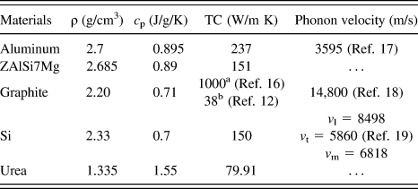
The raw materials used in this work mainly consisted of graphite flakes, Si particles, and Al alloy. Graphite flakes (Gf) are platelets of 500 µm of average diameter and thickness of around 25 µm [see Fig. 1(a)], purchased from Shandong Graphite Corporation. The average diameter of Si particles is about 75 µm [see Fig. 1(b)], purchased from Sinopharm Chemical Reagent Co., Ltd. ZAlSi7Mg is chosen for infiltration instead of pure Al due to its good fluidity and lower melting temperature preventing the formation of Al4C3. The pore-forming agent is urea, purchased from TianLi Corporation. The thermo-physical properties of raw materials are given in Table I.
Micrographs of the reinforcements used in this work: (a) graphite flakes, (b) Si particles, (c) the photo of mould for preparing the preform and cutting samples of Gf/Si/Al composites. Schematic of the fabrication process: (d) the process of Gf preform and (e) vacuum pressure infiltration.

The thermo-physical properties of several raw materials.
a Parallel to the graphite layers.
b Perpendicular to the graphite layers.
B. Fabrication of the Gf/Si/Al composites
Figure 1(d) illustrates the typical fabrication process of the Gf preform. This process consists of three steps: (i) mixing of graphite flakes, urea, and Si particles by the ratio in the range of 8:8:1–56:8:1, (ii) the mixture was then loaded in a mold [see Fig. 1(c)] and pressed to obtain a block by a mechanical pressure of 25 MPa, (iii) the obtained blocks were sintered at 400 °C for 2 h under the argon atmosphere and achieved a formation of porous graphite preform. The vacuum gas pressure infiltration process is shown in Fig. 1(e), Al alloy was heated to molten state and pressed into infiltration chamber. Then, under a vacuum of 2 MPa the porous preform was infiltrated by molten aluminum alloy at 720 °C for 5 s. This process can prevent the formation of Al4C3 effectively due to a low infiltration temperature and a short contact time. Finally, the composites were cut into 2.5 mm × 4.2 mm × 12.7 mm of the sample [see Fig. 1(c)] by the wire–electrode cutting process to test the TC and other properties.
C. Phase analysis and microstructural characterization
The microstructure of the Gf/Si/Al composites on the fractured surface was analyzed by FE-SEM Quanta 600 FEG (America FEI, Hillsboro, Oregon). equipped with an energy disperse spectroscopy (EDS) system. The presence of Al4C3 in the interface between graphite and aluminum was checked by XRD (PANalytical, Holland, Netherlands) and XPS ESCALAB 250 (Thermo Fisher Scientific, Shanghai, China). Distribution of phases in composites was analyzed by OM Olympus MPG4 (OCN, Shanghai, China) and the volume fraction of graphite (v f) was determined by the image analysis software based on a gray-scale threshold criterion. Once the volume fraction of graphite was measured, the determination of the volume fractions of both Al alloy and Si particles (v mp = v m + v p) was known. We assumed that x p is the volume fractions of Si particles in the binary ZAlSi7Mg–Sip composites and it can be calculated by Eq. (1):
 $$x_{{\rm{Si}}} = {{v_{\rm{p}} } \over {v_{\rm{m}} + v_{\rm{p}} }}\quad ,$$
where v p is the volume fraction of Si in Gf/Si/Al composites, and it can be estimated by Eq. (2):
 $$v_{{\rm{Si}}} = {{{{m_{{\rm{Si}}} } \mathord{\left/ {\vphantom {{m_{{\rm{Si}}} } {\rho _{{\rm{Si}}} }}} \right. \kern-\nulldelimiterspace} {\rho _{{\rm{Si}}} }}} \over {V_{\rm{c}} }}\quad .$$
Here, it should be explained that V c is the volume of obtained composites measured by a method of draining water.
D. Measurements of TC
The TC (λ) of the Gf/Si/Al composites was calculated from the thermal diffusivity (α), density (ρ), and specific heat capacity (c p) using Eq. (3)Reference Yuan, Li, Dong, Westwood, Cui, Cong, Du and Kang18:
 $$\lambda = \alpha \times c_{\rm{p}} \times \rho \quad {\rm{.}}$$
The thermal diffusivity of Gf/Si/Al composites (parallel to the graphite layers) was measured by the laser-flash diffusivity instrument, Nano-Flash-Apparatus, LFA 447 (NETZSCH, Saarbrücken, Germany). Nano-Flash-Apparatus, LFA 447, NETZSCH). The density and porosity of Gf/Si/Al composites were measured by electron density meter DE-120M (DahoMeter, Shenzheng, China). The specific heat capacity of the composites was calculated by the linear rule of mixtures using the specific heat capacity values of the components (i.e., Gf, Si particles, and Al alloy).Reference Prieto, Molina, Narciso and Louis12
III. RESULTS AND DISCUSSIONS
A. Microstructure observation
FE-SEM micrographs reveal that graphite flakes are closely attached and oriented perpendicular to the pressing direction due to the uniaxial pressure [see Fig. 2(a)]. A homogeneous distribution of graphite flakes in aluminum matrix is obtained. At high magnification, a few voids and cracks formed during infiltration are easily observed between graphite flakes and Al matrix. The polished cross-section of Gf/Si/Al shows a clean and tightly adhered interface between graphite and Al matrix, only some regions with inclusions formed in the vicinity of interface [see Fig. 2(b)]. As shown in Fig. 2(c), graphite flakes are closely attached and oriented perpendicular to the pressing direction, which is rarely seen flake graphite partial overlap seriously; thus, liquid aluminum is easy to infiltrate without chunk coagulation. The surface sweep results of interface confirm that graphite and Si are fairly distributed in the Al matrix.
FE-SEM micrographs of the Gf(54%)/Si(4.1%)/Al: (a) the polished cross-section at low magnification, (b) the interface between Gf and Al (aluminum: lighter region; graphite: dark region), (c) the surface sweep results of the fracture interface of Gf/Si/Al composites, and (d) the EDX spectrum of Si particles in the vicinity of interface.
Figure 3 shows the OM micrographs of Gf/Si/Al composites with different graphite percentage. The strip dark area represents graphite flakes and the brighter phase is Si/Al matrix. With the increase of the volume fraction of graphite (39–81 vol%), it can be seen in Figs. 3(a)–3(f) that the dark area increases greatly, while the brighter area decreases gradually. No significant crack and voids are observed in Figs. 3(a)–3(e) or composites containing up to 74 vol% graphite. However, a large amount of graphite flakes are stacked in a wave form in Fig. 3(f) containing over 80 vol% graphite, which closes the passage for aluminum to infiltrate. Thus, larger voids and crack are formed in the samples, which will affect the density, thermal properties, and mechanical properties of composites.
Gf/Si/Al composites with different graphite volume fractions were observed by optical microscopy: (a) 39, (b) 54, (c) 61, (d) 67, (e) 74, (f) 81 vol%, (g and h) Si particles doped in composites, (i) colored image based on the image analysis software corresponding to the 39 vol% graphite.
Si particles doped in graphite/aluminum matrix composites are observed to be distributed in the boundary between graphite and aluminum matrix [see Figs. 3(g)–3(h)]. OM micrographs of Gf/Si/Al show a good combination between Si phase and Gf/Al composites. The addition of Si plays a role of spacing apart graphite layers, which can produce more tiny voids between graphite layers for a uniform infiltration. As shown in Fig. 3(h), the diameters of Si particles are measured as 77.50 µm and 73.60 µm. The average diameter of the measurement is about 75.55 µm, which is close to the theoretical diameter of 75 µm due to nonspherical shape and irregular spatial location of Si. Besides, Fig. 2(d) also gives the fact of the existence of Si, light triangle regions are observed with energy-disperse x-ray spectroscopy (EDX) analysis revealing the presence of Si atoms (the dark regions are graphite and gray regions are the Al matrix). Joshua Pelleg et al.Reference Pelleg, Ashkenazi and Ganor20 found that adding a small amount of Si to the aluminum alloy can reduce the solubility of carbon in the aluminum, thus effectively inhibit the formation of Al4C3. By the way, the volume fractions of graphite were calculated by image analysis software as shown in Fig. 3(i), corresponding to the 39 vol% graphite.
However, increasing researches have shown that Al4C3 phase can be formed at the interface between graphite and aluminum during the liquid infiltration process. Al4C3 phase is not only brittle and easy to absorb moisture but also low TC which degrades both the thermal and mechanical properties of composites.Reference Etter, Schulz, Weber, Metz, Wimmler, Löfflerb and Uggowitzer21 In this study, Al4C3 is not observed [see Fig. 2(b)] at the interface between graphite and aluminum matrix. To further confirm the absence of Al4C3, the composites are analyzed by XRD. As shown in Fig. 4, the XRD patterns of three different composites with different graphite volume fraction look similar. The diffraction peaks of Al, Si, and graphite can be observed except the Al4C3, and there is no evidence that Al4C3 is generated at the interface between graphite and aluminum matrix.
XRD analysis of Gf/Si/Al composites with different graphite volume fraction.
To further confirm whether there is Al4C3 existed on the interface, the surface elemental components analysis of Gf/Si/Al composites is determined by XPS (see Fig. 5). The survey spectrum of the Gf/Si/Al in Fig. 5(a) shows that the composite consists of C, O, Al, and Si elements. Compared with Al 2p spectra of composites, there is no peak centered at 73.6 eV, which further indicates the absence of Al4C3 in the interface, as shown in Fig. 5(b).
XPS spectra of Gf/Si/Al: (a) the general XPS, (b) Al 2p region.
Figure 6(a) shows the theoretical and experimental density of Gf/Si/Al composites, the density of composites decreases gradually with the increase of the volume fraction of graphite, and the trend of curve shows good agreement with theoretical density of the composites. However, the experimental density cannot reach the theoretical density, which is mainly caused by voids formed during infiltration. Despite in the vacuum atmosphere, the air will inevitably be drawn into and hard to overflow, resulting in the porous and loose composites during the preparation of composites. As shown in Fig. 6(b), the relative density of Gf/Si/Al remains around 98%. When the volume fraction of graphite is higher than 80 vol%, the relative density decreases to below 92%. Besides, increased open porosity of composites can also be observed in Fig. 6(b). The open porosity of the composites is in the range of 1–3%. When the graphite percentage is higher than 80 vol%, the porosity of the composites increases to over 6%. Ignoring the obturator and crack, the relative density shows a good correspondence with open porosity of the composites. From the point of percolation, this indicates that graphite flakes tend to form close network which hinders the infusion of aluminum. The closed network of graphite flakes is especially significant when graphite percentage is higher than 80 vol%.
(a) Theoretical and experimental density of Gf/Si/Al composites with different graphite volume fraction, (b) relative density and open porosity of Gf/Si/Al composites.
B. TC and modeling
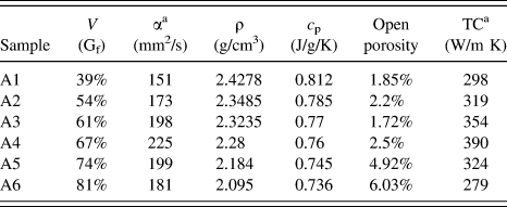
Table II summarizes the thermo-physical properties of Gf/Si/Al composites. The TC of Gf/Si/Al composites in X–Y plane is much higher than that of in the z direction. Here, attention is focused on the TC in X–Y plane of the composites. The measured longitudinal TC of the oriented composites increases from 298 to 390 W/m K with an increase of the graphite from 39 to 81 vol%.
Thermo-physical properties of the obtained Gf/Si/Al composites.
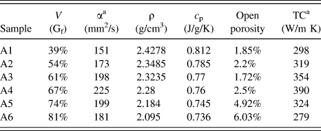
a Parallel to the graphite layers.
Based on the assumed microstructure of alternating layers of Gf and ZAlSi7Mg–Sip composites, traditional prediction of TC depends on the layers-in-parallel modelReference Truong and Zinsmeister22 without considering the interface thermal resistance. The layers-in-parallel model considers heat-transfer characteristics parallel to the major heat flow direction of layered composites (see Fig. 7). The model is described as follows:
 $$k_{\rm{l}}^{\rm{c}} = f{k_{\rm{l}}} + \left( {1 - f} \right){k_{\rm{m}}}\quad ,$$
where  $k_{\rm{l}}^{\rm{c}}$, k l, and k m refer to the longitudinal TC of composites, Gf and matrix, respectively. And f is the volume fraction of graphite. It should be noted here that the TC of ZAlSi7Mg (151 W/m K) is almost the same as the TC of Si (150 W/m K), simultaneously the volume fraction of Si is very low, so Si can be ignored when calculating the TC of composite in Eq. (4). To take into account the effect of interfacial thermal resistance, a joint M1–M2 prediction of the TC in X–Y plane, by means of combining the Hasselman–JohnsonReference Hasselman and Johnson23 and Hatta–TayaReference Hiroshi and Minoru24 modes, is plotted versus the experimental data in Fig. 8.
The schematic diagram of two different models.
Comparison of experimental data with two different theoretical predictions.
In this work, the TC will be calculated following a two-step process. First, the TC of the two-phase composites (ZAlSi7Mg)–(Sip) will be calculated, and the second step will deal with again another two-phase composites (Gf)–(ZAlSi7Mg–Sip), whose morphology will be described by means of models M1 and M2.
1. The model of M1
In the binary ZAlSi7Mg–Sip composites (k mp), a suitable approach takes into account the effect of interfacial thermal resistance of Al alloy–Si particles by Hasselman–Johnson.Reference Hasselman and Johnson23 The TC can be expressed as M1 (see Fig. 7):
 $${k_{{\rm{mp}}}} = {{{k_{\rm{m}}}\left[ {2{k_{\rm{m}}} + k_{\rm{p}}^{{\rm{eff}}} + 2\left( {k_{\rm{p}}^{{\rm{eff}}} - {k_{\rm{m}}}} \right) \cdot {x_{\rm{p}}}} \right]} \over {2{k_{\rm{m}}} + k_{\rm{p}}^{{\rm{eff}}} - \left( {k_{\rm{p}}^{{\rm{eff}}} - {k_{\rm{m}}}} \right) \cdot {x_{\rm{p}}}}}\quad ,$$
where k m is the TC of the Al alloy and x p is the volume fractions of Si particles in the binary ZAlSi7Mg–Sip composites,  $k_{\rm{p}}^{{\rm{eff}}}$ is the effective TC of the Si particles that is defined as:
 $$k_{\rm{p}}^{{\rm{eff}}} = {{{k_{\rm{p}}}} \over {1 + {{{k_{\rm{p}}}} \over {a \cdot {h_{{\rm{mp}}}}}}}}\quad ,$$
where k p stands for the intrinsic TC of the Si particles and a and h mp are the average radius of Si particles and the interfacial thermal conductance of the Al–Si particles interface, respectively. Assuming that heat is transported entirely by phonons and ignoring the influence of electron, the interfacial thermal conductance h can be estimated by the acoustic mismatch model (AMM)Reference Liu, He, Ren, Zhang, Liu and Qu25:
 $$h \cong {1 \over 2}{\rho _{\rm{m}}}{C_{\rm{m}}}{{v_{\rm{m}}^3} \over {v_{\rm{i}}^2}}{{{\rho _{\rm{m}}}{v_{\rm{m}}}{\rho _{\rm{i}}}{v_{\rm{i}}}} \over {{{\left( {{\rho _{\rm{m}}}{v_{\rm{m}}} + {\rho _{\rm{i}}}{v_{\rm{i}}}} \right)}^2}}}\quad ,$$
where ρ, C, and v are the density, the specific heat capacity, and the phonon velocity, respectively; subscripts m and i denote the matrix and the inclusion, respectively. v m is the Debye phonon velocity of Si calculated by Table I. Here, we replace ZAlSi7Mg with pure Al due to the lack of Debye phonon velocity of ZAlSi7Mg. The results of calculation are as follows: h mp = 2.8 × 10⁷ W/m2 K [from Eq. (7)],  $k_{\rm{p}}^{{\rm{eff}}} = 147.885\,{{\rm{W}} \mathord{\left/ {\vphantom {{\rm{W}} {{\rm{m}}\;{\rm{K}}}}} \right. \kern-\nulldelimiterspace} {{\rm{m}}\;{\rm{K}}}}$ [from Eq. (6)].
As remarked above, a set of optimized thermal diffusion coefficients of binary ZAlSi7Mg–Sip composites can be obtained according to the different proportion of Si and aluminum matrix (k mp). Details are reported in Table III.
The thermo-physical properties of the obtained Gf/Si/Al compositesa.
a  $k_{\rm{c}}^1$ is obtained from parallel layered model.
 $k_{\rm{c}}^2$ is obtained from the joint M1–M2 model.
2. The model of M2
Once the TC of the ZAlSi7Mg–Sip composites has been calculated, the problem is simplified to compute the TC of the composites (Gf–ZAlSi7Mg–Sip). The method proposed by Hatta–Taya, which assumes that the reinforcements are oriented thin flakes homogenously distributed in the matrix.Reference Hiroshi and Minoru24 Then, the M2 model (see Fig. 7) can be expressed as:
 $${k_{\rm{c}}} = {k_{{\rm{mp}}}}\left[ {1 + {{{V_{\rm{f}}}} \over {{{\pi t} \over {4D}}\left( {1 - {V_{\rm{f}}}} \right) + {{{k_{{\rm{mp}}}}} \over {k_{\rm{f}}^{\rm{e}} - {k_{{\rm{mp}}}}}}}}} \right]\quad ,$$
where V f is the volume fraction of the graphite flakes, t and D are the thickness and diameter of the Gf, respectively, k mp is the TC of the ZAlSi7Mg–Sip and  $k_{\rm{f}}^{\rm{e}}$ is the effective basal plane TC of the flakes which can be obtained from the mixture rule for a simple series model of interface barrier/flake/interface-barrier that is defined as:
 $$k_{\rm{f}}^{\rm{e}} = {{{k_{\rm{f}}}} \over {1 + {{{k_{\rm{f}}}} \over {a \cdot {h_{{\rm{fmp}}}}}}}}\quad ,$$
where k f stands for the intrinsic basal plane TC of the flakes, which is taken as 1000 W/m K, and h fmp stands for the interfacial thermal conductance between Gf and ZAlSi7Mg–Sip.
Cong Zhou et al.Reference Zhou, Ji, Chen, Wang, Addad, Schryvers and Wang13 found that no reactions occur at the side surface of Gf/Al interface and the influence of the amorphous carbon layer on the TC of the composites is negligible since the layer thickness (5–8 nm) is much smaller than the diameter of Gf [500 µm, see Fig. 1(a)]. Due to the lack of data for ZAlSi7Mg, pure Al is considered here for theoretical calculations. The correlative parameters for the calculation are given in Table I. The results of calculation are as follows: h fmp = 4.3 × 10⁷ W/m2 K [from Eq. (7)],  $k_{\rm{f}}^{\rm{e}} = 915.75\,{{\rm{W}} \mathord{\left/ {\vphantom {{\rm{W}} {{\rm{m}}\;{\rm{K}}}}} \right. \kern-\nulldelimiterspace} {{\rm{m}}\;{\rm{K}}}}$ [from Eq. (9)]. Finally, we combine the model of M1 with M2 to get the final prediction value of the composites according to Eq. (8).
3. Thermal conductivity
As shown in Fig. 8, the experimental results basically agree with the model curve in tendency except the obvious decrease of the high volume fraction of graphite. Compared with the joint M1–M2 model, the traditional layers-in-parallel model obviously overestimates the TC of the Gf/Si/Al composites with increasing volume fraction of graphite. Clearly, the joint M1–M2 model has a better predictive capacity as compared to the traditional one.
There is a remaining deviation between the experimental results and theoretical predictions, which may be attributed to the following facts. Firstly, despite in the vacuum atmosphere, the gas will inevitably be drawn into and hard to overflow, resulting in the porous and loose composites. However, the coefficient of TC of air is very low, thus the heat flow will be hindered through the air, which will reduce the TC and density of composites. Qian Liu et al.Reference Liu, He, Ren, Zhang, Liu and Qu25 consider that there is a small amount of oxygen in the region of interface, which may cause the lattice phonon dissipation, resulting in a decrease of thermal interfacial conductance and degradation of the TC. Secondly, the thickness of graphite flakes and diameter of Si particles are not uniform and this thickness variation as well as the aspect ratio of the inclusion phase can have an effect on TC of the composites.Reference Zhou, Ji, Chen, Wang, Addad, Schryvers and Wang13 Thirdly, the amount of curved flakes increases with increasing volume fraction of Gf, which could deflect flow of heat and lead to a decrease on thermal property of composites.Reference Chen and Huang26 Besides, the residual pore-forming agent (urea) as impurities will also hinder the conduction of heat flow due to its low TC (only 79.91 W/m K), resulting in an increase of thermal interfacial resistance and degradation of the TC, which is very similar to the effect of air in voids. Finally, in this experiment, the irregular shape of Si and the way of mechanical addition lead to inhomogeneous distribution in the composites. A small amount of Si to the aluminum alloy can reduce the solubility of carbon in the aluminum, thus effectively inhibit the formation of Al4C3. Therefore, obtaining a uniform distribution of Si and exploring the interfacial combination of Si and aluminum matrix deserve a deep research.
IV. CONCLUSION
In summary, hybrid aluminum matrix composites reinforced with Si and graphite flakes (Gf/Si/Al) were fabricated by using the vacuum gas pressure infiltration process. The results obtained in this paper are as follows:
(1) Using Si particles as a second phase and ZAlSi7Mg as the metallic alloy allow to obtain longitudinal TC within the range 294–390 W/(m K).
(2) Under a vacuum of 2 MPa, the porous preform was infiltrated by molten aluminum alloy at 720 °C for 5 s. This optimized condition can contribute to avoid the formation of Al4C3.
(3) The addition of Si particles played a role of spacing apart graphite layers, which can produce more voids between layers for the infiltration of molten aluminum and improve the interface between Al and Gf.
(4) The joint M1–M2 model, which considered that the microstructure of Gf/Si/Al composites lies in between two perfect models: (M1) an idealized layered structure in binary metal-particle composites and (M2) ternary composites that oriented lakes randomly distributed in metal-particle confirmed a better theoretical prediction of longitudinal TC than traditional layers-in-parallel model.
ACKNOWLEDGMENT
This research was financially supported by the Natural Science Foundation of Shaanxi Province (Grant No. 2015JZ014).