Introduction
Solid electrolytes are promising candidates to replace conventional liquid electrolytes in energy storages. They can suppress formation of dendrite in Li- or Na-ion batteries[Reference Masquelier1, Reference Tarascon and Armand2] and hinder the shuttle effect (migration of soluble Li polysulfide from the cathode to anode) in Li–S batteries.[Reference Hassoun and Scrosati3, Reference Zhong, Wang, Xu, Ding and Liu4] Over the past years, lithium garnet oxide conductors have attracted an increasing interest as solid electrolytes due to their high Li ion conductivities as well as stabilities.[Reference Thangadurai, Kaack and Weppner5–Reference Thangadurai and Weppner7] Cubic-Li7La3Zr2O12 (hereafter called LLZO) which has been synthesized for the first time by Murugan et al.[Reference Murugan, Thangadurai and Weppner8] has a lithium ionic conductivity of ~10−4 Scm−1 at room temperature.[Reference Awaka, Takashima, Kataoka, Kijima, Idemoto and Akimoto9–Reference Wang and Lai12] In addition, LLZO has a relatively high stability against metallic lithium.[Reference Zhu, He and Mo13–Reference Thompson, Yu, Williams, Schmidt, Garcia-Mendez, Wolfenstine, Allen, Kioupakis, Siegel and Sakamoto15] Thus, LLZO is one of the most promising electrolyte materials in energy research. On the other hand, LiCoO2 (LCO) with a theoretical capacity of about 274 mA h g−1 is widely used as a cathode material in Li-based batteries.[Reference Koksbang, Barker, Shi and Saidi16–Reference Ohzuku and Ueda19] LCO is an oxide-based lithium intercalation compound, and it has been the subject of extensive studies owing to its high-volume energy density and excellent cycle life.[Reference Koksbang, Barker, Shi and Saidi16, Reference Du Pasquier, Plitz, Menocal and Amatucci20] Therefore, many experimental studies have been carried out to construct a Li-based battery with LLZO as the solid electrolyte, LCO as the cathode, and Li as the anode material. In spite of a relatively high Li conductivity of LLZO, batteries constructed from these garnet materials have not been commercialized yet. Many experimental studies have reported a high interfacial resistance between LLZO and electrode materials.[Reference Ren, Liu, Shen, Lin and Nan21, Reference Takada, Ohta, Zhang, Fukuda, Sakaguchi, Ma, Osada and Sasaki22] Using transmission electron microscopy (TEM) and energy dispersive x-ray spectroscopy, Kim et al.[Reference Kim, Iriyama, Yamamoto, Kumazaki, Asaka, Tanabe, Fisher, Hirayama, Murugan and Ogumi23] have found a strong interaction at the interface between LLZO and LCO during the high-temperature process of LCO coating on LLZO. Cation interchange and/or formation of new phases such as La2CoO4 have been reported.[Reference Kim, Iriyama, Yamamoto, Kumazaki, Asaka, Tanabe, Fisher, Hirayama, Murugan and Ogumi23] Furthermore, in x-ray diffraction patterns and TEM images, Park et al.[Reference Park, Yu, Jung, Li, Zhou, Gao, Son and Goodenough24] have observed cation interchange and formation of tetragonal-LLZO phase during a high-temperature process to fuse LCO and cubic-LLZO.
There are few theoretical studies on the electrode/electrolyte interfaces in all solid-state batteries. Using ab initio molecular dynamics simulations, Ohno et al.[Reference Sumita, Tanaka, Ikeda and Ohno25] have studied Li3PO4/LiFePO4 interface and reported that Li can diffuse from the first layer of LiFePO4 to the electrolyte (Li3PO4). In another research, Ohno et al.[Reference Sumita, Tanaka, Ikeda and Ohno26] have also reported on the formation of a Li-depleted layer at the electrolyte side (sulfide side) of the Li3PS4/LiFePO4 interface. Haruyama et al.[Reference Haruyama, Sodeyama, Han, Takada and Tateyama27] have studied the influence of a LiNbO3 buffer layer on β-Li3PS4/LCO interface using density functional theory (DFT). They have found that Li ions adsorb at the oxygen sites of LCO, leading to the space-charge-layer formation. However, the LiNbO3 interlayer suppresses the growth of the space-charge layer at LCO.[Reference Haruyama, Sodeyama, Han, Takada and Tateyama27] Due to the large size of the LLZO unit cell and number of electrons, DFT calculation for the LLZO/LCO interface is challenging. In this work, we model and study, for the first time, electronic and atomic structure as well as ion distribution at an ideal interface between LLZO and LCO, namely LLZO(001)/LCO(10–14), which might form at low-temperature processing. Study of cation interchange and formation of new phases at LLZO/LCO interfaces will be the subject of our future studies.
Methods
All calculations are performed using mixed Gaussian and plane-wave code CP2K Quickstep[Reference Lippert, Hutter and Parrinello28–Reference VandeVondele, Krack, Mohamed, Parrinello, Chassaing and Hutter31] at the DFT level of theory using Perdew–Burke–Ernzerhof[Reference Perdew, Burke and Ernzerhof32] + Hubbard U parameter exchange–correlation functional (Dudarev method[Reference Dudarev, Botton, Savrasov, Humphreys and Sutton33]). Different values of effective on-site Coulomb repulsion U′ = U – J are explored for Co cations. It is found that the value U′ = 5.8 eV gives a band gap (BG) of 2.3 eV for LCO, which lies in the experimental range of values between 1.7 and 2.7 eV.[Reference Ghosh, Mahanty, Raja, Basu and Maiti34–Reference Van Elp, Wieland, Eskes, Kuiper, Sawatzky, De Groot and Turner37] The small number of electrons in the d electronic shell of La and Zr (one and two electrons, respectively) results in a weak on-site Coulomb repulsion. Therefore, U’ is usually not included in DFT calculations for La and Zr in LLZO.[Reference Miara, Ong, Mo, Richards, Park, Lee, Lee and Ceder38–Reference Meier, Laino and Curioni42] We have also not considered U’ for these cations. The computations are carried out through unconstrained diagonalization of the Kohn–Sham Hamiltonian (spin-polarized) along with Goedecker–Teter–Hutter pseudopotentials to represent the core electrons.[Reference Goedecker, Teter and Hutter43] The number of considered valence electrons for Li, O, La, Zr, and Co are 3, 6, 11, 12, and 17, respectively. Because of a large number of electrons in our model system (3680 electrons) we use single-zeta basis set to reduce the computational cost of calculating structures and energies of LLZO(001) and LCO(10–14) interfaces. The plane wave energy cutoff is set to 340 Ry and Brillouin zone sampling is carried out by a Γ-point sampling.
Our calculated bulk LLZO structure has a lattice parameter of a = 12.998 Å, which is similar to the theoretical value of 12.983 Å reported by Meier et al.[Reference Meier, Laino and Curioni42] as well as the experimental value of 12.968 Å.[Reference Murugan, Thangadurai and Weppner8] In the case of LCO, the computed lattice parameters of a = b = 2.862 Å and c = 14.045 Å are also in fair agreement with theoretical values of a = b = 2.829 Å and c = 14.119 Å,[Reference Ensling, Thissen, Laubach, Schmidt and Jaegermann44] and experimental values of a = b = 2.819 Å and c = 14.09 Å.[Reference Rodrigues, Wontcheu and MacNeil45] The LLZO(001) surface is modeled by a two bulk unit-cell thickness with 384 atoms. The modeled LLZO(001)/LCO(10–14) interface consists of 544 atoms in total. Two bottom layers of LCO(10–14) as well as bottom 6.35 Å of LLZO(001) slabs are fixed at the bulk-truncated coordinates.
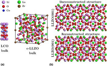
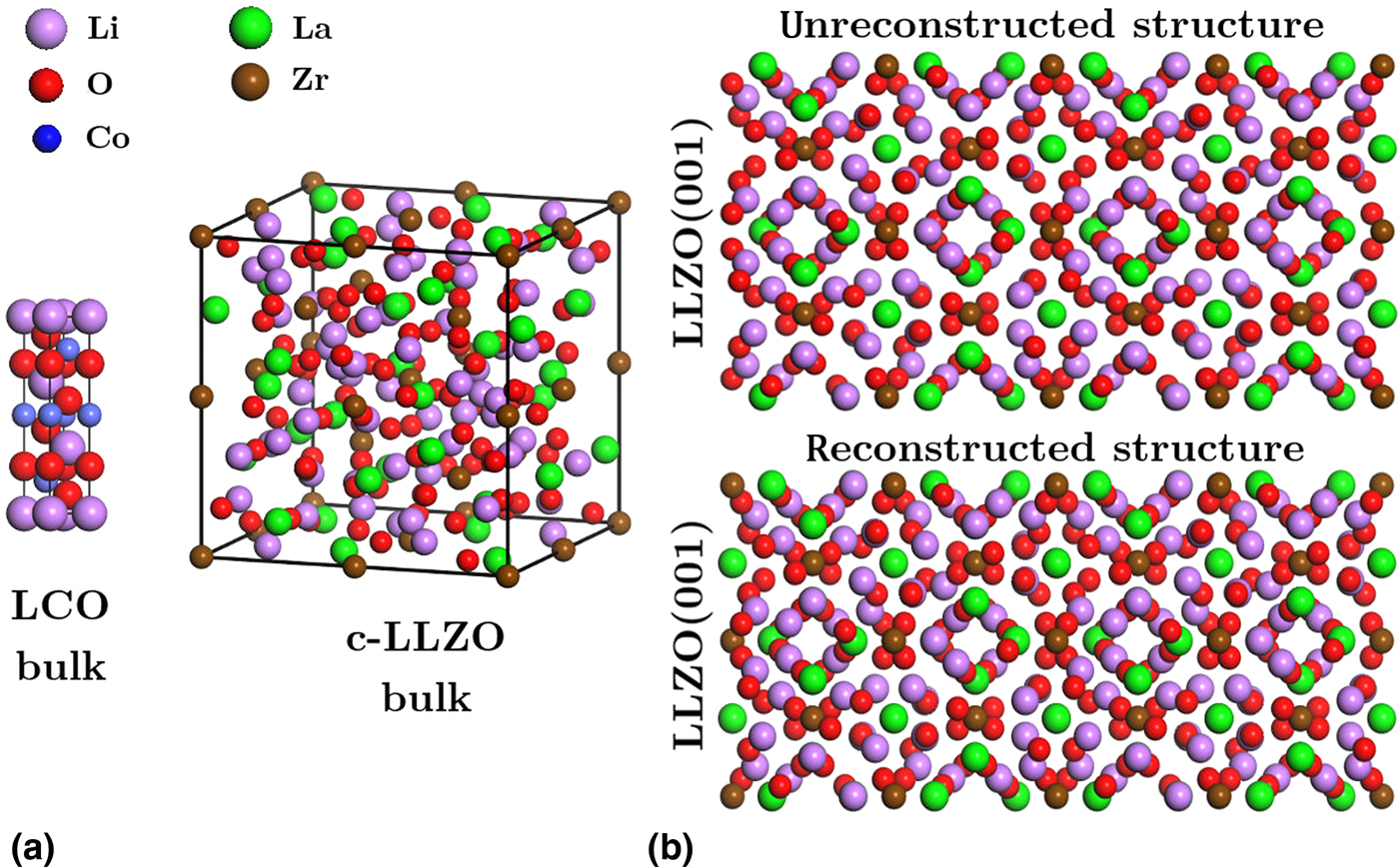
Structures of bulk LLZO and LCO are illustrated in Fig. 1(a). Bulk structure of LLZO is modeled considering the site occupancies suggested by Awaka et al.[Reference Awaka, Takashima, Kataoka, Kijima, Idemoto and Akimoto9]. In this structure, the occupation of adjacent Li sites by Li ions is excluded. Our calculations show that the pristine stoichiometric LLZO(001) surface is energetically unfavorable because of its asymmetric arrangement of surface ions: the structure is terminated with Zr and La cations at one side, but not at the other side. To stabilize this structure, we consider a reconstructed surface by moving two surface Zr and two surface La cations (per 1 × 1 unit-cell) from one side to the other side [see Fig. 1(b)]. A similar reconstruction has been found in simpler ionic crystals such as rock salt structures.[Reference Panahian Jand and Kaghazchi46] The reconstructed LLZO(001) surface is then used to construct the interfaces.
Atomic structures of (a) bulk LCO and LLZO as well as (b) unreconstructed and reconstructed LLZO(001) surfaces.
Results and discussion
Previous theoretical studies show that LCO(10–14) and LCO(0001) are the most favorable surfaces of LCO under a wide range of Li and O chemical potentials.[Reference Okubo, Hosono, Kim, Enomoto, Kojima, Kudo, Zhou and Honma47, Reference Kramer and Ceder48] In this work, we consider the former surface where the Li layers are extended from the surface to the bulk region. The low-index LLZO(001) surface with a rectangular unit cell is chosen to match with the LCO(10–14) surface in the interface slab. To investigate the effect of lattice mismatch between LLZO(001) and LCO(10–14), we consider three interface models with different lattice parameters: (I) a = b = 12.99 Å [the theoretical unit cell of LLZO(001)], (II) a = 12.23 Å and b = 12.22 Å [the averaged unit cell of LLZO(001) and LCO(10–14)], and (III) a = 11.46 Å and b = 11.45 Å [the theoretical unit cell of LCO(10–14)].
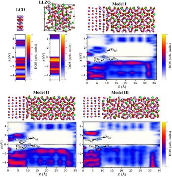
The most favorable structures of LLZO(001)/LCO(10–14) interfaces (models I–III) are presented in Fig. 2. More details on the interface construction and the computation parts can be found in supplementary information. We find that atomic structures of bulk region of LLZO(001) and LCO(10–14) remain bulk-like in models I and II, but not in model III where the unit cell of LCO(10–14) is applied. The strongest interaction energy, subtraction of total energy of separated slabs from that of the interface, is obtained for model I (−15.19 eV) which is 8.43 and 9.45 eV stronger than that of models II and III, respectively.
Atomic structures and density of states for bulk LCO and LLZO as well as different interface models. Fermi level is set to 0 eV.

Regarding model I, we find that geometry optimization leads to a small electron transfer of 0.48e as well as one Li+ from LCO to LLZO. A similar result is also obtained for model II where one Li+ and 0.28e transfer from LCO to LLZO. In model III, no ionic transfer occurs, but 0.80e electron transfers from LCO to LLZO. To find which ions and orbitals participate in electron transfer, we plot electron density of states (DOS) for bulk LCO, bulk LLZO and LCO(10–14)/LLZO(001) interface models along the interface normal direction (z) (see Fig. 2). We also calculate projected DOS per atom and angular momentum and label accordingly the gap states in the DOS plots. Figure 2 indicates that in model I, the gap states in LCO(10–14) between −0.3 and 0.3 eV LCO(10–14) are due to the Co3d and O2p orbitals, while those between −1 and 0.3 eV in LLZO(001) are due to O2p orbitals. Moreover, it is shown that electron/hole transfer is extended from the first layer to the second and even third layer of LCO(10–14) (in a range of 3 Å). However, charge transfer in LLZO(001) is limited to about 2 Å. In model I, in which biaxial tensile strain is the largest for LCO(10–14) (a = 13.4% and b = 13.5%) Co cations and O anions in LCO(10–14) receive and also donate electron depending on the nearby ions at the surface of LLZO(001), and, therefore, the Fermi level cuts through the gap states in LCO. However, O anions receive and Zr cations donate electron in LLZO(001). BG of LCO in model I is smaller than that in model II (due to the larger tensile strain in model I), and therefore a larger electron transfer occurs from LCO to LLZO in the former case (model I, 0.48e; model II, 0.28e). In model II in which tensile strain for LCO(10–14) (a = 6.7% and b = 6.8%) and compressive strain for LLZO(001) (a = 5.9% and b = 6.0%) are moderate, created and occupied states in LCO and LLZO are similar to those in model I. Small empty states just above the Fermi level are due to O2p. In this case, the empty Co3d states are close to the valence band maximum. In model III in which tensile strain for LCO(10–14) is zero and compressive strain for LLZO(001) (a = 11.8% and b = 11.9%) is large, the atomic structure of LLZO(001) becomes disordered. Similar to model II, the created empty states are due to Zr4d and Co3d. The created occupied states are merged to the valence band maximum of both surfaces.
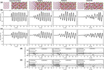
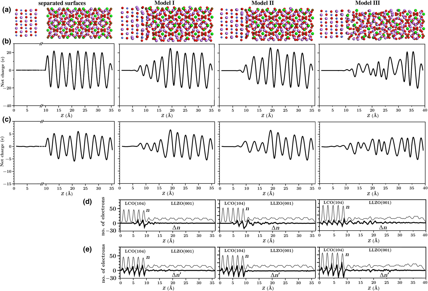
To study ionic charge redistribution at the LLZO(001)/LCO(10–14) interface, we calculate ionic charge q(z) using oxidation states and Mulliken charge analysis as function of z (along the normal of the interface) with a mapped column width of ~1 Å as a typical size of ions. Since both methods give a similar q(z) [Figs. 3(b) and 3(c)], in the following, we only discuss q(z) based on the Mulliken charge analysis. Figure 3(c) indicates that in the case of separated surfaces, there is a sequential chain of dipoles along the z-direction for both LCO(10–14) and LLZO(001). The dipoles are, however, much larger in the latter case. When bringing the surfaces in contact with each other, the dipole moments become weaker at top-most layers of the LLZO(001) surface, while they become stronger at outer-most layers of LCO(10–14) surface in the interface models I and II. The change in dipole moments (i.e. charge distribution) in LLZO extends to a distance of ~8 Å from the interface while it is up to ~3 Å in LCO. The increase in dipole moments at the surface of LCO(10–14) is due to the displacements of Li, Co, and O ions close to the surface. In addition, the decrease in dipole moments at LLZO(001) is a result of Li and O rearrangements. The electron difference (Δn) in Fig. 3(d) is the difference in the number of electrons (calculated from the electron density multiplied by volume elements of 0.17 × 0.17 × 0.17 Å3) at the interface and separated surfaces before the interface construction. Figure 3(d) plots also confirm the increase in dipole moments at LCO(10–14), but not the decrease in dipole moments at LLZO(001). Therefore, we conclude that the latter effect is due to a complex rearrangement of ions rather than displacement of electrons. In Fig. 3(e), Δn ′ shows the difference of number of electrons at the interface and separated surfaces (obtained by single point energy calculation for the surfaces from the relaxed interfaces). The Δn ′ plots demonstrate the formation of dipole moments at LCO(10–14) which is due to a displacement of electrons toward the bottom of the surface. The electron displacement-induced dipole moments adds to the ionic displacement-induced dipole moments at LCO(10–14).
(a) Atomic structures for separated surfaces and different studied interface models. Ionic charge diagrams calculated by (b) oxidation state and (c) Mulliken population analysis. (d) Number of electrons (n) for the LLZO(001)/LCO(10–14) interfaces as well as the difference between n of the interfaces and separated relaxed surfaces before bringing them in contact with each other (Δn) as function of z. (e) The difference between n of the interfaces and separated surfaces with the same geometry as that of the relaxed interfaces (Δn ′) as function of z.
To further study the possibility of accumulation of Li ions at the interface, we move two Li ions from z = 26.8 Å (middle) to z = 14.7 Å (top-most layers) within the LLZO(001) slab considering model II. Among eight different considered configurations, four structures are energetically more favorable than the pristine interface (by 0.33–1.38 eV). In these structures, one Li ion fills the vacant Li site at the surface of LCO(10–14), which has been created spontaneously by geometry optimization of pristine interface, and another Li ion occupies an interstitial site in LLZO(001) close to an oxygen anion of the LCO(10–14) surface. Moreover, we move two Li ions from the top of LCO to the top of LLZO(001) slab at the interface in model II. Four different possible configurations are tested, and the most stable structure is found to be 0.3 eV more favorable than the pristine interface. During geometry optimization, one Li ion comes back to the vacant Li site in LCO, while the other Li ion remains in an interstitial site of LLZO bonding with O of LCO. This result shows accumulation of Li ions at the interface plane is energetically favorable. We also carry out a similar investigation for O anions but none of the structures is energetically more favorable than the pristine interface.
Conclusions
We have studied the LLZO(001)/LCO(10–14) interface as a model system for the electrolyte/electrode interface in all solid-state batteries using DFT calculations. The interface was modeled by considering different magnitudes of biaxial compressive and tensile strains. It has been shown that LCO(10–14) remains crystalline even under a large biaxial tensile strains of 13.5% (model I). Both LCO(10–14) and LLZO(001) remain crystalline under moderate strains of 6.8% and 6.0% (model II). However, the LLZO(001) surface becomes disordered under a large biaxial compressive strain of 11.9% (model III). It was found that geometry optimization of the interface models of I and II leads to spontaneous Li transfer from LCO to LLZO. Along this process, partial electron is transferred from LCO to LLZO. However, the ion and electron transfers do not compensate completely each other leading to the formation of dipole at the interface. Due to a large computational cost and time, ab initio molecular dynamics for this system is not possible. To study possibility of accumulation of more number of Li ions at the LLZO(001)/LCO(10–14) interface, we chose model II and consider transfer of Li ions from deep layers of LLZO to the topmost layers of LLZO. Our calculations showed that accumulation of Li ions at the interface is energetically favorable. The accumulated Li ions at the interface occupy interstitial sites close to the O anions of LCO, showing an electrostatic driving force for this process. The presented approach to model the LCO/LLZO interface can be used to study other complex solid/solid interfaces in all solid-state batteries, solid fuel cells, and heterogeneous solar cells.
Supplementary material
The supplementary material for this article can be found at https://doi.org/10.1557/mrc.2018.33
Acknowledgments
The authors gratefully acknowledge support from the “Bundesministerium für Bildung und Forschung” (BMBF), and the computing time granted on Zentraleinrichtung für Datenverarbeitung (ZEDAT) at the Freie Universität Berlin. The authors also acknowledge the North-German Supercomputing Alliance (HLRN) for providing high-performance computing resources that have contributed to the research results reported in this paper.