1. Introduction
Flow fields of interest contain a broad range of coherent flow structures undergoing nonlinear interactions. Recent advances in computational and experimental techniques have generated high-fidelity representations of these dynamics in the form of enormous databases. The extraction of knowledge from such high-dimensional fields is greatly facilitated by modal decomposition, which is playing an increasingly crucial role in discerning the relevant kinematic and dynamic flow features. Modal decomposition describes the spatiotemporally varying flow field in terms of spatially correlated, or coherent, flow features ordered by some property such as energy content or growth rate, together with their temporal variation.
Some of the commonly used modal decomposition techniques have been recently reviewed by Rowley & Dawson (Reference Rowley and Dawson2017) and Taira et al. (Reference Taira, Brunton, Dawson, Rowley, Colonius, McKeon, Schmidt, Gordeyev, Theofilis and Ukeiley2017, Reference Taira, Hemati, Brunton, Sun, Duraisamy, Bagheri, Dawson and Yeh2020). Among these, the most popular are proper orthogonal decomposition (POD) and dynamic mode decomposition (DMD). In these, data from high-fidelity numerical or experimental efforts are a posteriori processed to extract a set of (in POD) energetically ranked orthogonal modes (Kosambi Reference Kosambi1943; Karhunen Reference Karhunen1946; Loeve Reference Loeve1948) or (in DMD) dynamically significant modes (Rowley et al. Reference Rowley, Mezić, Bagheri, Schlatter and Henningson2009; Schmid, Meyer & Pust Reference Schmid, Meyer and Pust2009; Schmid Reference Schmid2010), each with associated temporal dynamics. Other ways of assessing these modes include their energies and growth/decay rates. POD is optimal among all decompositions in terms of the maximization of energy for a given number of modes (Berkooz, Holmes & Lumley Reference Berkooz, Holmes and Lumley1993). The corresponding temporal coefficients are closely linked to the spatial modes, resulting in a bi-orthogonal decomposition (Aubry, Guyonnet & Lima Reference Aubry, Guyonnet and Lima1991; Shinde Reference Shinde2020). DMD, on the other hand, provides modes that are associated with unique frequencies and growth or decay rates. It is based on Koopman theory (Koopman Reference Koopman1931), whose connection to aspects of the Koopman operator/modes has been developed in Mezić (Reference Mezić2005, Reference Mezić2013) and to DMD modes as illustrated in Rowley et al. (Reference Rowley, Mezić, Bagheri, Schlatter and Henningson2009). Although both POD and DMD are linear procedures, the underlying dynamics of the system that generated the flow fields may be nonlinear.
Most decomposition techniques are formulated and applied in the Eulerian (fixed) frame of reference, which complicates their application in deforming or moving domains. An example is the problem of fluid–structure interactions where structural response causes boundary shape changes with corresponding mesh deformation. This difficulty has been recognized in the literature as, for instance, by Mohan, Gaitonde & Visbal (Reference Mohan, Gaitonde and Visbal2016) and Menon & Mittal (Reference Menon and Mittal2020), who performed DMD of pitching/plunging airfoils. One solution is to simplify the application by restricting attention to a part of the domain, as in Schmid (Reference Schmid2010), Goza & Colonius (Reference Goza and Colonius2018) and Shinde et al. (Reference Shinde, McNamara, Gaitonde, Barnes and Visbal2019b), who used POD and DMD for fluid–structure interactions. A method that factors mesh deformation is presented by Shinde et al. (Reference Shinde, Longatte, Baj, Hoarau and Braza2019a), who obtained POD modes on deforming mesh solutions in the context of reduced-order modelling of vortex-induced vibration and supersonic flutter. Nevertheless, a formal mathematical framework for modal decomposition on deforming and moving domains applicable to fluid flow analysis remains a pressing need. To address this gap, we develop a Lagrangian modal analysis (LMA) approach that eases application of modal decomposition techniques to flows involving domain deformation, by recasting the analysis in a suitably selected moving reference frame. The formulation is couched in general terms, though, for concreteness, we consider both Lagrangian proper orthogonal decomposition (LPOD) as well as Lagrangian dynamic mode decomposition (LDMD).
An important practical difference between the Eulerian and Lagrangian descriptions lies in the number of variables required to represent the flow (Price Reference Price2006). For example, a steady non-uniform flow in the Eulerian (fixed-point) representation is time-dependent in the Lagrangian formulation. The difference between the reference frames manifests in the definition of acceleration and is related to spatial velocity gradients in the flow. Thus, the Eulerian (local) acceleration for a steady non-uniform flow is zero, whereas the Lagrangian (convective) acceleration remains non-zero. In the present work, we exploit this Lagrangian time dependence of steady non-uniform flows, to pose modal decompositions in the Lagrangian frame of reference. The significance of Lagrangian modal analysis of an otherwise steady (Eulerian) base flow is also discussed from the standpoint of flow stability.
A natural question arises on the connection between LMA and Lagrangian techniques employed in chaos and mixing studies. In particular, Lyapunov exponents are commonly used to quantify the divergence or stretching of a filament in time, and are related to specific stretching rates and mixing efficiencies (Ottino Reference Ottino1989). The relatively popular finite-time Lyapunov exponent (FTLE) technique invokes a Lagrangian frame of reference and has been employed for a variety of assessments (Haller & Yuan Reference Haller and Yuan2000; Shadden, Lekien & Marsden Reference Shadden, Lekien and Marsden2005; Peacock & Dabiri Reference Peacock and Dabiri2010; Mancho et al. Reference Mancho, Wiggins, Curbelo and Mendoza2013; Samelson Reference Samelson2013; Haller Reference Haller2015; Nelson & Jacobs Reference Nelson and Jacobs2015; González et al. Reference González, Speth, Gaitonde and Lewis2016). The largest such exponent identifies high-strain regions exhibiting stable/unstable manifolds or hyperbolic trajectories (Balasuriya, Kalampattel & Ouellette Reference Balasuriya, Kalampattel and Ouellette2016). The present LMA aims to decompose the stretching of the flow fabric into coherent modes pertaining to the specific modal decomposition technique (in our case, POD or DMD). Thus, the largest FTLE, which represents the largest eigenvalue of the right Cauchy–Green strain tensor, is analogous to the first Lagrangian POD mode. We establish this correspondence in general terms through a mathematical relation between the FTLE and Lagrangian modal analysis ansatz.
To demonstrate LPOD and LDMD, we consider two canonical flow configurations, namely, a lid-driven cavity and flow past a cylinder, representing, respectively, an internal and an external flow. Direct numerical simulations (DNS) are performed for each in the Eulerian frame of reference at  $M_\infty =0.5$ by solving the compressible Navier–Stokes equations. A range of Reynolds numbers is considered for each to encompass steady (pre-critical) and unsteady (post-critical) regimes. For the lid-driven cavity, the first Hopf bifurcation occurs at
 $Re_L\approx 10\,500$, where
 $Re_L$ is the Reynolds numbers based on the cavity length. Thus the range chosen is
 $5000 \leq Re_L \leq 15\,000$. A suitable surrogate representing key properties of fluid–structure interactions is constructed by subjecting the lid-driven cavity to a forced-domain deformation. The flow past a cylinder considers the Reynolds number (based on the cylinder diameter,
 $D$) range between
 $20 \leq Re_D \leq 100$, encompassing the first Hopf bifurcation at
 $Re_c\approx 50$. A simple analytical model of the double-gyre flow pattern is used to examine the mathematical link derived between the FTLE and the LPOD and LDMD modes.
The article is organized as follows. Next, § 2 presents the theoretical framework for the LMA, which includes (i) transformation of the Eulerian flow fields to the Lagrangian flow fields, (ii) formulation of the LPOD and LDMD, and (iii) the derivation of the mathematical link between the FTLE and LMA. The details of the numerical methodology and case studies are provided in § 3. The results and discussion section (§ 4) presents the application of LMA to the different flow types, namely, unsteady flow, flow with mesh deformation, Eulerian steady but Lagrangian unsteady flow, and the double-gyre case study elucidating the relation with FTLE. Lastly, we provide some concluding remarks in § 5.
2. Theory
The Lagrangian (moving) and Eulerian (fixed) descriptions of fluid flow are necessarily equivalent in terms of the dynamics. Although the Lagrangian perspective offers some mathematical and conceptual advantages, the lack of direct access to spatial velocity gradients poses difficulties for the solution of Navier–Stokes equations (Batchelor Reference Batchelor2000). The Eulerian perspective is more convenient, such as, for example, in the comparison with fixed-point measurements obtained from experiment, and is thus commonly employed for flow simulations. In the same vein, modal decomposition techniques such as POD and DMD have been developed for the Eulerian description. In the present work, we retain the Eulerian approach to simulate the flow, but the data are then recast into a suitable Lagrangian frame that is more convenient for the application of modal analysis techniques, even when the domain is deforming.
2.1. Eulerian to Lagrangian transformation
Consider a real Euclidean vector space  $\mathsf { {E}}$ of dimension
 $d$, with the inner product
 $\langle \boldsymbol {x}, \boldsymbol {x} \rangle > 0$ for non-zero
 $\boldsymbol {x}$, and real norm
 $\| \boldsymbol {x} \|=\sqrt {\langle \boldsymbol {x}, \boldsymbol {x} \rangle }$. Here, for convenience, we consider
 $\mathsf { {E}}$ as a
 $d$-dimensional point space with a coordinate system and a frame of reference, on which the Euclidean space with
 $\mathbb {R}^{d=3}$ can be realized by considering an orthonormal basis. A flow in a suitable closed domain
 $\mathsf { {D}} \subseteq \mathsf { {E}} = \mathbb {R}^3$ may be represented in terms of a vector field
 $\boldsymbol {u}$ through the mapping (the mathematical terminology on the Eulerian and Lagrangian flow descriptions, to some degree, follows Talpaert (Reference Talpaert2002))
 \begin{equation} \boldsymbol{u}:\mathsf{\textit{D}}\times [0,\mathsf{\textit{T}}] \rightarrow \mathbb{R}^3:(\boldsymbol{x},t)\mapsto \boldsymbol{u}(\boldsymbol{x},t)\quad \text{with } \boldsymbol{x}\in \mathsf{\textit{D}}, \end{equation}
where  $t$ is an instant from the total time
 $\mathsf { {T}}\subset \mathbb {R}$. In the Eulerian description, all physical quantities (scalar, vector or tensor) are expressed at each instant and at every fixed spatial location with respect to the frame of reference. Thus, the fixed spatial coordinates
 $x_i$ of vector
 $\boldsymbol {x}$ and time
 $t$ constitute the Eulerian coordinates with respect to a fixed (Eulerian) frame of reference of
 $\mathsf { {E}}$. The Eulerian description refers to flow fields at an instant
 $t$ mapping on another time
 $t+\textrm {d} t$, where
 $\textrm {d} t$ is the time differential.
The Lagrangian description of the flow, on the other hand, identifies a flow state at an instant with respect to a time-dependent frame of reference. The flow field,  $\boldsymbol {\mathcal {U}}$, over a closed domain
 $\mathcal {D} \subseteq \mathsf { {E}} = \mathbb {R}^3$ and time interval
 $[0,\mathcal {T}] \subset \mathbb {R}$ may be mapped as
 \begin{equation} \boldsymbol{\mathcal{U}}:\mathcal{D}\times [0,\mathcal{T}] \rightarrow \mathbb{R}^3:(\boldsymbol{\chi},\tau)\mapsto \boldsymbol{\mathcal{U}}(\boldsymbol{\chi},\tau)\quad \text{with } \boldsymbol{\chi}\in \mathcal{D}, \tau\in [0,\mathcal{T}]. \end{equation}
The flow evolves from a reference state and maps on a deformed geometrical configuration. Thus, an initial reference configuration  $\varOmega _0\in \mathcal {D}$ at
 $\tau =\tau _0$ and a current configuration
 $\varOmega \in \textit {SDiff}(\mathcal {D})$ at
 $\tau$ may be defined, where
 $\textit {SDiff}(\mathcal {D})$ is an orientation and measure-preserving diffeomorphism of
 $\mathcal {D}$. Mathematically, the flow map can be expressed as
 \begin{equation} \left.\begin{array}{c} \mathcal{M}:\mathcal{D}\times [0,\mathcal{T}] \rightarrow \textit{SDiff}(\mathcal{D})\subseteq \mathsf{\textit{E}}=\mathbb{R}^3: (\boldsymbol{\chi},\tau) \mapsto \mathcal{M}(\boldsymbol{\chi},\tau)=(\boldsymbol{x},t)\\ \text{and} \qquad \mathcal{M}(\boldsymbol{\chi}_0,\tau_0)=\text{ identity map.} \end{array}\right\} \end{equation}
The triple components  $\chi _i$ of vector
 $\boldsymbol {\chi }$ and time
 $\tau$ comprise the Lagrangian coordinates, which can be explicitly expressed using the Eulerian frame of reference as
 \begin{equation} (x_i,t) = \mathcal{M}^i(\boldsymbol{\chi},\tau) = \mathcal{M}^i(\chi_1,\chi_2,\chi_3,\tau). \end{equation}
The Lagrangian flow mapping from an initial configuration  $\varOmega _0$ to a current configuration
 $\varOmega$ must meet the regularity conditions of the transformation, mainly that it be injective and
 $\mathcal {M}$ be a bijection. The inverse
 $\mathcal {M}^{-1}$ exists due to the regularity conditions, and, by considering the existence of the inverse at any instant
 $\tau$, we can state
 \begin{equation} (\boldsymbol{\chi},\tau) = \mathcal{M}^{{-}1}(\boldsymbol{x},t) \quad\Longleftrightarrow\quad (\boldsymbol{x},t)=\mathcal{M}(\boldsymbol{\chi},\tau). \end{equation}
Consequently, the Jacobian matrix  $\boldsymbol {\mathcal {J}}=\partial (\boldsymbol {\chi },\tau )/\partial (\boldsymbol {x},t)$ is invertible, which plays an important role in the domain deformations. The vector fields of the Lagrangian and Eulerian frames of reference are related as
 \begin{equation} \boldsymbol{\mathcal{U}}(\boldsymbol{\chi},\tau)=\boldsymbol{u}(\mathcal{M} (\boldsymbol{\chi},\tau)) \quad\Longleftrightarrow\quad \boldsymbol{u}(\boldsymbol{x},t)=\boldsymbol{\mathcal{U}} (\mathcal{M}^{{-}1}(\boldsymbol{x},t)), \end{equation}
which also applies to each physical quantity of the flow.
The total or material derivative of a quantity, e.g. flow velocity vector, in the Lagrangian frame of reference is simply its partial derivative with respect to time  $\tau$, written as
 \begin{equation} \frac{\textrm{D} \boldsymbol{\mathcal{U}}}{\textrm{D}\tau}=\left.\frac{\partial \boldsymbol{\mathcal{U}}}{\partial \tau}\right|_{\boldsymbol{\chi}}. \end{equation}
On the other hand, the Eulerian frame of reference accounts for the local and convective rates of change of a quantity. The total derivative from (2.6) is then
 \begin{align} \frac{\textrm{D}\boldsymbol{u}}{\textrm{D}t}&=\left.\frac{\partial \boldsymbol{u}}{\partial t} \right|_{\boldsymbol{x}} + \left.\frac{\partial \boldsymbol{u}}{\partial \boldsymbol{x}}\boldsymbol{\cdot} \frac{\partial \boldsymbol{x}}{\partial t} \right|_{\boldsymbol{\chi}} \end{align}
 \begin{align} &=\underbrace{\frac{\partial \boldsymbol{u}}{\partial t}}_{\text{local rate of range}}+ \underbrace{ (\boldsymbol{u}_{\boldsymbol{\chi}}\boldsymbol{\cdot}\boldsymbol{\nabla}) \boldsymbol{u}}_{\text{convective rate of change}}. \end{align}
The Eulerian convective flow velocity  $\boldsymbol {u}_{\boldsymbol {\chi }}$ is the mapping of the vector field from the fixed spatial coordinates
 $\boldsymbol {x}$ to
 $\boldsymbol {x}+\textrm {d}\kern0.06em \boldsymbol {x}$, where
 $\textrm {d}\kern0.06em \boldsymbol {x}$ is the differential of space. The flow velocity vector fields can be expressed in terms of the total derivative of the space vector fields in the Eulerian and Lagrangian approaches, respectively, as
 \begin{equation} \underbrace{\boldsymbol{u}(\boldsymbol{x},t)=\frac{\textrm{D} \boldsymbol{x}}{\textrm{D}t}}_{\text{Eulerian}} \quad \text{and}\quad \underbrace{\boldsymbol{\mathcal{U}}(\boldsymbol{\chi},\tau) =\left.\frac{\partial \boldsymbol{\chi}}{\partial \tau}\right|_{\boldsymbol{\chi}}}_{\text{Lagrangian}}. \end{equation}
Note that the velocity field in the Lagrangian frame of reference is always a function of time for a non-uniform flow.
2.2. Lagrangian proper orthogonal decomposition (LPOD)
The POD method is based on forming a two-point correlation tensor leading to an eigenvalue problem (Lumley Reference Lumley1967). The procedure yields an expansion in terms of orthogonal real basis functions or modes, which are coherent flow structures with associated modal energies. The technique may be applied in the space or spectral domains (Lumley Reference Lumley1967; Moin & Moser Reference Moin and Moser1989; Citriniti & George Reference Citriniti and George2000; Towne, Schmidt & Colonius Reference Towne, Schmidt and Colonius2018), each with its own advantages. Various mathematical properties of POD, such as the optimal modal energy representation and spatiotemporal modal dynamics (Lumley Reference Lumley1970; Aubry Reference Aubry1991; Aubry et al. Reference Aubry, Guyonnet and Lima1991), are instrumental in the popularity of the technique. The most popular method is that of Sirovich (Reference Sirovich1987), which uses snapshots gathered from successive flow instants to form an equivalent two-point correlation tensor, adhering to the conventional Eulerian frame of reference. Here we will consider the equivalent Lagrangian approach; for concreteness, we develop the spatial form of POD, with the understanding that the correspondence to the spectral form is straightforward.
Let us consider a real matrix  $\boldsymbol { {\mathsf {X}}}\in \mathbb {R}^{m\times n}$ that comprises Lagrangian flow fields in discrete form, where
 $m$ and
 $n$ are the space and time dimensions, respectively. The Lagrangian flow-field matrix
 $\boldsymbol { {\mathsf {X}}}$ can be redefined accounting for the weight tensor as
 $\boldsymbol { {\mathsf {Y}}}=\boldsymbol {{w}}^\textrm {T} \boldsymbol { {\mathsf {X}}} \in \mathbb {R}^{m\times n}$. For a given Lagrangian flow field, the objective of POD is to distil out functions
 $\boldsymbol {\varPhi }_l \in \mathbb {R}^m$, such that
 \begin{equation} \lambda_l = \arg \max \left\{ \frac{\boldsymbol{\varPhi}_l^\textrm{T} \boldsymbol{{\mathsf{Y}}} \boldsymbol{{\mathsf{Y}}}^\textrm{T} \boldsymbol{\varPhi}_l} {\boldsymbol{\varPhi}_l^\textrm{T}\boldsymbol{\varPhi}_l}\right\}. \end{equation}
The LPOD spatial modes  $\boldsymbol {\varPhi }_l$ are the eigenfunctions of the eigenvalue problem,
 \begin{equation} \boldsymbol{{\mathsf{Y}}}\boldsymbol{{\mathsf{Y}}}^\textrm{T} \boldsymbol{\varPhi}_l = \lambda_l \boldsymbol{\varPhi}_l, \end{equation}
where the matrix  $\boldsymbol { {\mathsf {Y}}}\boldsymbol { {\mathsf {Y}}}^\textrm {T}$ is symmetric positive semidefinite, ensuring a set of orthonormal eigenvectors and corresponding eigenvalues:
 $\{ \boldsymbol {\varPhi }_l, \lambda _l\} _{l\in \{1,\ldots,m\}}$ ordered as
 $\lambda _l \geq \lambda _{l+1} \geq 0$. The matrix of these eigenvectors
 $\boldsymbol {\varPhi } \in \mathbb {R}^{m\times m}$ with
 $\boldsymbol {\varPhi }^\textrm {T}\boldsymbol {\varPhi } = \boldsymbol { {\mathsf {I}}}$ forms a complete orthonormal basis of
 $\mathbb {R}^m$. Here
 $\boldsymbol { {\mathsf {I}}}\in \mathbb {R}^{m\times m}$ is an identity matrix. The Lagrangian flow fields can be expressed as
 \begin{equation} \boldsymbol{{\mathsf{X}}} = \boldsymbol{\varPhi} \boldsymbol{\varLambda}^{{1}/{2}}\boldsymbol{\varPsi}^\textrm{T}, \end{equation}
where  $\boldsymbol {\varLambda }=\text {diag}\{\lambda _1,\ldots,\lambda _m\}$ and
 $\boldsymbol {\varPsi }\in \mathbb {R}^{n\times m}$ are the LPOD temporal coefficients which are associated with the LPOD spatial modes
 $\boldsymbol {\varPhi }$. The LPOD time coefficient can be obtained as
 \begin{equation} \boldsymbol{\varPsi} = \boldsymbol{{\mathsf{Y}}}^\textrm{T}\boldsymbol{{w}}^{{-}1} \boldsymbol{\varPhi} \boldsymbol{\varLambda}^{-{1}/{2}}. \end{equation}
The LPOD temporal coefficients matrix is also orthonormal, i.e.  $\boldsymbol {\varPsi }^\textrm {T}\boldsymbol {\varPsi }=\boldsymbol { {\mathsf {I}}}$, forming another set of basis functions. Thus, the eigenvalue problem of (2.12) can be alternatively stated as
 \begin{equation} \boldsymbol{{\mathsf{Y}}}^\textrm{T}\boldsymbol{{\mathsf{Y}}}\boldsymbol{\varPsi} = \boldsymbol{\varPsi} \tilde{\boldsymbol{\varLambda}} \quad\text{with}\quad \boldsymbol{\varPhi}=\boldsymbol{{w}}^{-\textrm{T}} \boldsymbol{{\mathsf{Y}}} \boldsymbol{\varPsi} \tilde{\boldsymbol{\varLambda}}^{-{1}/{2}} = \boldsymbol{{\mathsf{X}}}\boldsymbol{\varPsi} \tilde{\boldsymbol{\varLambda}}^{-{1}/{2}}, \end{equation}
where  $\tilde {\boldsymbol {\varLambda }}=\text {diag}\{\lambda _1,\ldots, \lambda _n\}$. Typically, the LPOD procedure via (2.15) is much more efficient compared to (2.12) due to the fewer degrees of freedom that arise in the time discretization as opposed to the spatial discretization, i.e.
 $n \ll m$, which is the key aspect underlying the method of snapshots (Sirovich Reference Sirovich1987).
2.3. Lagrangian dynamic mode decomposition (LDMD)
The popularity of DMD has grown recently as a complementary approach to POD. DMD extracts coherent features based on the Koopman operator and may be applied to snapshots, which usually represent progress in time, though spatially evolving features can also be extracted if desired (Rowley et al. Reference Rowley, Mezić, Bagheri, Schlatter and Henningson2009; Schmid Reference Schmid2010). When the snapshots represent time progression, the DMD modes represent spatially coherent structures evolving in time with unique frequencies and growth/decay rates. For a linearized flow about a steady state (in Eulerian frame of reference), the DMD modes are equivalent to global stability modes (Schmid Reference Schmid2010). As noted earlier, the Lagrangian formulation is inherently unsteady for non-uniform flows; thus the Lagrangian DMD may be performed directly on a (non-uniform Eulerian) steady base flow, leading to modal information pertinent to the stability of the base flow.
Typically, DMD derives a mapping between suitably constructed sequences of flow states. It then solves for the basis functions (eigenvectors) of a reduced-order representation of the mapping. The equivalent in a Lagrangian frame of reference may be developed as follows. We consider  $\boldsymbol { {\mathsf {X}}}$ and
 $\boldsymbol { {\mathsf {Y}}}$ as tensors whose elements are the Lagrangian flow fields, e.g. the velocity vector
 $\boldsymbol {\mathcal {U}}(\boldsymbol {\chi },\tau )$, where time
 $\tau \in [0,\mathcal {T}]$, such that
 $\tau =\{\tau _1, \tau _2,\ldots,\tau _{n} \}$ for
 $\boldsymbol { {\mathsf {X}}}$ and
 $\tau =\{\tau _2, \tau _3,\ldots,\tau _{n+1} \}$ for
 $\boldsymbol { {\mathsf {Y}}}$. Similarly, the Lagrangian space coordinate vector
 $\boldsymbol {\chi }$ is considered to be discrete of size
 $m$, thus
 $\boldsymbol { {\mathsf {X}}}, \boldsymbol { {\mathsf {Y}}}\in \mathbb {R}^{m\times n}$. The aim of the DMD procedure is to find
 $\boldsymbol { {\mathsf {A}}} \in \mathbb {R}^{m\times m}$ such that
 \begin{equation} \boldsymbol{{\mathsf{A}}}\boldsymbol{{\mathsf{X}}} = \boldsymbol{{\mathsf{Y}}} \quad\text{or} \quad \boldsymbol{{\mathsf{A}}}= \boldsymbol{{\mathsf{Y}}}\boldsymbol{{\mathsf{X}}}^+, \end{equation}
where  $\boldsymbol { {\mathsf {X}}}^+$ is the Moore–Penrose pseudoinverse of
 $\boldsymbol { {\mathsf {X}}}$. As in the traditional Eulerian approach, in practice
 $m \gg n$, which complicates the use of (2.16). A low-order representation of
 $\boldsymbol { {\mathsf {A}}}$ is sought through the compact singular value decomposition of
 $\boldsymbol { {\mathsf {X}}}$:
 \begin{equation} \boldsymbol{{\mathsf{X}}} = \boldsymbol{{\mathsf{U}}}\boldsymbol{\varSigma} \boldsymbol{{\mathsf{V}}}^\textrm{T}. \end{equation}
This leads to an approximate representation of  $\boldsymbol { {\mathsf {A}}}$ as
 \begin{equation} \tilde{\boldsymbol{A}} = \boldsymbol{{\mathsf{U}}}^\textrm{T} \boldsymbol{{\mathsf{A}}}\boldsymbol{{\mathsf{U}}} = \boldsymbol{{\mathsf{U}}}^\textrm{T} \boldsymbol{{\mathsf{Y}}}\boldsymbol{{\mathsf{V}}}\boldsymbol{\varSigma}^{{-}1} \in \mathbb{R}^{n \times n}, \end{equation}
where  $\boldsymbol { {\mathsf {U}}}\in \mathbb {R}^{m \times n}$ and
 $\boldsymbol { {\mathsf {V}}}\in \mathbb {R}^{n\times n}$ are orthogonal matrices, while
 $\boldsymbol {\varSigma }$ is a diagonal matrix of size
 $n\times n$ with non-zero real singular values. Lastly, the Lagrangian DMD modes,
 $\boldsymbol {\phi }_l \in \mathbb {C}^m$, are obtained by
 \begin{equation} \boldsymbol{\phi}_l = \boldsymbol{{\mathsf{U}}}\boldsymbol{v}_l, \end{equation}
where the  $l$th eigenvector
 $\boldsymbol {v}_l \in \mathbb {C}^n$ is a solution of the eigenvalue problem
 \begin{equation} \tilde{\boldsymbol{A}}\boldsymbol{v}_l=\kappa_l \boldsymbol{v}_l, \end{equation}
with the corresponding eigenvalue  $\kappa _l \in \mathbb {C}$. The growth rate and angular frequency of the LDMD mode are
 $\ln |\kappa _l|/\delta \tau$ and
 $\arg (\kappa _l)/\delta \tau$, respectively, where
 $\delta \tau$ is the Lagrangian uniform time discretization.
The LDMD formulation naturally connects to the Lagrangian flow map, which may comprise fixed points, periodic orbits, stable and unstable manifolds, and chaotic attractors (Ottino Reference Ottino1989; Shadden et al. Reference Shadden, Lekien and Marsden2005; Wiggins Reference Wiggins2005; Lekien, Shadden & Marsden Reference Lekien, Shadden and Marsden2007; Haller Reference Haller2015). Indeed, the LDMD matrix  $\tilde {\boldsymbol {A}}$, which is an approximation for
 $\boldsymbol { {\mathsf {A}}}$, seeks properties of the Lagrangian flow map
 $\mathcal {M}(\boldsymbol {\chi },\tau )$ (of (2.3a,b)) in terms of the Lagrangian flow fields
 $\boldsymbol { {\mathsf {X}}}$ (see figure 1). These properties include eigenvalues, eigenvectors, energy amplification and resonance behaviour (Schmid Reference Schmid2010), which reveal the dynamic characteristics of the process that is governing the flow map. The Lagrangian flow fields at any time instant
 $\tau$ can be expressed as
 \begin{equation} \boldsymbol{{\mathsf{X}}}_\tau =\boldsymbol{\phi}\exp( \boldsymbol{\kappa}\tau ) \boldsymbol{a} \quad\text{with}\quad \boldsymbol{a}=\boldsymbol{\phi}^+ \boldsymbol{{\mathsf{X}}}_{\tau_1}. \end{equation}
Here  $\boldsymbol {\phi }=\{\boldsymbol {\phi }_l\}_{l\in \{1,\ldots,n\}}\in \mathbb {C}^{m\times n}$ is a complex set of LDMD modes, while
 $\boldsymbol {\kappa }=\text {diag}\{\kappa _1,\ldots,\kappa _n\}$ are the eigenvalues (also Ritz values). The initial conditions
 $\boldsymbol {a}\in \mathbb {C}^{n}$ are obtained by means of the pseudoinverse
 $\boldsymbol {\phi }^+$ and the identity map
 $\boldsymbol { {\mathsf {X}}}_{\tau _1}=\mathcal {M}(\boldsymbol {\chi }_0,\tau _0)$.
Schematic representation of a fluid element in the Lagrangian frame of reference, where the deforming flow trajectories lead to Lyapunov exponents and a data matrix for LMA over a finite time.

2.4. Lyapunov exponents and Lagrangian modal analysis ansatz
The Lagrangian flow map  $\mathcal {M}(\boldsymbol {\chi },\tau )$ of (2.3a,b) represents a dynamical system, evolving from an initial state, i.e. from the identity map
 $\mathcal {M}(\boldsymbol {\chi }_0,\tau _0)$. Lyapunov exponents characterize the rate of separation between two points on the manifold
 $\textit {SDiff}(\mathcal {D})$, with divergence between the points being constrained to the linear approximation; in addition, the Lyapunov exponent spectrum is analogous to the eigenvalue spectrum of the linearized stability equations at steady state (Goldhirsch, Sulem & Orszag Reference Goldhirsch, Sulem and Orszag1987; Vastano & Moser Reference Vastano and Moser1991). For a
 $d$-dimensional state space, there are
 $d$ number of Lyapunov exponents; however, among these, the largest is significant in determining the system behaviour. If
 $\delta \boldsymbol {\chi }_0$ and
 $\delta \boldsymbol {\chi }_\tau$ are the separations between any two points at an initial time
 $\tau _0$ and a later time
 $\tau$, respectively, then the maximum Lyapunov exponent is given by
 \begin{equation} \lambda^{LE} = \lim_{\tau \rightarrow \infty} \lim_{|\delta \boldsymbol{\chi}_0| \rightarrow 0} \frac{1}{\tau} \ln \frac{|\delta \boldsymbol{\chi}_\tau|}{|\delta \boldsymbol{\chi}_0|}, \end{equation}
where the limits  $\tau \rightarrow \infty$ and
 $|\delta \boldsymbol {\chi }_0| \rightarrow 0$ ensure time asymptotic and linear considerations, respectively. The Lyapunov exponents provide insights into a vector space that is tangent to the state space. The Jacobian matrix
 $\boldsymbol {\mathcal {J}}$ governs the evolution of the small separation
 $\delta \boldsymbol {\chi }_0$ as
 \begin{equation} \delta \boldsymbol{\chi}_\tau = \exp\left(\int_0^\tau\boldsymbol{\mathcal{J}}(\tau')\,\textrm{d} \tau'\right) \delta \boldsymbol{\chi}_0. \end{equation}
A matrix  $\boldsymbol {\mathcal {X}}$, defined as (Oseledets Reference Oseledets1968)
 \begin{equation} \boldsymbol{\mathcal{X}} = \lim_{\tau \rightarrow \infty} \frac{1}{\tau} \ln \sqrt{\delta \boldsymbol{\chi}_\tau \delta \boldsymbol{\chi}_\tau^\textrm{T}}, \end{equation}
provides the Lyapunov exponent spectrum in terms of its eigenvalues, giving the average exponential growth rates of the separation at time  $\tau$. Furthermore, in the time limit
 $\tau \rightarrow \infty$, the Lyapunov spectrum offers a global measure of the strange attractor of the dynamical system (Yoden & Nomura Reference Yoden and Nomura1993).
Alternatively, Lyapunov exponents may be estimated locally (in the limit  $\tau \to 0$) or for a finite time (for
 $\tau \in [0,\mathcal {T}]$) in order to investigate the local dynamics of the system (Goldhirsch et al. Reference Goldhirsch, Sulem and Orszag1987; Thiffeault & Boozer Reference Thiffeault and Boozer2001; Nolan, Serra & Ross Reference Nolan, Serra and Ross2020). The FTLEs for
 $\tau \in [0,\mathcal {T}]$ are estimated as
 \begin{equation} \lambda^{LE}_d = \frac{1}{\mathcal{T}} \ln{\sqrt{\lambda_d(\boldsymbol{\mathcal{C}})}}, \end{equation}
where  $\lambda _d(\boldsymbol {\mathcal {C}})$ denotes the
 $d$th eigenvalue of the right Cauchy–Green strain tensor,
 \begin{equation} \boldsymbol{\mathcal{C}} = \boldsymbol{\mathcal{J}}^\textrm{T} \boldsymbol{\mathcal{J}} = \boldsymbol{\nabla} \boldsymbol{\mathcal{M}}^\textrm{T} \boldsymbol{\nabla} \boldsymbol{\mathcal{M}}. \end{equation}
The maximum Lyapunov exponent is expressed in terms of the maximum eigenvalue of  $\boldsymbol {\mathcal {C}}$ as
 \begin{equation} \lambda^{LE} = \frac{1}{\mathcal{T}} \ln{\sqrt{\lambda_{max}(\boldsymbol{\mathcal{C}})}}. \end{equation}
Here,  $\lambda _{max}(\boldsymbol {\mathcal {C}})$ identifies flow regions with high shear, which are further illuminated by the maximum FTLE field due to the logarithmic definition (Haller Reference Haller2002).
To establish the relation between the Lyapunov exponents and LMA, we express the Lagrangian velocity of (2.10a,b) as
 \begin{equation} \boldsymbol{\mathcal{U}}(\boldsymbol{\chi},\tau) = \frac{\partial \mathcal{M}(\boldsymbol{\chi},\tau)}{\partial \tau} = \frac{\partial \mathcal{M}(\boldsymbol{\chi},\tau)}{\partial \boldsymbol{\chi}_0} \frac{\partial \boldsymbol{\chi}_0}{\partial \tau} = \boldsymbol{\nabla} \boldsymbol{\mathcal{M}}\,\boldsymbol{\mathcal{U}}(\boldsymbol{\chi}_0,\tau). \end{equation}
Reconsider the real matrix  $\boldsymbol { {\mathsf {X}}}\in \mathbb {R}^{m\times n}$ utilized in the formulation of LPOD and LDMD. Here
 $\boldsymbol { {\mathsf {X}}}$ comprises the Lagrangian flow fields of the absolute velocity
 $\|\boldsymbol {\mathcal {U}}(\boldsymbol {\chi },\tau )\|$. For a time instant
 $\tau$ with
 $n=1$, we can write
 \begin{align} \text{diag} \{ \boldsymbol{{\mathsf{X}}}\boldsymbol{{\mathsf{X}}}^\textrm{T} \} &= \|\boldsymbol{\mathcal{U}}(\boldsymbol{\chi},\tau)\|^2 = \boldsymbol{\mathcal{U}}^\textrm{T}(\boldsymbol{\chi},\tau)\, \boldsymbol{\mathcal{U}}(\boldsymbol{\chi},\tau) \end{align}
 \begin{align} &= \boldsymbol{\mathcal{U}}^\textrm{T}(\boldsymbol{\chi}_0,\tau) \{ \boldsymbol{\nabla} \boldsymbol{\mathcal{M}}^\textrm{T}\boldsymbol{\nabla} \boldsymbol{\mathcal{M}}\} \,\boldsymbol{\mathcal{U}}(\boldsymbol{\chi}_0,\tau) \end{align}
 \begin{align} &=\boldsymbol{\mathcal{U}}^\textrm{T}(\boldsymbol{\chi}_0,\tau)\, \boldsymbol{\mathcal{C}}\,\boldsymbol{\mathcal{U}}(\boldsymbol{\chi}_0,\tau), \end{align}
where  $\boldsymbol {\mathcal {C}} \in \mathbb {R}^{d\times d}$ is the right Cauchy–Green strain tensor of (2.26). The alignment between
 $\boldsymbol {\mathcal {U}}(\boldsymbol {\chi }_0,\tau )$ and the eigenvectors of
 $\boldsymbol {\mathcal {C}}$ manifests in the value of
 $\text {diag}\{\boldsymbol { {\mathsf {X}}}\boldsymbol { {\mathsf {X}}}^\textrm {T}\}$. For a finite time
 $\tau \in [0,\mathcal {T}]$, we can rewrite (2.31) as
 \begin{align} \text{diag} \{ (\boldsymbol{{\mathsf{X}}}\boldsymbol{{\mathsf{X}}}^\textrm{T})_d \} &= \| \boldsymbol{\mathcal{U}}_d(\boldsymbol{\chi}_0,\tau) \|^2 \lambda_d(\boldsymbol{\mathcal{C}}) \end{align}
 \begin{align} &= \| \boldsymbol{\mathcal{U}}_d(\boldsymbol{\chi}_0,\tau) \|^2 \exp(2\mathcal{T}\lambda_d^{LE}). \end{align}
The (maximum) FTLE relates to the maximum of  $\text {diag}\{ (\boldsymbol { {\mathsf {X}}}\boldsymbol { {\mathsf {X}}}^\textrm {T})_{d} \}$ for a specific argument
 $d$, which corresponds to the alignment of
 $\boldsymbol {\mathcal {U}}(\boldsymbol {\chi }_0,\tau )$ and the eigenvector of
 $\boldsymbol {\mathcal {C}}$ with the largest eigenvalue
 $\lambda _{max}(\boldsymbol {\mathcal {C}})$, as
 \begin{equation} \lambda^{LE} =\frac{1}{\mathcal{T}}\ln\sqrt{\text{diag} \left\{\max_d\{( \boldsymbol{{\mathsf{X}}}\boldsymbol{{\mathsf{X}}}^\textrm{T})_d\} \right\}}. \end{equation}
The FTLE field represents the local maxima of
 \begin{align} \text{diag} \left\{\max_d\{( \boldsymbol{{\mathsf{X}}}\boldsymbol{{\mathsf{X}}}^\textrm{T})_d\} \right\} &=\text{diag} \left\{\max_d\{(\boldsymbol{\varPhi}\boldsymbol{\varLambda} \boldsymbol{\varPhi}^\textrm{T})_d\} \right\} \end{align}
 \begin{align} &=\text{diag}\left\{\max_d\left\{\left(\sum_{l=1}^m \boldsymbol{\varPhi}_l{\lambda}_l \boldsymbol{\varPhi}_l^\textrm{T}\right)_d\right\}\right\}, \end{align}
whereas LPOD provides the global eigenfunctions  $\boldsymbol {\varPhi }_l$ and associated energies ordered as
 $\lambda _l\geq \lambda _{l+1} \geq 0$. In addition to the real symmetry and positive semidefiniteness, the autocorrelation tensor
 $\boldsymbol { {\mathsf {X}}}\boldsymbol { {\mathsf {X}}}^\textrm {T}$ is also diagonally dominant, which is a consequence of the rearrangement inequality (Hardy, Littlewood & Pólya Reference Hardy, Littlewood and Pólya1952, chap. X). Thus, the maximum Lyapunov exponent field closely relates to the first eigenmode (LPOD mode with maximum
 $\lambda _l$) of the autocorrelation tensor of the velocity magnitude.
A key feature of the FTLE field is that it is objective, i.e. independent of the observer's frame of reference. This is due to the functional dependence of Lyapunov exponents on the invariants of the right Cauchy–Green strain tensor, which satisfy the principle of material frame independence (Truesdell & Noll Reference Truesdell and Noll2004). In general, the objectivity in terms of Euclidean measures is ensured for an observer transformation from ( $\boldsymbol {\chi },\tau$) to (
 $\boldsymbol {\chi }^\ast,\tau ^\ast$) as
 \begin{equation} \boldsymbol{\chi}^\ast\,{=}\, \boldsymbol{{\mathsf{Q}}}\boldsymbol{\chi}+\boldsymbol{c}, \quad \tau^\ast\,{=}\,\tau+\mathsf{\textit{b}}, \end{equation}
where  $\mathsf { {b}}$ is an arbitrary constant,
 $\boldsymbol {c}$ is a time-dependent vector and
 $\boldsymbol { {\mathsf {Q}}}$ is a time-dependent proper orthogonal tensor. The scalar, vector and tensor fields are objective if, respectively,
 \begin{equation} \beta^\ast\,{=}\,\beta, \quad \boldsymbol{b}^\ast\,{=}\, \boldsymbol{{\mathsf{Q}}}\boldsymbol{b} \quad\text{and}\quad \boldsymbol{{\mathsf{B}}}^\ast\,{=}\, \boldsymbol{{\mathsf{Q}}}\boldsymbol{{\mathsf{B}}}\boldsymbol{{\mathsf{Q}}}^\textrm{T}. \end{equation}
Let us now consider the orthonormal basis  $\boldsymbol {\varPhi }=\{\boldsymbol {\varPhi }_l\}_{l \in \{ 1,\ldots,m \}}$, and a second orthonormal basis
 $\boldsymbol {\varPhi }^\ast =\{\boldsymbol { {\mathsf {Q}}}\boldsymbol {\varPhi }_l\}_{l \in \{1,\ldots,m \}}$. For a frame-independent vector
 $\boldsymbol {b}$ in the basis
 $\boldsymbol {\varPhi }$, an equivalent
 $\boldsymbol {b}^\ast$ in the basis
 $\boldsymbol {\varPhi }^\ast$ is
 \begin{equation} \boldsymbol{b}^*_l=\boldsymbol{b}^{{\ast} \textrm{T}} \boldsymbol{{\mathsf{Q}}} \boldsymbol{\varPhi}_l=\boldsymbol{b} ^\textrm{T}\boldsymbol{{\mathsf{Q}}}^\textrm{T} \boldsymbol{{\mathsf{Q}}}\boldsymbol{\varPhi}_l=\boldsymbol{b}^\textrm{T} \boldsymbol{\varPhi}_l=\boldsymbol{b}_l, \end{equation}
i.e. the components of  $\boldsymbol {b}^\ast$ in basis
 $\boldsymbol {\varPhi }^*$ and
 $\boldsymbol {b}$ in basis
 $\boldsymbol {\varPhi }$ are identical. Similarly, an objective tensor
 $\boldsymbol { {\mathsf {B}}}$ in the basis
 $\boldsymbol {\varPhi }$ can be expressed as
 $\boldsymbol { {\mathsf {B}}}_{kl}=\boldsymbol {\varPhi }_k^\textrm {T} \boldsymbol { {\mathsf {B}}}\boldsymbol {\varPhi }_l$, while the components of a second tensor
 $\boldsymbol { {\mathsf {B}}}^\ast$ in the basis
 $\boldsymbol {\varPhi }^\ast$ are
 \begin{equation} \boldsymbol{{\mathsf{B}}}_{kl}^\ast\,{=}\, ( \boldsymbol{{\mathsf{Q}}}\boldsymbol{\varPhi}_k) ^\textrm{T} \boldsymbol{{\mathsf{B}}}^\ast(\boldsymbol{{\mathsf{Q}}}\boldsymbol{\varPhi}_l)= \boldsymbol{\varPhi}_k ^\textrm{T}\boldsymbol{{\mathsf{Q}}}^\textrm{T}\boldsymbol{{\mathsf{Q}}} \boldsymbol{{\mathsf{B}}}\boldsymbol{{\mathsf{Q}}}^\textrm{T} \boldsymbol{{\mathsf{Q}}}\boldsymbol{\varPhi}_l = \boldsymbol{\varPhi}_k ^\textrm{T} \boldsymbol{{\mathsf{B}}}\boldsymbol{\varPhi}_l= \boldsymbol{{\mathsf{B}}}_{kl}, \end{equation}
leading to exactly the same tensor. Thus, the objectivity of the flow fields, including scalar, vector and tensor fields, is preserved under LMA, ensuring the principle of material frame independence.
The FTLE and Lagrangian DMD relate through the well-documented connections between the POD and DMD in the literature (Schmid et al. Reference Schmid, Meyer and Pust2009; Schmid Reference Schmid2010). As noted before, the POD optimally extracts the most energetic coherent flow structures, whereas the DMD focuses on the coherent structures with unique frequency and growth/decay rate. In the LMA ansatz, the dominant LPOD modes are the coherent flow structures that comprise maximum stretching of the flow fields, while the LDMD modes are the coherent flow structures that evolve at unique frequencies. The relation between the FTLE and Lagrangian POD/DMD modes is illustrated in § 4.4 by considering the simple mathematical model comprising the double-gyre pattern.
3. Numerical methods and case studies
Two canonical configurations, namely lid-driven cavity and flow past a cylinder, are considered for the application of the Lagrangian modal analysis. For both configurations, DNS are performed in two-dimensional compressible but shock-free settings. The governing flow equations and simulation set-ups are presented in the following subsections.
3.1. Flow governing equations and numerical methods
The flow fields are governed by the full compressible Navier–Stokes equations, which are solved in non-dimensional form using curvilinear coordinates:
 \begin{equation} \frac{\partial}{\partial\tau}\left(\frac{\boldsymbol{S}}{J}\right) + \frac{\partial \boldsymbol{F}}{\partial\xi_1} + \frac{\partial \boldsymbol{G}}{\partial\xi_2} + \frac{\partial \boldsymbol{H}}{\partial\xi_3} = \frac{1}{Re}\left[ \frac{\partial \hat{\boldsymbol{F}}}{\partial\xi_1} + \frac{\partial \hat{\boldsymbol{G}}}{\partial\xi_2} + \frac{\partial \hat{\boldsymbol{H}}}{\partial\xi_3} \right], \end{equation}
where  $\boldsymbol {S}=[\rho, \rho \boldsymbol {u}, \rho E ]^\textrm {T}$ is the conserved solution vector. The flow variables are non-dimensionalized by their reference (
 $\infty$) values, except for pressure, which is normalized by using the reference density and reference velocity. Here,
 $\boldsymbol {u}$ is the velocity vector, while
 $\rho$ and
 $E$ are the density and internal energy, respectively. The non-dimensionalized flow variables are defined by
 \begin{align} \rho = \frac{\rho^\ast}{\rho_\infty^\ast}, \quad \boldsymbol{u} = \frac{\boldsymbol{u}^\ast}{u_\infty^\ast}, \quad p = \frac{p^\ast}{\rho^\ast_\infty u^{{\ast} 2}_\infty},\quad T=\frac{T^\ast}{T^\ast_\infty},\quad \boldsymbol{x}=\frac{\boldsymbol{x}^\ast}{L_{ref}^\ast} \quad \text{and}\quad t=\frac{t^\ast u^\ast_\infty}{L_{ref}^\ast}, \end{align}
where  $L_{ref}^\ast$ is a dimensional reference length and the asterisk denotes a dimensional quantity. The non-dimensional Reynolds and Mach numbers are then
 \begin{equation} Re \equiv \frac{\rho^\ast_\infty u^\ast_\infty L_{ref}^\ast}{\mu_\infty^\ast}\quad \text{and} \quad M_\infty \equiv \frac{u^\ast_\infty}{\sqrt{\gamma p^\ast_\infty/\rho^\ast_\infty}}. \end{equation}
The Jacobian, denoted by  $J$, of the Cartesian-to-curvilinear coordinate transformation
 $(\boldsymbol {x},t)\rightarrow (\boldsymbol {\xi },\tau )$ is given by
 $J={\partial (\boldsymbol {\xi },\tau )}/{\partial (\boldsymbol {x},t)}$. The inviscid and viscous fluxes, for instance
 $\boldsymbol {F}$ and
 $\hat {\boldsymbol {F}}$, respectively, are given as
 \begin{equation}
\boldsymbol{F} = \frac{1}{J}\begin{bmatrix} \rho U_1\\ \rho
u_1U_1+\dfrac{\partial \xi_1}{\partial x_1}p\\ \rho
u_2U_1+\dfrac{\partial \xi_1}{\partial x_2}p\\ \rho
u_3U_1+\dfrac{\partial \xi_1}{\partial x_3}p\\ (\rho
E+p)U_1-\dfrac{\partial \xi_1}{\partial t}p
\end{bmatrix},\quad \hat{\boldsymbol{F}} =
\frac{1}{J}\begin{bmatrix} 0\\ \dfrac{\partial
\xi_1}{\partial x_i}\sigma_{1i}\\ \dfrac{\partial
\xi_1}{\partial x_i}\sigma_{2i}\\ \dfrac{\partial
\xi_1}{\partial x_i}\sigma_{3i}\\ \dfrac{\partial
\xi_1}{\partial x_i}(u^j\sigma_{ij}-\varTheta_i)
\end{bmatrix},
\end{equation}
where  $i$ and
 $j$ are summation indices. Here,
 $U_i$ is the contravariant velocity component, which is expressed by using a summation index
 $j$ as
 \begin{equation} U_i = \frac{\partial \xi_i}{\partial t}+\frac{\partial \xi_i}{\partial x_j}u_j. \end{equation}
The internal energy is given by
 \begin{equation} E = \frac{T}{\gamma (\gamma - 1) M^2_\infty} +\frac{1}{2}\| \boldsymbol{u} \|^2, \end{equation}
where  $T$,
 $\gamma$ and
 $M_\infty$ are the temperature, the ratio of specific heats and the reference Mach number, respectively. The fluid is assumed to be a perfect gas, with pressure
 $p=\rho T/\gamma M^2_\infty$. The ratio of specific heats for air,
 $\gamma$, is assumed to be
 $1.4$. The components of the stress tensor and the heat flux vector are given by, respectively,
 \begin{equation} \sigma_{ij}= \mu \left( \frac{\partial \xi_k}{\partial x_j} \frac{\partial u_i}{\partial \xi_k} + \frac{\partial \xi_k}{\partial x_i}\frac{\partial u_j}{\partial \xi_k} - \frac{2}{3}\frac{\partial \xi_l}{\partial x_k}\frac{\partial u_k}{\partial \xi_l} \delta_{ij} \right) \end{equation}
and
 \begin{equation} \varTheta_i={-} \frac{\mu/Pr}{(\gamma-1)M_\infty^2} \frac{\partial \xi_j}{\partial x_i} \frac{\partial T}{\partial \xi_j}. \end{equation}
The Prandtl number is set to  $Pr=0.72$. Here,
 $\mu$ denotes the dynamic viscosity of the fluid, while the bulk viscosity is
 $-2\mu /3$, assuming the Stokes’ hypothesis. The fluid viscosity change due to the temperature is modelled using Sutherland's law, given as
 \begin{equation} \mu=T^{3/2}\left(\frac{1+C_1}{T+C_1}\right), \end{equation}
where  $C_1=0.37$ is the non-dimensionalized Sutherland's constant.
The second-order implicit time marching scheme of Beam & Warming (Reference Beam and Warming1978) is adopted, with two Newton-like sub-iterations to reduce factorization and explicit boundary condition application errors. Further details on the time scheme are provided in Visbal & Gordnier (Reference Visbal and Gordnier2004). The spatial derivatives are discretized using a sixth-order compact finite difference scheme with the central difference, ensuring no dissipation error. An eighth-order implicit low-pass Padé-type filtering, with  $\alpha _f=0.4$, is used to provide dissipation at high spatial wavenumbers. Detailed validation studies may be found in Visbal & Gaitonde (Reference Visbal and Gaitonde1999), Gaitonde & Visbal (Reference Gaitonde and Visbal2000) and Visbal & Gaitonde (Reference Visbal and Gaitonde2002).
3.2. Two-dimensional lid-driven cavity
The first test case considers a compressible two-dimensional lid-driven cavity flow. The flow inside a lid-driven cavity exhibits relatively complex vortex dynamics with increasing Reynolds number, including the onset of Hopf bifurcation, making it one of the classical configurations for flow stability and transition (Ghia, Ghia & Shin Reference Ghia, Ghia and Shin1982; Shen Reference Shen1991; Ramanan & Homsy Reference Ramanan and Homsy1994). Although three-dimensionality and endwall effects are significant for the flow physics (Koseff et al. Reference Koseff, Street, Gresho, Upson, Humphrey and To1983; Sheu & Tsai Reference Sheu and Tsai2002; Albensoeder & Kuhlmann Reference Albensoeder and Kuhlmann2005; Lopez et al. Reference Lopez, Welfert, Wu and Yalim2017), high-fidelity two-dimensional numerical simulations continue to be canonical benchmarks (Bruneau & Saad Reference Bruneau and Saad2006), in situations such as the present. For generality, the effects of compressibility are retained by considering a Mach number of  $M_\infty =0.5$, where the flow stability and dynamics of the lid-driven cavity have been discussed by Bergamo et al. (Reference Bergamo, Gennaro, Theofilis and Medeiros2015), Ohmichi & Suzuki (Reference Ohmichi and Suzuki2017) and Ranjan, Unnikrishnan & Gaitonde (Reference Ranjan, Unnikrishnan and Gaitonde2020). Simulations were performed at Reynolds numbers based on cavity size
 $L$ ranging from
 $Re_L=5000$ to
 $Re_L=15\,000$ at intervals of
 $2000$. The flow remains steady until
 $Re_L=9000$ but becomes unsteady at
 $Re_L=11\,000$, consistent with the critical Reynolds number
 $Re_c=10\,500$ at this Mach number Ohmichi & Suzuki (Reference Ohmichi and Suzuki2017). Details on the geometry and grid convergence are provided in Appendix B. For concreteness, the Lagrangian modal analysis is discussed for
 $Re_L=7000$ (steady) and
 $Re_L=15\,000$ (unsteady).
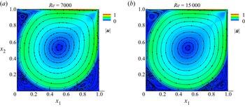
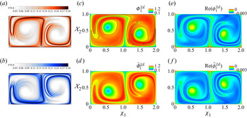
Figure 2(a) displays the steady pre-critical Reynolds number flow at  $Re_L=7000$ in terms of the absolute flow velocity
 $\boldsymbol {u}$ and select flow streamlines. Several recirculation regions are apparent: in addition to the large central feature, three smaller regions are evident near the top-left, bottom-left and bottom-right corners of the cavity. On the other hand, at the post-critical Reynolds number of
 $Re_L=15\,000$, the flow is unsteady. The pattern of figure 2(b) shows the time-averaged absolute flow velocity
 $\bar {\boldsymbol {u}}$ at
 $Re_L=15\,000$; the mean streamlines in this case indicate additional flow recirculation patterns near the lower corners. Furthermore, the skin-friction coefficient (B3) estimated along the bottom wall (figure 15b) also indicates the regions of recirculation, corresponding to the flow pattern of figure 2(b).
Flow recirculation patterns inside the lid-driven cavity at Mach number  $M_\infty =0.5$ and pre- and post-critical Reynolds numbers. (a) Steady flow velocity
 $|\boldsymbol {u}|$ at
 $Re_L=7000$ and (b) time-averaged flow velocity
 $|\bar {\boldsymbol {u}}|$ at
 $Re_L=15\,000$. Streamlines display the flow recirculation patterns.

3.3. Two-dimensional lid-driven cavity with mesh deformation
To construct a prototypical problem representing a flow with a deforming mesh, the bottom surface of the cavity is subjected to forced deformation, keeping the other flow conditions and simulation parameters the same. The deformation is governed by an analytical function expressed as
 \begin{equation} \left.\begin{array}{c} \chi_1 = x_1, \\ \chi_2(\tau)=a(1-x_2)x_1^2 (1-x_1)^2 \sin({\rm \pi} nx_1) \sin(2{\rm \pi} St_f t), \end{array}\right\} \end{equation}
where  $a$ and
 $n$ are the deformation amplitude and mode number, respectively. The non-dimensional frequency of mesh deformation is
 $St_f$. The velocity of the mesh deformation,
 $\boldsymbol {\mathcal {U}}^\texttt{G}(\boldsymbol {\mathcal {\chi }},\tau )$, is then given as
 \begin{equation} \left.\begin{array}{c} \dfrac{\partial {\chi}_1}{\partial \tau} = 0, \\ \dfrac{\partial {\chi}_2}{\partial \tau} = a(1-x_2)x_1^2(1-x_1)^2\sin({\rm \pi} nx_1)\cos(2{\rm \pi} St_f t) 2{\rm \pi} St_f. \end{array}\right\} \end{equation}
The choice of parameters,  $a=0.1$,
 $n=10$ and
 $St_f=1$, is based on obtaining a case that adequately tests the LMA development. The flow velocity in the Lagrangian (moving-mesh) frame of reference can be given by
 \begin{equation} \boldsymbol{\mathcal{U}}(\boldsymbol{\chi},\tau)= \boldsymbol{u}(\mathcal{M}(\boldsymbol{\chi},\tau))- \boldsymbol{\mathcal{U}}^\texttt{G}(\boldsymbol{\chi},\tau), \end{equation}
where  $\mathcal {M}$ is the mapping of form (2.3a,b). The flow solver accounts for the Eulerian–Lagrangian effect by enforcing the geometric conservation law (Thomas & Lombard Reference Thomas and Lombard1979; Gordnier & Visbal Reference Gordnier and Visbal2002), which governs the spatial volume element under arbitrary mapping. The deformed computational domain (
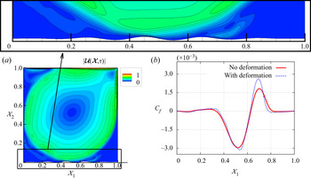
 $\texttt{G}_3$) at an arbitrary instant is shown in the inset of figure 3(a). In addition, the figure displays the absolute velocity magnitude,
 $|\boldsymbol {\mathcal {U}}(\boldsymbol {\chi },\tau )|$, on the moving mesh at that instant.
Lid-driven cavity flow at  $M_\infty =0.5$ and
 $Re_L=15\,000$ with forced bottom surface/mesh deformation. (a) Instantaneous flow velocity magnitude with contours on a deformed domain. The inset shows a closer view of the deformed domain (
 $\boldsymbol {\chi }$). (b) Skin-friction coefficient on the bottom surface with/without deformation.

The lid-driven cavity with bottom surface deflection exhibits many of the main flow features of the baseline (no boundary motion) flow including the large central region and smaller recirculation regions near the no-slip walls. The domain deformation affects the motions of these flow features, of course, particularly the smaller recirculation regions near the bottom wall. In addition to the near-wall undulations on the velocity contours in figure 3(a), the entire flow is modified to some degree due to the surface deformation. Figure 3(b) displays the skin-friction coefficient (B3) on the deforming bottom wall, indicating a discernible increase at  $\chi _1\approx 0.7$. The Lagrangian averaged flow field, estimated by accounting for the moving mesh, is largely similar to the Eulerian time-averaged flow field of figure 2(b), where the small differences can be attributed to the mild domain deformation.
3.4. Two-dimensional flow past a cylinder
The second flow considered is that past a circular cylinder, which is also a classical problem of engineering significance. The configuration highlights the fluid dynamics around bluff bodies, and encompasses many fundamental phenomena, including steady or unsteady separation, transition and wake vortex shedding (Williamson Reference Williamson1996), for all of which a large body of experimental and numerical data are available for validation. The problem is also a popular testbed for studies on flow stability, control, fluid–structure interaction, reduced-order modelling (Shinde et al. Reference Shinde, Longatte, Baj, Hoarau and Braza2016, Reference Shinde, Longatte, Baj, Hoarau and Braza2019a) and compressibility effects (Canuto & Taira Reference Canuto and Taira2015).
In this configuration, the flow transitions from steady state to unsteady vortex shedding in distinct stages. As the Reynolds number based on cylinder diameter  $D$ is increased, the initial unsteadiness is manifested for incompressible flow in
 $47 \lessapprox Re_D \lessapprox 178$ as periodic vortex shedding following a supercritical Hopf bifurcation at the critical Reynolds number (Sreenivasan, Strykowski & Olinger Reference Sreenivasan, Strykowski and Olinger1987; Noack & Eckelmann Reference Noack and Eckelmann1994). The initial two-dimensionality of the flow provides a suitable environment on which to demonstrate LMA. The onset of three-dimensionality at
 $Re_D\approx 178$, appears in the form of spanwise undulations (Behara & Mittal Reference Behara and Mittal2010).
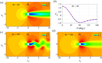
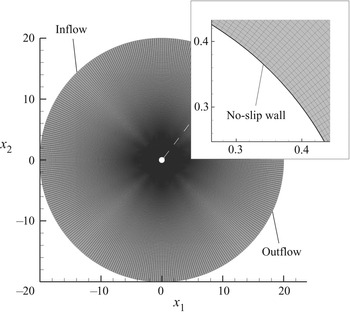
Simulations are performed for a range of Reynolds numbers  $20 \leq Re_D \leq 100$. Appendix C provides details on the geometry and grid convergence study. The flow fields are shown in figure 4 using the normalized streamwise velocity
 $u_1$ for
 $Re_D=40$ and
 $Re_D=100$. As noted earlier, the flow is steady at
 $Re_D=40$ (figure 4a). The corresponding pressure coefficient, defined as
 \begin{equation} C_p\equiv \frac{p-p_\infty}{\frac{1}{2}\rho_\infty u_\infty^2}, \end{equation}
is shown in figure 4(b) together with a favourable comparison with the DNS result of Canuto & Taira (Reference Canuto and Taira2015). For  $Re_D=100$, on the other hand, a periodic vortex shedding is observed in the wake region of the cylinder (figure 4c). The time-averaged flow field for
 $Re_D=100$ is displayed in figure 4(d). The effect of increased Reynolds number is evident when compared to the
 $Re_D=40$ flow field of figure 4(a), particularly in the wake region, which becomes more compact for
 $Re_D=100$.
Compressible flow past a cylinder, in terms of the streamwise velocity  $u_1$, at Mach number
 $M_\infty =0.5$ and Reynolds numbers
 $Re_D=40$ and
 $Re_D=100$. (a) Steady flow at
 $Re_D=40$. (b) The pressure coefficient
 $C_p$ is compared with the DNS profile of Canuto & Taira (Reference Canuto and Taira2015) (dashed line.) (c) Unsteady instantaneous flow at
 $Re_D=100$. (d) Time-mean flow at
 $Re_D=100$.

4. Results and discussion
The LMA (§ 2) is now applied to unsteady flow, without and with mesh deformation, as well as steady flow by considering the above lid-driven cavity and cylinder flows. Although the focus is on LPOD and LDMD, the general procedure is applicable to all variants of these and similar decomposition approaches. The development is performed in several steps. The unsteady lid-driven cavity flow at  $Re_L=15\,000$ is examined first, followed by an illustration on dynamic meshes with the deforming bottom surface case. Next, the techniques are applied to steady flow by considering both lid-driven cavity and cylinder cases at pre-critical Reynolds numbers of
 $Re_L=7000$ and
 $Re_D=40$, respectively. For the latter, the backward LMA, where the traces evolve in reversed time, in the Lagrangian sense, is also examined. Lastly, the LMA is used for the double-gyre flow pattern to illustrate the relation with FTLE. In all cases, the modal decompositions are performed directly on the flow fields, without subtracting the averaged flow field.
4.1. LMA on unsteady flow
As noted in § 3.2, the two-dimensional lid-driven cavity flow undergoes the first Hopf bifurcation at a critical Reynolds number in the range  $9000 \lessapprox Re_L \lessapprox 11\,000$, leading to an unsteady flow. At
 $Re_L=15\,000$, the flow undergoes successive Hopf bifurcations, exhibiting multiple frequency peaks in the power spectral density (PSD) of the flow variables. In particular, the PSD of the integrated streamwise force (
 $F_{x_1}$) on the cavity exhibits three prominent frequency peaks at Strouhal numbers
 $St_L=0.13$,
 $0.24$ and
 $0.37$. The analysis is performed using
 $2500$ solution snapshots, collected at time intervals of
 $0.01$, after the initial flow transients have disappeared from the simulation. The Eulerian results from the DNS are cast in a Lagrangian frame of reference, ensuring that the time resolution is sufficient to capture phenomena with Strouhal number in the range
 $0.04\leq St_L \leq 25$.
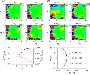
The modal decompositions provide insights into flow organization inside the cavity, which includes a primary vortex, shear regions along cavity walls and a Couette flow region near the cavity centre. These features are evident in figure 5, which displays traditional (Eulerian) POD and DMD modes using the streamwise velocity field components. The POD modes (figure 5a) are the energy-dominant flow features; the leading few modes, when ordered by energy content, comprise most of the flow energy, as shown in figure 5(c). The first POD mode is non-oscillatory (not shown) and represents the time-averaged flow field, whereas the POD modes  $\varPhi ^{u_1}_2(\boldsymbol {x})$,
 $\varPhi ^{u_1}_3(\boldsymbol {x})$,
 $\varPhi ^{u_1}_4(\boldsymbol {x})$ and
 $\varPhi ^{u_1}_5(\boldsymbol {x})$ highlight the unsteady shear regions of the lid-driven cavity. In contrast, DMD modes are distilled based on their dynamic response (frequency) and significance, which also accounts for the normalized magnitude of the mode; furthermore, as noted earlier, the DMD modes and associated Ritz values are complex. The spatial DMD modes at Strouhal numbers
 $St_L=0.13$,
 $0.24$ and
 $0.37$ are displayed in figure 5(b), while the associated Ritz values are plotted in figure 5(d).
Leading POD and DMD modes of the streamwise velocity for the lid-driven cavity at  $Re_L=15\,000$ in the Eulerian frame of reference. (a) POD modes
 $\varPhi _2^{u_1}$,
 $\varPhi _3^{u_1}$,
 $\varPhi _4^{u_1}$ and
 $\varPhi _5^{u_1}$. (b) DMD modes
 $\phi _1^{u_1}$,
 $\phi _2^{u_1}$ and
 $\phi _3^{u_1}$. (c) POD modal energies and (d) DMD eigenvalues corresponding to the spatial modes.

To perform the modal analysis in the Lagrangian frame of reference, the flow mapping of (2.3a,b) is used. A pseudocode to compute LPOD modes is provided in Appendix A. The Eulerian coordinates ( $\boldsymbol {x},t$) are transformed into the Lagrangian coordinates (
 $\boldsymbol {\chi },\tau$), starting with an identity map
 $\mathcal {M}(\boldsymbol {\chi }_0,\tau _0)$, where
 $(\boldsymbol {\chi }_0,\tau _0)=(\boldsymbol {x},t)$. The set of flow snapshots, i.e. the Eulerian flow fields
 $\boldsymbol {u}(\boldsymbol {x},t)$, along with (2.5) and (2.6) are used to construct a set of Lagrangian flow fields with respect to the identity map, i.e. simply the first Eulerian snapshot. An accurate time evolution of the flow map
 $\mathcal {M}$ from a reference state to a deformed geometric configuration requires higher-order time schemes and/or finer time steps. Alternatively, for a given set of snapshots in the Eulerian frame of reference, traditional POD can be used to reconstruct a high-time-resolved flow map. For example, the Eulerian flow fields can be reconstructed by using POD as
 \begin{equation} \boldsymbol{u}(\boldsymbol{x},t_n)=\sum_{m=1}^{N_r} \sqrt{\lambda_m}\, \boldsymbol{\varPhi}_m(\boldsymbol{x})\varPsi_m(t_n)\quad \text{for}\ n=1,2,\ldots,N_t. \end{equation}
Here  $N_t$ is the number of snapshots; and
 $N_r$ is a reduced number of POD modes used to reconstruct the flow field
 $\boldsymbol {u}$, where
 $N_r\leq N_t$.
The temporal coefficients of (4.1),  $\varPsi (t)$, can be obtained at a higher time resolution over the same time duration by performing a simple interpolation procedure, which then leads to better time resolution for the flow variable as
 \begin{equation} \tilde{\boldsymbol{u}}(\boldsymbol{x},t_n)=\sum_{m=1}^{N_r}\sqrt{\lambda_m} \,\boldsymbol{\varPhi}_m(\boldsymbol{x})\widetilde{\varPsi_m}(t_n)\quad \text{for } n=1,2,\ldots,N, \end{equation}
where  $N$, with
 $N>N_t$, is the new number of snapshots due to the time refinement. High-resolution reconstructions of the Eulerian flow field
 $\tilde {\boldsymbol {u}}(\boldsymbol {x},t)$ and (2.3a,b), (2.5) and (2.6) are used to obtain the Lagrangian flow fields to the required accuracy.
The corresponding LPOD and LDMD of the unsteady lid-driven cavity are obtained by using the same set of ( $2500$ Eulerian flow field) snapshots. As discussed above, the POD temporal coefficients are refined by a factor of
 $4$, resulting in
 $N=10\,000$ Eulerian instances. These are then transformed onto a set of
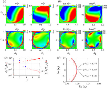
 $2500$ Lagrangian flow fields in order to perform LPOD and LDMD, by considering the first snapshot as the identity map. The prominent LPOD and LDMD modes of the Lagrangian streamwise flow velocity field are displayed in figures 6(a) and 6(b), whereas the corresponding energy contribution and frequency content are shown in figures 6(c) and 6(d), respectively. The leading LPOD modes
 $\varPhi _1^{\mathcal {U}_1}$ and
 $\varPhi _2^{\mathcal {U}_1}$ are strikingly similar to, respectively, the real and imaginary parts of the LDMD mode
 $\phi _1^{\mathcal {U}_1}$, which is associated with the Strouhal number of
 $St_L=0.125$. Furthermore, the higher LPOD modes
 $\varPhi _3^{\mathcal {U}_1}$ and
 $\varPhi _4^{\mathcal {U}_1}$ as well as the LDMD modes
 $\phi _2^{\mathcal {U}_1}$ and
 $\phi _3^{\mathcal {U}_1}$ clearly highlight the shear region of the lid-driven cavity, where the LDMD modes correspond to unsteadiness at Strouhal numbers of
 $St_L=0.267$ and
 $0.375$, respectively.
Leading LPOD and LDMD modes of the streamwise velocity for the lid-driven cavity at  $Re_L=15\,000$ in the Lagrangian frame of reference. The modes are presented using the identity map (reference grid)
 $\boldsymbol {\chi }_0(\tau _0)$ at time
 $\tau =\tau _0$. (a) LPOD modes
 $\varPhi _1^{\mathcal {U}_1}$,
 $\varPhi _2^{\mathcal {U}_1}$,
 $\varPhi _3^{\mathcal {U}_1}$ and
 $\varPhi _4^{\mathcal {U}_1}$. (b) LDMD modes
 $\phi _1^{\mathcal {U}_1}$,
 $\phi _2^{\mathcal {U}_1}$ and
 $\phi _3^{\mathcal {U}_1}$. (c) LPOD modal energies and (d) LDMD eigenvalues, indicating the values corresponding to the spatial modes.

The Lagrangian modes of figure 6 are characteristically different from the Eulerian modes of figure 5. The Couette flow and shear flow regions of the lid-driven cavity are distinctly exhibited by the Lagrangian modes; on the other hand, the Eulerian modes show modal shapes concentrated towards the bottom-left walls of the lid-driven cavity, focusing on the shear regions with a high contribution to the flow unsteadiness. In general, the decay of LPOD modal energies (figure 6c) for increasing number of modes, which is also shown in terms of cumulative modal energy, appears higher for the Eulerian set of POD modes (figure 5c). The LDMD modal patterns (figure 6b) for increasing Strouhal number are more intelligible compared to the DMD modal patterns of figure 5(b) for increasing Strouhal number.
The notion of non-uniqueness of the hyperbolic trajectories and Lyapunov exponents due to the finite time applies to the LMA ansatz as well, in the sense that the set of LMA coherent structures (e.g. LPOD/LDMD modes) changes with the identity map and time duration  $\mathcal {T}$. However, the uniqueness of the LMA modes can be ensured by considering a sufficiently long time duration and/or an appropriate flow region, where the issue naturally relates to the spatiotemporal resolution of the flow. The Ritz eigenvalues associated with DMD modes provide a measure of flow stationarity/convergence in terms of the non-growing/non-decaying global modes that lie on the unit circle. For instance, figure 6(d) displays the Ritz eigenvalues for LDMD modes of the lid-driven cavity at
 $Re_L=15\,000$, where, except for few outliers, most of the eigenvalues are along the unit circle. The corresponding Eulerian DMD eigenvalues of figure 5(d) also lie along the unit circle with some outliers. However, the eigenvalues are not perfectly on the unit circle, indicating stable (for inside the circle) and unstable (for outside the circle) tendencies of the modes. For instance, Chen, Tu & Rowley (Reference Chen, Tu and Rowley2012) and Towne et al. (Reference Towne, Schmidt and Colonius2018) discuss the equivalence between DMD and Fourier modes for zero-centred data, which ensure the zero growth/decay rate of the modes, i.e. the eigenvalues strictly lie on the unit circle. Nonetheless, LMA employs unaltered flow map data in the context of finite-time unsteady/transient dynamics, analogous to the finite-time hyperbolic trajectories and Lyapunov exponents. Notably, the Ritz values for the LDMD modes are well aligned with the unit circle (e.g. figure 6d), as opposed to the Eulerian counterpart (e.g. figure 5d).
In general, Lagrangian transport, mixing and chaos are studied using finite-time stable and unstable manifolds of hyperbolic trajectories via measures such as the FTLEs, in order to identify and monitor the transport and mixing barriers in the flow, which are the material lines and surfaces on these attracting and repelling manifolds (Branicki & Wiggins Reference Branicki and Wiggins2010; Haller Reference Haller2015; Balasuriya et al. Reference Balasuriya, Kalampattel and Ouellette2016). As noted earlier, Lyapunov exponents represent the growth of small separation between trajectories with time, leading to  $d$ number of exponents for a
 $d$-dimensional state space. A positive value of the exponent indicates an unstable trajectory, where the largest Lyapunov exponent governs the dynamics, albeit locally (Ottino Reference Ottino1989). On the other hand, the LMA ansatz acts on the entire material surface (or more generally material volume) for its global dynamics, comprising the locally stable and unstable manifolds over the considered time duration from the initial flow map. The spatiotemporal material surface/volume may exhibit linear/nonlinear, steady/unsteady and/or chaotic dynamics, dictating the transport and mixing process, whose dynamics can be conveniently examined by means of suitable LMA techniques, e.g. LPOD, LDMD and their variants.
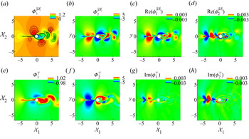
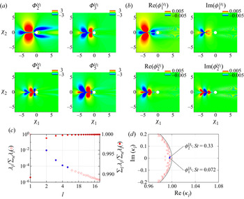
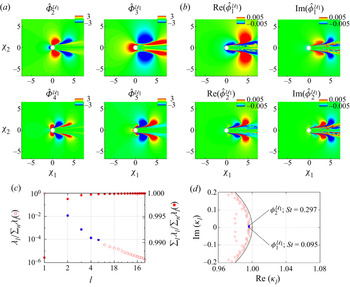
The link between the FTLE and LMA is formulated in § 2.4, elucidating the equivalence between the dominant LPOD mode of the velocity magnitude and maximum FTLE. Figure 7(a) displays the first LPOD mode of the absolute velocity for the flow past a cylinder at  $Re_D=100$ and
 $M_\infty =0.5$ (see § 3.4 and Appendix C), where the regions of high/low modal amplitudes are also delineated in terms of selected contours. This LMA analysis is performed over time
 $\tau \in [0,\mathcal {T}=5]$, utilizing
 $n=500$ material (Lagrangian) snapshots. The maximum FTLE fields at other parameters by, for example, Kasten et al. (Reference Kasten, Petz, Hotz, Noack and Hege2009) and Finn & Apte (Reference Finn and Apte2013), share several structural similarities with the LPOD mode of figure 7(a), in particular the lower-amplitude contours (on the green region) in the cylinder wake and along the upstream centreline (
 $\chi _2=0$). These regions of the flow map (material surface) are at lower absolute velocities, in the Lagrangian mean sense, over the considered finite time duration from an initial state, as opposed to the higher-amplitude regions (in red). The second LPOD mode of figure 7(b) displays the flow map regions with the largest contribution to the variance of the absolute velocity about the first LPOD mode. These flow map regions are also associated with the von Kármán vortex shedding, which becomes evident in terms of the corresponding LDMD mode with
 $St_D=0.13$ shown in figure 7(c). Clearly, the LPOD and LDMD modes of figures 7(b) and 7(c), respectively, indicate the prominent regions of the flow map exhibiting the von Kármán vortex shedding. In addition, an LDMD mode with
 $St_D=0.33$ is displayed in figure 7(d), where the flow map regions are associated with the first higher harmonic of the vortex shedding frequency (
 $St_D=0.16$). The LPOD and LDMD modes of figures 7(a)–7(d), along with the complete sets of LPOD/LDMD modes showcase spatiotemporal dynamics of the material surface, providing insights into its transport and chaotic mixing characteristics.
Leading LPOD and LDMD modes of the absolute velocity and temperature for flow past a cylinder at  $Re_D=100$ and
 $M_\infty =0.5$. The modes are displayed on the identity map (reference grid)
 $\boldsymbol {\chi }_0(\tau _0)$ at time
 $\tau =\tau _0$. (a) First LPOD mode
 $\varPhi _1^{|\boldsymbol {\mathcal {U}}|}$ and (b) second LPOD mode
 $\varPhi _2^{|\boldsymbol {\mathcal {U}}|}$ of the absolute velocity. (c) Real part of LDMD mode
 $\text {Re}(\phi _1^{|\boldsymbol {\mathcal {U}}|})$ with
 $St_D=0.13$ and (d) real part of LDMD mode
 $\text {Re}(\phi _2^{|\boldsymbol {\mathcal {U}}|})$ with
 $St_D=0.33$ for the absolute velocity. (e) First LPOD mode
 $\varPhi _1^\intercal$ and ( f) second LPOD mode
 $\varPhi _2^\intercal$ of the temperature. (g) Imaginary part of LDMD mode
 $\text {Im}(\phi _1^{\intercal })$ with
 $St_D=0.13$ and (h) imaginary part of LDMD mode
 $\text {Im}(\phi _2^{\intercal })$ with
 $St_D=0.33$ for the temperature.

In many practical situations, it is desired to obtain Lagrangian coherence of quantities other than the primary flow variables, namely, velocity, pressure and density (Balasuriya, Ouellette & Rypina Reference Balasuriya, Ouellette and Rypina2018). For example, the flow temperature, species concentration and, in general, the quantities derived from the primary variables are relevant to many multi-physics processes including, among others, turbulent combustion, acoustics and magnetohydrodynamics. In the LMA ansatz, the non-primary flow variables can also be subjected to many other modal decomposition techniques. To demonstrate this, we consider LPOD and LDMD of the temperature field that is associated with the Lagrangian flow map of the flow past a cylinder case (of § 3.4), where again the LMA analysis is performed over time  $\tau \in [0,\mathcal {T}=5]$, utilizing
 $n=500$ material (Lagrangian) snapshots. The first two LPOD modes of the temperature field (figures 7e and 7 f) exhibit coherent regions of the flow map, in terms of the Lagrangian mean and a greater part of the variance of the temperature, respectively. The LDMD modes of the temperature of figures 7(g) and 7(h) manifest the temporal dynamics of the Lagrangian thermal field with the unsteadiness of
 $St_D=0.12$ and
 $0.33$, respectively. The temperature field in the Eulerian simulation relates to the absolute velocity via the pressure and density; there is a noticeable dependence of the temperature modes on the corresponding velocity magnitude modes in figure 7.
The Lagrangian approach in fluid turbulence provides a systematic description of particles and field statistics, educing chaos and exponentially separating trajectories (Falkovich, Gawedzki & Vergassola Reference Falkovich, Gawedzki and Vergassola2001; Yeung Reference Yeung2002). In addition to remarkable physical insights into the transport, mixing and dispersion, the Lagrangian description of turbulence is useful in, for example, stochastic modelling and probability density functions (Yeung & Pope Reference Yeung and Pope1989; Pope Reference Pope1994), turbulence modelling in large-eddy simulations (Meneveau, Lund & Cabot Reference Meneveau, Lund and Cabot1996) and reduced-order modelling (Lu & Tartakovsky Reference Lu and Tartakovsky2020; Xie et al. Reference Xie, Nolan, Ross, Mou and Iliescu2020). However, such studies are limited in number compared to the Eulerian counterpart. The plethora of modal analysis techniques, in the Eulerian reference frame, inherently connect to the spatiotemporal scales of turbulence, educing coherent flow structures, where these prominent flow features are utilized in, among others, flow control and optimization, reduced-order modelling and turbulence modelling (Rowley & Dawson Reference Rowley and Dawson2017; Shinde Reference Shinde2020). Thus, the LMA provides a means to transform the Eulerian modal analysis techniques and their applications to the Lagrangian flow maps (material surfaces/volumes).
4.2. LMA on flow with mesh deformation
The difficulties of applying modal decompositions to deforming meshes and associated domains in the Eulerian frame are overcome by recasting such problems in the Lagrangian formulation. The LMA on the flow with deforming meshes can be performed at least in two settings: in the first case, the (material) flow map is considered to be the frame of reference, whereas in the second case the moving/deforming mesh is taken as the frame of reference. In either case, the modal analysis is not restricted because of the moving/deforming domain. Here we demonstrate the second possibility of performing LMA, where the Lagrangian frame of reference is the deforming mesh. Two major advantages of this approach are: (i) the flow fields for the LMA, in general, already account for the deforming mesh in the Eulerian–Lagrangian computations; and (ii) the LMA distils out modes that are associated with the mesh deformation from the modes of the flow fields, as illustrated below.
The two-dimensional lid-driven cavity with mesh deformation (see § 3.3) is considered. As detailed in § 3.3, the bottom wall of the lid-driven cavity is subjected to forced sinusoidal deformation ( 3.10 and 3.11) at a Strouhal number  $St_L=1$, which affects the mesh in the entire domain. The resulting flow fields are always unsteady at all Reynolds numbers due to the time-dependent domain deformation. As before,
 $2500$ snapshots are collected at time intervals of
 $0.01$, encompassing Strouhal numbers in the range
 $0.04\leq St \leq 25$. The first Eulerian snapshot is considered as the identity map for the Lagrangian transformation of (2.3a,b), where the Lagrangian coordinates
 $(\boldsymbol {\chi }_0,\tau _0)=(\boldsymbol {x},t)$.
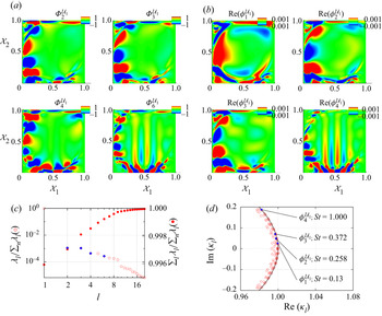
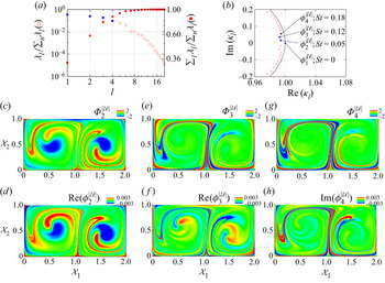
The leading LPOD and LDMD modes of the streamwise flow velocity are displayed in figure 8 together with their energy and frequency content data, respectively. Figures 8(a) and 8(b) use the Eulerian/Lagrangian coordinates at the reference state (identity map). The leading spatial LPOD and LDMD modes of figure 8 closely resemble the Eulerian POD and DMD modes of figure 5, in terms of the spatial structure, modal energy and frequency content. This is consistent with the findings of Menon & Mittal (Reference Menon and Mittal2020), where the DMD modes at frequencies other than the rigid-body motion were shown to be unmodified. However, the spatial modes of figure 8 display differences compared to those of figure 5, mainly in regions of large mesh deformation, i.e. near the bottom wall of the lid-driven cavity. These differences between the Eulerian and Lagrangian modes are congruent with those between the corresponding flow fields of figures 2 and 3, respectively.
Leading LPOD and LDMD modes of the streamwise velocity for the lid-driven cavity at  $Re_L=15\,000$ subjected to forced bottom surface deformation at
 $St_L=1.0$. The modes are presented using the identity map (reference grid)
 $\boldsymbol {\chi }_0(\tau _0)$ at time
 $\tau =\tau _0$. (a) LPOD modes
 $\varPhi _2^{\mathcal {U}_1}$,
 $\varPhi _3^{\mathcal {U}_1}$,
 $\varPhi _4^{\mathcal {U}_1}$ and
 $\varPhi _6^{\mathcal {U}_1}$. (b) LDMD modes
 $\phi _1^{\mathcal {U}_1}$,
 $\phi _2^{\mathcal {U}_1}$,
 $\phi _3^{\mathcal {U}_1}$ and
 $\phi _4^{\mathcal {U}_1}$. (c) LPOD modal energies and (d) LDMD eigenvalues, indicating the values corresponding to the spatial modes.

Furthermore, figures 8(a) and 8(b) include an LPOD and LDMD mode, respectively, which correspond to the forced mesh deformation, where the LDMD mode ( $\phi _4^{\mathcal {U}_1}$) exhibits a modal frequency equal to the forcing frequency of
 $St=1$. The Lagrangian modes that correspond to the domain deformation,
 $\varPhi _6^{\mathcal {U}_1}$ (LPOD) and
 $\text {Re}(\phi _4^{\mathcal {U}_1})$ (LDMD), precisely indicate the regions of the flow that are affected by the bottom surface deflection. This is of significant practical importance for the flow control using surface morphing (Bruce & Colliss Reference Bruce and Colliss2015; Shinde, McNamara & Gaitonde Reference Shinde, McNamara and Gaitonde2020; Shinde, Gaitonde & McNamara Reference Shinde, Gaitonde and McNamara2021), where the effect of control surface deformation on the flow fields can be identified using LMA for the efficacy of control.
4.3. LMA on steady flows
In the Eulerian description, a steady flow is characterized by time-independent flow variables. From the stability point of view, a base flow or fixed point is a flow state where all the solutions to an initial value problem converge monotonically. The stability properties of the flow can be characterized based on the temporal/spatial evolution of the external perturbations superimposed on the steady base flow state. In addition to stability analysis, the steady base flow can be subjected to different analyses that are of practical interest, such as, for instance, resolvent analysis (Sharma & McKeon Reference Sharma and McKeon2013; Schmid & Brandt Reference Schmid and Brandt2014). A steady non-uniform flow in the Eulerian frame of reference transforms to an unsteady flow in the Lagrangian frame of reference, enabling the use of Lagrangian modal decompositions (of § 2) directly for the steady flows. The Eulerian steady base flow/fixed point again serves as the identity map of (2.3a,b) for the Lagrangian flow diffeomorphism. A set of flow snapshots may be extracted from the phase portrait of the base flow, starting at the identity map and tracing the diffeomorphism of the Lagrangian domain for increasing time. Alternatively, the time direction may be reversed by tracing the diffeomorphism of the Lagrangian domain in the negative (backward) time direction. The forward and adjoint (backward) formulations to perform the Lagrangian modal analysis of a steady base flow are discussed in this section.
4.3.1. Forward Lagrangian approach
The lid-driven cavity flow at the pre-critical Reynolds number of  $Re_L=7000$ (see § 3.2, figure 2a) is considered here for the Lagrangian modal analysis. The steady base flow in the Eulerian frame of reference is then represented in the Lagrangian frame of reference according to (2.3a,b), (2.5) and (2.6). The Lagrangian flow map is allowed to evolve in the positive/forward time direction from the reference steady state by solving an initial value problem. A set of
 $2500$ snapshots of the Lagrangian flow fields at time interval of
 $0.01$ are collected to perform the modal analysis, while a much smaller time step of
 $\delta t = 0.001$ is used to accurately track the Lagrangian flow map.
The leading LPOD and LDMD modes of the streamwise flow velocity for the steady lid-driven cavity at  $Re_L=7000$ are displayed in figures 9(a) and 9(b), while the corresponding modal energies of LPOD and modal frequencies of LDMD modes are shown in figures 9(c) and 9(d), respectively. The energy-dominant LPOD modes
 $\varPhi _1^{\mathcal {U}_1}$ and
 $\varPhi _2^{\mathcal {U}_1}$ are nearly identical to the real and imaginary components of the LDMD mode
 $\phi _1^{\mathcal {U}_1}$, respectively. Notably, although the flow is steady in the Eulerian sense, the LDMD mode
 $\phi _1^{\mathcal {U}_1}$ corresponds to the unsteadiness of
 $St_L=0.133$, as shown in figure 9(d). Furthermore, the LDMD modes
 $\phi _2^{\mathcal {U}_1}$ and
 $\phi _3^{\mathcal {U}_1}$ of figure 9(b) are associated with the Strouhal numbers
 $St_L=0.28$ and
 $0.41$, respectively, from the Lagrangian point of view. The LPOD modes
 $\varPhi _5^{\mathcal {U}_1}$ and
 $\varPhi _7^{\mathcal {U}_1}$ (of figure 9a) correspond to the LDMD modes
 $\phi _2^{\mathcal {U}_1}$ and
 $\phi _3^{\mathcal {U}_1}$, respectively.
Leading modes of the steady-state streamwise flow velocity for the lid-driven cavity at  $Re_L=7000$ in the Lagrangian frame of reference. (a) LPOD modes
 $\varPhi _1^{\mathcal {U}_1}$,
 $\varPhi _2^{\mathcal {U}_1}$,
 $\varPhi _8^{\mathcal {U}_1}$ and
 $\varPhi _{17}^{\mathcal {U}_1}$. (b) LDMD modes
 $\phi _1^{\mathcal {U}_1}$,
 $\phi _2^{\mathcal {U}_1}$ and
 $\phi _3^{\mathcal {U}_1}$. (c) LPOD modal energies and (d) LDMD eigenvalues, indicating the values corresponding to the spatial modes.

As discussed in § 3.2, the lid-driven cavity flow becomes unstable beyond the critical Reynolds number of  $Re_c \approx 10\,500$; furthermore, at the post-critical Reynolds number of
 $Re_L=15\,000$, the flow exhibits dominant frequency peaks at
 $St_L=0.13$,
 $0.25$ and
 $0.39$. For the steady lid-driven cavity flow at
 $Re_L=7000$, the LDMD modes at these frequencies closely resemble the LDMD modes at
 $Re_L=15\,000$ (figure 6b), which also represent energetically significant LPOD modes. Importantly, the Lagrangian approach of modal decomposition provides a means to extract the dynamically significant flow features that are embedded in the steady base flow. This feature of LMA is of significant importance from the base flow stability point of view.
The Eulerian to Lagrangian flow mapping of (2.3a,b) for the flow past a cylinder (of § 3.4) needs a special treatment due to the convective/open nature of the flow; this is different from the lid-driven cavity flow (of § 3.2), where the diffeomorphism  $\textit {SDiff}(\mathcal {D})$ is always confined to the original Eulerian flow domain
 $\mathsf { {D}}$. The time evolution of the diffeomorphism
 $\textit {SDiff}(\mathcal {D})$ for the flow past a cylinder is not confined to the original Eulerian flow domain
 $\mathsf { {D}}$ or the flow domain
 $\mathcal {D}$ of the identity map
 $\mathcal {M}(\boldsymbol {\chi }_0,\tau _0)$. Note that this applies to the unsteady lid-driven cavity and cylinder flows discussed in § 4.1. A simple remedy to this problem is to use the (Eulerian) flow conditions at the outlet boundary for the (Lagrangian) flow that has left the computational domain, and considering the diffeomorphism for a limited time for a meaningful analysis.
The LMA is also performed for the steady flow past a cylinder at  $Re_D=40$. The steady base flow serves as the reference state for the Lagrangian mapping of (2.3a,b), while (2.5) and (2.6) are used to extract the time-dependent Lagrangian flow fields. Some
 $1000$ snapshots are collected at time intervals of
 $0.005$, and the Lagrangian flow map is again obtained at a much smaller time step of
 $\delta t=0.001$ for accuracy. Thus, the finite-time duration for the LMA is
 $\tau \in [0,\mathcal {T}=5]$, the same as for the LMA on unsteady flow past a cylinder at
 $Re_D=100$ discussed before in § 4.1. The significant LPOD and LDMD modes of the streamwise flow velocity are depicted in figures 10(a) and 10(b) with their energy and frequency content in figures 10(c) and 10(d), respectively. Figure 10(b) displays the real and imaginary parts of the LDMD modes
 $\phi _1^{\mathcal {U}_1}$ and
 $\phi _2^{\mathcal {U}_1}$ that exhibit Strouhal numbers of
 $St_D=0.072$ and
 $0.33$, respectively. The LPOD mode
 $\varPhi _2^{\mathcal {U}_1}$ resembles the LDMD mode
 $\phi _2^{\mathcal {U}_1}$, which is associated with the Strouhal number of
 $0.072$; furthermore, the higher LPOD modes (
 $\varPhi _3^{\mathcal {U}_1}$,
 $\varPhi _4^{\mathcal {U}_1}$ and
 $\varPhi _5^{\mathcal {U}_1}$), in general, show the structural similarity with the LDMD modes.
Leading modes of the steady-state streamwise flow velocity for the flow past a cylinder at  $Re_D=40$ in the Lagrangian frame of reference. (a) LPOD modes
 $\varPhi _2^{\mathcal {U}_1}$,
 $\varPhi _3^{\mathcal {U}_1}$,
 $\varPhi _4^{\mathcal {U}_1}$ and
 $\varPhi _5^{\mathcal {U}_1}$. (b) LDMD modes
 $\phi _1^{\mathcal {U}_1}$ and
 $\phi _2^{\mathcal {U}_1}$. (c) LPOD modal energies and (d) LDMD eigenvalues, indicating the values corresponding to the spatial modes.

The two-dimensional flow past a cylinder in the post-critical regime ( $50 \lessapprox Re_D \lessapprox 190$) exhibits a distinct unsteadiness at a Strouhal number of
 $St_D=0.16$, which is associated with the shedding of vortices in the wake region (refer to § 3.4). The LDMD modes
 $\phi _1^{\mathcal {U}_1}$ and
 $\phi _2^{\mathcal {U}_1}$ exhibit Strouhal numbers of
 $St_D=0.072$ and
 $0.33$, while the LDMD modes of the flow normal velocity component
 $\phi _1^{\mathcal {U}_2}$ and
 $\phi _2^{\mathcal {U}_2}$ (not shown) exhibit Strouhal numbers of
 $St_D=0.06$ and
 $0.18$. The LPOD mode
 $\varPhi _2^{\mathcal {U}_1}$ of figure 10(a) and LDMD mode
 $\text {Re}(\phi _2^{\mathcal {U}_1})$ of figure 10(a) exhibit structural similarities with the LPOD mode of figure 7(b) and LDMD mode of figure 7(d), respectively, particularly in the upstream region of the cylinder. Note that the steady case (
 $Re_D=40$; figure 10) displays LMA of the streamwise velocity, whereas the unsteady case (
 $Re_D=100$; figure 7) displays LMA of the absolute velocity. Nonetheless, the breakdown of the modal symmetry about
 $\chi _2=0$ for increased Reynolds number is evident, particularly in the wake region, clearly manifesting the unsteady effects of the von Kármán shedding in terms of the considered flow maps (material surfaces). Importantly, the LMA of the steady base flow can extract flow features that, in general, correspond to the unsteady flow dynamics from the post-bifurcation regime.
The LPOD and LDMD modes (of figures 10a and 10b, respectively) are displayed on the reference flow state or identity map, which is the initial condition for the Lagrangian flow map. Interestingly, the LPOD and LDMD modes indicate upstream regions of the cylinder that correspond to the unsteady flow dynamics associated with the downstream/wake region of the cylinder. In other words, the procedure tracks the Lagrangian flow map in the future time/space and then traces back the flow variations to the identity map in terms of the modal decomposition. Alternatively, the analysis can be performed by reversing the time direction, in which the Lagrangian flow map is traced in prior time/space and the flow variations can then be tracked forward to the identity map. The latter approach is referred to as the adjoint Lagrangian approach of modal decomposition, which we discuss in the following section (§ 4.3.2).
4.3.2. Adjoint Lagrangian approach
Adjoint-based analyses find utility in the study of flow receptivity, sensitivity and stability; in addition, these procedures are employed in design and optimization (Hill Reference Hill1995; Schmid Reference Schmid2007; Browne et al. Reference Browne, Rubio, Ferrer and Valero2014; Iorio, González & Ferrer Reference Iorio, González and Ferrer2014; Luchini & Bottaro Reference Luchini and Bottaro2014). Briefly, the adjoint equations of a linear or nonlinear system of equations are effectively solved by reversing the direction of time (Chandler et al. Reference Chandler, Juniper, Nichols and Schmid2012). In the similar manner, the Lagrangian flow map of (2.3a,b) can be obtained for negative direction of time  $t$ as
 \begin{align} \left. \begin{array}{c@{}} \mathcal{M}:\mathcal{D}\times [0,\mathcal{T}] \rightarrow \textit{SDiff}(\mathcal{D})\subseteq \mathsf{\textit{E}}=\mathbb{R}^3: (\boldsymbol{\chi},\tau) \mapsto \mathcal{M}(\boldsymbol{\chi},\tau)=(\boldsymbol{x},-t) \\ \text{and} \qquad \mathcal{M}(\boldsymbol{\chi}_0,\tau_0)=\text{ identity map} \end{array}\right\}, \end{align}
where the identity map is now the terminal condition, from the Eulerian point of view. In addition, (2.5) and (2.6) also consider the negative time direction, while the Eulerian flow fields are transformed to the Lagrangian flow fields.
In matrix form, let  $\boldsymbol { {\mathsf {X}}}\in \mathbb {R}^{m\times n}$ and
 $\boldsymbol { {\mathsf {Y}}}\in \mathbb {R}^{m\times n}$ be the discrete sets of Lagrangian flow fields that are gathered in the forward and backward time directions. The real symmetric tensors
 $\boldsymbol { {\mathsf {X}}}^\textrm {T} \boldsymbol { {\mathsf {X}}}$ and
 $\boldsymbol { {\mathsf {Y}}}^\textrm {T}\boldsymbol { {\mathsf {Y}}}$ are self-adjoint by definition. For reversed initial and terminal conditions, the corresponding eigenvalue problems for the two tensors result in an identical set of orthonormal eigenfunctions (
 $\boldsymbol {\varPhi }$) and real eigenvalues (
 $\boldsymbol {\varLambda }$), indicating that the two symmetric tensors are adjoint and normal (Chandler et al. Reference Chandler, Juniper, Nichols and Schmid2012). Following the LPOD/LDMD framework (of § 2), the matrices can be expressed as
 \begin{equation} \boldsymbol{{\mathsf{X}}}=\boldsymbol{\varPhi}\boldsymbol{\varLambda}^{{1}/{2}} \boldsymbol{\varPsi}_{{x}}^\textrm{T} \quad \text{and} \quad \boldsymbol{{\mathsf{Y}}}=\boldsymbol{\varPhi}\boldsymbol{\varLambda}^{{1}/{2}} \boldsymbol{\varPsi}_{{y}}^\textrm{T}, \end{equation}
which leads to
 \begin{equation} \boldsymbol{{\mathsf{X}}}\boldsymbol{\varPsi}_{{x}}= \boldsymbol{{\mathsf{Y}}}\boldsymbol{\varPsi}_{{y}}, \end{equation}
satisfying an adjoint formalism
 \begin{equation} \boldsymbol{{\mathsf{X}}}= \boldsymbol{{\mathsf{Y}}}\boldsymbol{\varPsi}_{y} \boldsymbol{\varPsi}_{x}^\textrm{T} \quad \text{and} \quad \boldsymbol{{\mathsf{Y}}}= \boldsymbol{{\mathsf{X}}}\boldsymbol{\varPsi}_{x} \boldsymbol{\varPsi}_{y}^\textrm{T}, \end{equation}
with an adjoint operator  $(\boldsymbol {\varPsi }_{y}\boldsymbol {\varPsi }_{x}^\textrm {T}) \in \mathbb {R}^{n\times n}$. However, for the same initial condition (or the identity map), the data matrices
 $\boldsymbol { {\mathsf {X}}}$ and
 $\boldsymbol { {\mathsf {Y}}}$ may not lead to exactly the same set of eigenfunctions and eigenvalues due to the non-normality of the flow fields with advection (Chomaz Reference Chomaz2005; Marquet et al. Reference Marquet, Lombardi, Chomaz, Sipp and Jacquin2009); on the other hand, the forward and backward data matrices can lead to normal operators depending on flow symmetries, for instance those in the absolutely unstable flows (Symon et al. Reference Symon, Rosenberg, Dawson and McKeon2018).
To compute the backward/adjoint modes, similar to the forward Lagrangian modal decomposition of the flow past a cylinder in § 4.3.1,  $1000$ snapshots are collected at time intervals of
 $0.01$, i.e.
 $-0.01$ from the Eulerian point of view, while the Lagrangian flow map evolves with a finer time step of
 $\delta t =0.001$ for accuracy. The leading adjoint LPOD and LDMD modes of the streamwise flow velocity are shown in figures 11(a) and 11(b) together with their energy and frequency content in figures 11(c) and 11(d), respectively. As opposed to the forward Lagrangian modes of figures 10(a) and 10(b), the adjoint modes appear in the downstream region of the flow. These modes indicate synchronized regions of the flow (i.e. the streamwise velocity), which were subjected to similar variations of the magnitude and wavelength over the considered time in the past. Like for the forward Lagrangian modes (of figure 10), the adjoint modes are symmetric about the
 $\chi _2=0$ line, mainly indicating the shear layer regions of the flow. Notably, similar to the forward LDMD, the adjoint LDMD modes
 $\hat {\phi }_1^{\mathcal {U}_1}$ and
 $\hat {\phi }_2^{\mathcal {U}_1}$ of figure 11(b) exhibit unsteadiness at Strouhal numbers of
 $St_D=0.095$ and
 $0.297$, respectively, relevant to the post-bifurcation dynamics.
Leading adjoint modes of the steady-state streamwise flow velocity for the flow past a cylinder at  $Re_D=40$ in the Lagrangian frame of reference. (a) Adjoint LPOD modes
 $\hat {\varPhi }_2^{\mathcal {U}_1}$,
 $\hat {\varPhi }_3^{\mathcal {U}_1}$,
 $\hat {\varPhi }_4^{\mathcal {U}_1}$ and
 $\hat {\varPhi }_5^{\mathcal {U}_1}$. (b) Adjoint LDMD modes
 $\hat {\phi }_1^{\mathcal {U}_1}$ and
 $\hat {\phi }_2^{\mathcal {U}_1}$. (c) Adjoint LPOD modal energies and (d) adjoint LDMD eigenvalues, indicating frequencies associated with the spatial modes.

4.4. Double-gyre flow
As noted earlier, the (maximum) FTLE is extensively used in understanding the flow chaos, mixing and transport, which play an important role in the geophysical flows (d'Ovidio et al. Reference d'Ovidio, Fernández, Hernández-García and López2004; Allshouse & Peacock Reference Allshouse and Peacock2015; BozorgMagham & Ross Reference BozorgMagham and Ross2015; Garaboa-Paz et al. Reference Garaboa-Paz, Eiras-Barca, Huhn and Pérez-Muñuzuri2015); in addition, the FTLE finds application in biological (Green, Rowley & Smits Reference Green, Rowley and Smits2010; Shadden & Arzani Reference Shadden and Arzani2015) and several industrial (González et al. Reference González, Speth, Gaitonde and Lewis2016; Dauch et al. Reference Dauch, Ates, Rapp, Keller, Chaussonnet, Kaden, Okraschevski, Koch, Dachsbacher and Bauer2019) flows. To elaborate on the relation between the FTLE and LMA, we consider a double-gyre flow pattern of interest in geophysical flows. As presented by Shadden et al. (Reference Shadden, Lekien and Marsden2005), a simple potential flow leads to an oscillating double-gyre flow pattern for a non-zero perturbation parameter, exhibiting an engagement between the classical stable/unstable manifolds (Rom-Kedar, Leonard & Wiggins Reference Rom-Kedar, Leonard and Wiggins1990; Guckenheimer & Holmes Reference Guckenheimer and Holmes2013).
The periodically varying double-gyre flow is described by a streamfunction, in the Eulerian frame of reference, as
 \begin{equation} \psi(x_1,x_2,t) = {a} \sin({\rm \pi} f(x_1,t)) \sin({\rm \pi} x_2), \end{equation}
where
 $$\begin{gather} f(x_1,t) = a(t) x_1^2 + b(t) x_1 , \end{gather}$$
 $$\begin{gather}a(t) = \epsilon \sin(2{\rm \pi} St_f t) , \end{gather}$$
 $$\begin{gather}b(t) = 1 - 2\epsilon \sin(2{\rm \pi} St_f t) , \end{gather}$$
over a domain  $\mathsf { {D}} \times [0,\mathsf { {T}}]$ such that
 $x_1 \in [0,2]$,
 $x_2\in [0,1]$ and
 $t\in [0,15]$. This simple mathematical model produces two counter-rotating flow cells. A non-zero value of the parameter
 $\epsilon$ leads to the time-dependent double-gyre flow (Shadden et al. Reference Shadden, Lekien and Marsden2005). The two components of the velocity field are
 $$\begin{gather} u_1 ={-}\frac{\partial \psi}{\partial x_2} ={-}{\rm \pi} {a} \sin({\rm \pi} f(x_1,t)) \cos({\rm \pi} x_2), \end{gather}$$
 $$\begin{gather}u_2 = \frac{\partial \psi}{\partial x_1} = {\rm \pi}{a} \cos({\rm \pi} f(x_1,t)) \frac{\textrm{d} \,f(x_1,t)}{\textrm{d}\kern0.7pt x_1} \sin({\rm \pi} x_2). \end{gather}$$
The parameter  ${a}$ determines the magnitude of velocity, while
 $St$ is the Strouhal number associated with the flow unsteadiness. The Eulerian flow fields are generated for
 ${a}=0.1$,
 $St=0.1$ and
 $\epsilon =0.1$ over the computational domain discretized by
 $n_{x_1}\times n_{x_2} = 601 \times 301$ grid points, while the time-step value of
 $\delta t=0.05$ results in a total number of
 $301$ snapshots.
The FTLE fields for the double-gyre flow in the forward and backward time flow maps are as shown in figures 12(a) and 12(b), respectively, which are reproduced here from Finn & Apte (Reference Finn and Apte2013). To perform the Lagrangian modal analysis of this flow, the Eulerian snapshots are transformed to a Lagrangian frame of reference. The LPOD and LDMD modes are then obtained for both forward and backward Lagrangian flow maps. The first LPOD and adjoint LPOD modes, which correspond to the maximum eigenvalues, are displayed in figures 12(c) and 12(d), respectively, while the LDMD and adjoint LDMD modes that are stationary (in the finite-time Lagrangian sense;  $St=0$) are shown in figures 12(e) and 12( f), respectively. The FTLE field, which highlights the maximum eigenvalues of the right Cauchy–Green strain tensor, is expected to be geometrically similar to the first LPOD mode (see § 2.4), which corresponds to the largest eigenvalue. The resemblance between the first LPOD modes (figures 12c and 12d) and the FTLE fields (figures 12a and 12b) is evident in figure 12, in both the forward and backward time directions. In the finite-time Lagrangian sense, the first LPOD modes correspond to the mean field of the absolute velocity, while the corresponding LDMD modes display no associated unsteadiness (
 $St=0$), as shown in figures 12(e) and 12( f). The LDMD and adjoint LDMD modes closely match the LPOD and adjoint LPOD modes, exhibiting geometrical similarities with the forward and backward FTLE fields, respectively.
Comparison between the FTLE, LPOD and LDMD modes of the double-gyre flow. (a) Forward FTLE and (b) backward FTLE reference data from Finn & Apte (Reference Finn and Apte2013). The first (c) forward ( ${\varPhi }_1^{|\boldsymbol {\mathcal {U}}|}$, with a single contour level of value
 $1$) and (d) adjoint (
 $\hat {\varPhi }_1^{|\boldsymbol {\mathcal {U}}|}$) LPOD modes, as well as the only stationary (e) forward (
 ${\phi }_1^{|\boldsymbol {\mathcal {U}}|}$) and ( f) adjoint (
 $\hat {\phi }_1^{|\boldsymbol {\mathcal {U}}|}$) LDMD modes for the double-gyre flow.

The simple double-gyre flow leads to a single significant (in terms of the modal energy) LPOD mode, while the higher LPOD modes comprise relatively lower modal energy, as shown in figure 13(a). For instance, the relative energy of the second LPOD mode is  $\lambda _2^{|\boldsymbol {\mathcal {U}}|}/\lambda _1^{|\boldsymbol {\mathcal {U}}|} \approx 0.01$, which decreases further for the higher-rank LPOD modes. The Ritz spectrum of eigenvalues for the LDMD modes is displayed in figure 13(b). The stationary mode corresponds to
 $St=0$; in addition, the LDMD modes that have higher modal weights and frequencies of
 $St=0.05$,
 $0.11$ and
 $0.18$ are marked in figure 13(b). The spatial structures of the higher-rank LPOD and LDMD modes, displayed in figures 13(c)–13(h), exhibit higher modal values (contributions) along the peak values of FTLE field (also FTLE ridges) of figure 12(a), indicating the spatiotemporal dynamics.
Modal energies/frequencies and higher-rank Lagrangian POD/DMD modes of the double-gyre flow. (a) LPOD modal energies, (b) LDMD eigenvalues and modal frequencies, (c) LPOD mode  $\varPhi _2^{|\boldsymbol {\mathcal {U}}|}$, (d) LPOD mode
 $\varPhi _3^{|\boldsymbol {\mathcal {U}}|}$, (e) LPOD mode
 $\varPhi _4^{|\boldsymbol {\mathcal {U}}|}$, ( f) real part of LDMD mode
 $\phi _2^{|\boldsymbol {\mathcal {U}}|}$, (g) real part of LDMD mode
 $\phi _3^{|\boldsymbol {\mathcal {U}}|}$, and (h) imaginary part of LDMD mode
 $\phi _4^{|\boldsymbol {\mathcal {U}}|}$.

The first LPOD mode of figure 12(c) also displays a single contour level at an arbitrary value of  $\varPhi _1^{|\boldsymbol {\mathcal {U}}|}=1$, delineating the lower velocity magnitude regions of the flow map (material surface) of the double-gyre flow. Clearly, the peak values of the FTLE field are encompassed in the
 $\varPhi _1^{|\boldsymbol {\mathcal {U}}|} \lessapprox 1$ region of the first LPOD mode (similarly the
 $\text {Re}(\phi _1^{|\boldsymbol {\mathcal {U}}|}) \gtrapprox -0.002$ region of the LDMD mode). In addition to the high stretching regions of the flow map, the contour level
 $\varPhi _1^{|\boldsymbol {\mathcal {U}}|} = 1$ of the LPOD mode outlines the two core regions of the double-gyre flow. The dynamics of the two gyre cores, in the finite-time sense, is apparent by LDMD mode
 $\text {Re}(\phi _2^{|\boldsymbol {\mathcal {U}}|})$ with
 $St=0.05$ in figure 13(d), which also corresponds to the second most energetic LPOD mode (figure 13a). The LMA, in general, manifests the spatiotemporal coherence between the different regions of the flow map, where identification of these Lagrangian flow patterns are of paramount significance in the geophysical, chemical and biological flows, among others.
5. Conclusion
Modal analyses of fluid flows, such as popular POD and DMD, are typically performed in an Eulerian (fixed) frame of reference, leading to time-invariant spatial modes. These techniques, however, face difficulties when the numerical simulations and experiments comprise deforming/moving domains, such as in fluid–structure interaction problems. To address this issue, we have presented a Lagrangian approach of modal analysis of fluid flows, where the Eulerian flow fields are a posteriori transformed to Lagrangian (deforming/moving) flow fields. For deforming/moving domains, the Lagrangian modal analysis can be alternatively performed in the Lagrangian (material) flow map or moving-mesh frame of reference. Interestingly, in the latter case, the LMA distils out modes that are associated with the domain deformation; in addition, the Lagrangian modes exhibit a large structural similarity with the Eulerian modes on the otherwise static domain. The LMA (e.g. LPOD/LDMD) procedures elegantly manage the deforming/moving domain, enabling modal analysis with reference to the identity map, which is the initial Lagrangian flow map.
In the material frame of reference, the spatiotemporal material surface/volume is subjected to the LMA. The Lagrangian (material) flow map is useful in many circumstances; it is central to turbulent mixing and transport (Ottino Reference Ottino1989; Wiggins Reference Wiggins2005), where features such as fixed points, periodic orbits, stable and unstable manifolds and chaotic attractors become manifest (Shadden et al. Reference Shadden, Lekien and Marsden2005; Haller Reference Haller2015). In general, most Lagrangian techniques developed to analyse the dynamics of Lagrangian flow map (material surface/volume) naturally relate to or build upon the FTLE, elucidating finite-time dynamics of the material trajectories. The LMA brings forth a Lagrangian framework for modal decomposition of a spatiotemporal material flow map, providing valuable insights into prominent Lagrangian coherent flow structures and associated dynamics pertinent to the decomposition technique. For instance, the first LPOD mode is shown to relate closely with the maximum FTLE field, while the higher LPOD modes represent energetically coherent structures of the material flow map; on the other hand, LDMD modes represent dynamically coherent structures of the Lagrangian flow map, exhibiting energy amplification and resonance behaviour (Schmid Reference Schmid2010) of not only the primitive variables but also the derived/passive variables, e.g. vorticity, species concentration and temperature.
The Eulerian POD and DMD find restricted usage on steady/base/turbulent mean flows (Schmid Reference Schmid2010; Shinde et al. Reference Shinde, McNamara, Gaitonde, Barnes and Visbal2019b), which are time-independent, whereas the Lagrangian POD and DMD can be directly employed for non-uniform steady/base/turbulent mean flows, which are inevitably unsteady in the Lagrangian frame of reference. The LMA on (Eulerian) steady flow yields Lagrangian coherent flow structures that continue to exist in the post-critical (post-bifurcation) flow regime, exhibiting prominent LPOD/LDMD modes that are likely to be engaged in flow transition. For instance, the LPOD/LDMD modes of the lid-driven cavity at  $Re_L=7000$ (pre-bifurcation; figure 9) and
 $Re_L=15\,000$ (post-bifurcation; figure 6) are strikingly similar, providing insights into the prominent Lagrangian flow features, including those associated with the post-bifurcation unsteadiness.
The notions of finite-time analysis and time duality pertain to the LMA ansatz, analogous to hyperbolic trajectories and FTLE. The forward and adjoint LMA analysis yields Lagrangian (LPOD/LDMD) modes in the upstream and downstream regions of flow, respectively, which potentially leads to flow sensitivity, receptivity and controllability. In addition, the LMA remains to be explored for applications that include other features such as barriers in the turbulent mixing and transport, stability characteristics of the steady/base/turbulent mean flows, flow control and optimization in terms of the adjoint formulation, and turbulence and reduced-order modelling.
Funding
We acknowledge support from the Collaborative Center for Aeronautical Sciences sponsored by the Air Force Research Laboratory.
Declaration of interests
The authors report no conflict of interest.
Appendix A. Pseudo-algorithm and source code to perform Lagrangian modal analysis
In this section, we present a procedure to perform Lagrangian modal analysis in terms of the Lagrangian POD, considering the simple double-gyre flow configuration of § 4.4. The pseudo-algorithm of table 1 describes the steps necessary to compute LPOD modes. Briefly, the input to the algorithm is a set of Eulerian flow fields and associated flow parameters that include the grid, the solution state variables, the number of snapshots ( $N_t$) and the time step (
 $\delta t$). A negative value of the time step is used to perform backward Lagrangian modal analysis, resulting in the adjoint LPOD modes. The initial Eulerian flow state
 $\boldsymbol {u} (\boldsymbol {x}_0,t_0)$ represents the identity map for the Lagrangian flow map, thus
 $\boldsymbol {\mathcal {U}}(\boldsymbol {\chi }_0,\tau _0) =\boldsymbol {u}(\boldsymbol {x}_0,t_0)$. An equal number of Lagrangian snapshots (
 $N_t$) are obtained for the forward (
 $\delta \tau =\delta t$) or backward (
 $\delta \tau =-\delta t$) passage of time. The Lagrangian snapshots can also be extracted from a single snapshot of a steady Eulerian base flow, in both the forward and backward directions. Lastly, the POD is performed on the Lagrangian flow fields, by computing the correlation matrix via an appropriate weight matrix and solving the eigenvalue problem.
Pseudo-algorithm for computing Lagrangian POD modes using a set of Eulerian snapshots.

The source code of the algorithm (table 1) is available in fortran 90 at GitHub link to LagrangianModalAnalysis. In addition to the Lagrangian modal analysis sources, the repository includes a subroutine that generates the double-gyre flow snapshots in the Eulerian frame of reference.
Appendix B. Grid convergence of the lid-driven cavity
The geometrical configuration of the lid-driven cavity is displayed in figure 14. The size of the square cavity is  $L_{ref}=L$, and the side and bottom surfaces (edges) are prescribed with the no-slip wall and adiabatic boundary conditions. A uniform velocity
 $u_1=u_\infty$ in the
 $x_1$ direction is assigned to the top surface, which also uses a Dirichlet condition for all the reference variables. The specification of regularized velocity profile at the top surface (Shen Reference Shen1991) is not considered, since the effects are not significant (Bergamo et al. Reference Bergamo, Gennaro, Theofilis and Medeiros2015) for the current purposes.
Computational domain of the two-dimensional lid-driven cavity. The inset displays a small region of mesh  $\texttt{M}_{\texttt{2}}$ with uniform discretization in either direction.

The computational domain is uniformly discretized in either direction, as shown in the inset of figure 14. A mesh sensitivity study is performed for  $Re_L=15\,000$ with four meshes, designated
 $\texttt{G}_{\texttt{1}}$,
 $\texttt{G}_{\texttt{3}}$,
 $\texttt{G}_{\texttt{3}}$ and
 $\texttt{G}_{\texttt{4}}$. The drag and lift coefficients are
 \begin{equation} C_d\equiv\frac{F_{x_1}}{\frac{1}{2}\rho_\infty u_\infty^2 L} \quad \text{and} \quad C_l\equiv\frac{F_{x_2}}{\frac{1}{2}\rho_\infty u_\infty^2 L}, \end{equation}
where  $F_{x_1}$ and
 $F_{x_2}$ are the forces on the no-slip walls in the
 $x_1$ and
 $x_2$ directions, respectively, and are noted in table 2, where the overline (
 $\overline {\,\cdot \,}$) and
 $rms$ denote the standard time-averaging and root-mean-square of fluctuations operations, respectively. These parameters display relatively mesh-independent results on
 $\texttt{G}_{\texttt{3}}$ and
 $\texttt{G}_{\texttt{4}}$. In addition, table 2 displays the Strouhal number,
 \begin{equation} St_L\equiv\frac{fL}{u_\infty}, \end{equation}
where the flow frequency  $f$ and its higher harmonics are estimated using the PSD of the integrated force
 $F_{x_1}$ on the cavity. The Strouhal numbers exhibit converged values for the grids
 $\texttt{G}_3$ and
 $\texttt{G}_4$, similar to the convergence of the drag and lift coefficients.
Mesh details for the lid-driven cavity at the Reynolds number  $Re_L=15\,000$ and Mach number
 $M_\infty =0.5$, mesh sensitivity of the time-averaged and root-mean-squared (
 $rms$) drag and lift coefficients, and the Strouhal number with its higher harmonics.

Flow velocity components and the skin-friction coefficient, in the time-mean sense, are displayed in figures 15(a) and 15(b), respectively, for all meshes. The time-averaged velocity components  $\bar {u}_1$ and
 $\bar {u}_2$ along the vertical (
 $x_1=0.5$) and horizontal (
 $x_2=0.5$) centrelines, respectively, are nearly identical with respect to meshes
 $\texttt{G}_2$,
 $\texttt{G}_3$ and
 $\texttt{G}_4$. On the other hand, the skin-friction coefficient on the bottom wall of the cavity, which is defined as
 \begin{equation} C_f=\frac{\bar{\sigma}_{12}|_{x_2=0}}{\frac{1}{2}\rho_\infty u_\infty^2}, \end{equation}
exhibits some dependence on the mesh refinement from  $\texttt{G}_1$ to
 $\texttt{G}_2$, albeit rather locally. The overall results appear grid-converged for meshes
 $\texttt{G}_3$ and
 $\texttt{G}_4$; thus mesh
 $\texttt{G}_3$ is considered for the results and discussion.
Grid convergence of the results for the lid-driven cavity at  $Re_L=15\,000$. (a) Time-averaged flow velocity components along the cavity centrelines and (b) the skin-friction coefficient on the bottom wall of the cavity for the four grids
 $\texttt{G}_1$,
 $\texttt{G}_2$,
 $\texttt{G}_3$ and
 $\texttt{G}_4$.

Appendix C. Grid convergence of the flow past a cylinder
The DNS database of flow past a cylinder is constructed at a Mach number  $M_\infty =0.5$, for which unsteadiness appears at
 $Re_D\approx 50$. Two Reynolds numbers, namely
 $Re_D=40$ and
 $100$, are chosen to yield pre-bifurcation and post-bifurcation solutions, respectively. The former condition results in a steady separated flow, while the latter manifests two-dimensional unsteady vortex shedding. The computational domain, displayed in figure 16, is discretized with a structured cylindrical mesh. The cylinder is placed at the origin, with outer boundaries
 $40D$ away. The inflow is uniform with a normalized velocity
 $u_\infty =1.0$, while the outflow is obtained by extrapolation of all variables except pressure, which is maintained constant at
 $p_\infty =1/\gamma M_\infty ^2$ in the far field. The cylinder surface (perimeter) is prescribed with a no-slip wall and adiabatic boundary conditions. Periodicity is enforced in the azimuthal direction.
Computational domain with mesh  $\texttt{M}_1$ to simulate flow past a cylinder of diameter
 $D$. The outer boundary is placed at
 $40D$ from the centre. The inset shows the near-wall mesh structure.

The sensitivity of the results to spatial resolution is examined using two meshes,  $\texttt{M}_1$ and
 $\texttt{M}_2$, whose details and effect on the results are provided in table 3. In mesh
 $\texttt{M}_1$, the cylinder surface (perimeter) is discretized using
 $n_\theta =361$ grid points. In the radial direction, the first grid point is placed at
 ${\rm \pi} D/2(n_\theta -1)$, while the radial extent is divided into
 $n_r=n_\theta$ points by using a geometric progression with a growth ratio of
 $r=1.0103$. For mesh
 $\texttt{M}_2$,
 $n_\theta =541$ is used, resulting in the radial growth ratio of
 $1.0069$.
Details of the computational meshes  $\texttt{M}_1$ and
 $\texttt{M}_2$, mesh sensitivity to drag and lift coefficients and Strouhal number for
 $Re_D=100$ and
 $M_\infty =0.5$ for the flow past a cylinder.

The drag and lift coefficients are defined as
 \begin{equation} C_d\equiv \frac{F_d}{\frac{1}{2}\rho_\infty u_\infty^2 D} \quad \text{and} \quad C_l\equiv \frac{F_l}{\frac{1}{2}\rho_\infty u_\infty^2 D}, \end{equation}
where  $F_d$ and
 $F_l$ are the forces in the
 $x$ and
 $y$ directions, respectively. The frequency of unsteady vortex shedding is reported using the Strouhal number,
 \begin{equation} St_D\equiv \frac{fD}{u_\infty}. \end{equation}
The drag ( $C_d$) and lift (
 $C_l$) coefficients change little between the two meshes; in addition, the Strouhal number computed using
 $C_l$ is nearly identical for the two meshes. The results also match well with the literature (Canuto & Taira Reference Canuto and Taira2015). Thus, we consider the mesh
 $\texttt{M}_1$ for further analysis.