


Introduction
Continuously measuring inclinometers embedded in glacier ice allow us to monitor the tilt and azimuth angles of the axis of the instrument with high temporal resolution (Reference Gudmundsson, Bauder, Lüthi, Fischer and FunkGudmundsson and others, 1999; Reference Pfeffer, Humphrey, Amadei, Harper and WegmannPfeffer and others, 2000; Reference Marshall, Harper, Pfeffer and HumphreyMarshall and others, 2002; Reference Amundson, Truffer and LüthiAmundson and others, 2006). The instruments constitute a solid body of given geometry floating in a comparably soft viscous fluid. Due to the different properties of the probe and the fluid, the local strain field is perturbed by the probe. It is thus not obvious how the local strain rates in the ice are reflected in the rotation axis and rate of the instrument.
An inclinometer that is fully equipped for, for example, two-axis gravity sensors and three-axis magnetometers is in principle suited to measure the absolute orientation of a rigid tripod attached to the instrument with respect to a given coordinate system (Fig. 1). Thus, we can monitor the rotation in space (e.g. through the changes in the tilt or zenith angle and the azimuth of the long axis of the inclinometer, and the rotation angle about this axis).
Geometrical set-up of an inclinometer. The orientation in space of the tripod of vectors e 1, e 2 and e 3 fixed to the instrument is given with respect to a coordinate system x 1, x 2 and x 3. The angles θ and ϕ are the zenith and azimuth angles of the long axis, and γ is the rotation angle about this axis.

The spatial rotation of the probe is a result of the geometry of the instrument and of the deformation field of the ice. The forward problem is the computation of the rotation vector of the instrument for a given deformation field, either the strain rate or velocity gradient components, which is given by a Stokes problem for given boundary conditions. The inverse problem requires the determination of the deformation field from given rotation vectors of the instrument, which is not straightforward.
It seems reasonable to assume that a spherical body reflects the local rigid rotation of the ice motion. A very thin linear probe is assumed to behave like a Lagrangian unit vector (Reference Keller and BlatterKeller and Blatter, 2012), a vector rigidly attached to an infinitesimal piece of the ice and moving with this ice. In this paper, we examine the validity of the latter assumption, which we call the unit vector model. To this purpose, we compare numerical model results of an extremely viscous rectangular body, representing a solid, floating in a deforming fluid, to the unit vector model.
We restrict our analysis to two dimensions defined by the local horizontal flow direction, x 1, and the direction opposite to gravity, x 3. Only normal strain and pure horizontal shear are assumed, as in Reference Keller and BlatterKeller and Blatter (2012). The probe is assumed to be small enough such that macroscopic inhomogeneities (e.g. in the fields of temperature and strain rate) are not significant, and large enough that microscopic inhomogeneities (e.g. ice crystals) do not play a role. The coupling of the instruments to the ice seems to be difficult in temperate ice (Reference Pfeffer, Humphrey, Amadei, Harper and WegmannPfeffer and others, 2000; Reference Keller and BlatterKeller and Blatter, 2012). Therefore, we consider only the well-defined cold case with no slip on the surface of the probe. Furthermore, buoyancy is neglected.
Unit Vector Model
The rectangular inclinometer always starts from a position with a vertical long axis, i.e. with a zenith angle θ 0 = 0. With this assumption, equations (15) and (16) of Reference Keller and BlatterKeller and Blatter (2012) reduce to

where θ(t) is the zenith angle of the instrument axis as a function of time and L 13 and L 33 are components of the velocity gradient tensor, Lij = ∂ui/∂xj . The time derivative of Eqn (1) at t = 0 yields
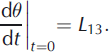
Thus, at the starting point with θ(0) = 0, the influence of L 33 vanishes and the rotation rate of the unit vector, Eqn (2), reflects only the rotation part of the velocity field. For t → ∞ the angle θ approaches a limit angle

with L 33 t > 0; for L 33 t < 0, the limit angle is π/2. The limit angles are determined by the directions of the principal strain-rate components.
Numerical Model
The model solves a Stokes problem for a square domain including a rectangular or circular domain representing the solid floating in the fluid (Fig. 2). On the boundary between the solid and fluid bodies, continuity of the velocity and stress fields is imposed. The viscosity of the solid is chosen seven orders of magnitude larger than that of the fluid representing the ice. The conditions on the boundary of the square are chosen as
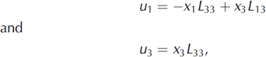
such that the field of strain rate within the domain is homogeneous with given values for L 13 and L 33 and the drifting velocity in the center of the domain vanishes, if the solid body is not included. The square domain Ω2 is centered at the origin. For reasons of symmetry, the rectangular probe rotates about the origin and is always started from an upright position, θ 0 = 0.
Computation domain with the two fluid domains Ω1(t) and Ω2(t) and the level set function φ(x, t). θ(t) is the zenith angle of the long axis of the inclinometer.

We consider Ω ⊂ R 2, a square domain filled with two Newtonian or Glen-type non-Newtonian immiscible and incompressible fluids. At time t, the two fluids occupy the domains Ω1(t) and Ω2(t) (Fig. 2) which are defined by a continuous level set function φ,

Given the fluid velocity u, the level set function φ must satisfy the advection equation

so the contour line φ = 0 (level set) always follows the boundary between Ω1(t) and Ω2(t).
Neglecting inertial terms, the mass and momentum conservation equations are


where p is the pressure, g is the acceleration of gravity and the superscript T denotes the transpose of the velocity gradient tensor Δu. The density ρ and the viscosity η are defined by

where ρi and ηi are the densities and viscosities in the corresponding domains Ω i . Note that Eqns (7) and (8) are understood in the weak sense, thus assuming the continuity of forces and velocity at the interface between the two fluids. To approximate the rigid body motion, Δu + Δu T = 0 in Ω1, we can set η 1 to a very large value.
Let Δt be the time-step, for each i > 0: given φi , an approximation of φ(ti ), we compute ρi and ηi using Eqn (9) and search ui +1, pi +1 at time ti +1 = ti + Δt such that

The Stokes problem is solved using finite elements with linear polynomials to approximate the pressure, and quadratic polynomials to approximate the velocity. Given a velocity ui +1, the new level set ϕi +1 is computed by solving Eqn (6) between ti and ti +1 with the so-called method of characteristics (see, e.g., Reference PironneauPironneau, 1989). The model is implemented using the FreeFem++ software for solving partial differential equations (http://www.freefem.org/). Extensive tests of the accuracy and convergence of the model are presented in Reference JaberJaber (2012).
Numerical Experiments
Equation (1) can be considered to be a function of two dimensionless variables, L 13 /L 33 and dimensionless time t L 33. To generate the flow field in the interior of the domain, correspondingly, a dimensionless Stokes equation is solved. Only the ratios between the strain-rate components, and thus also between the stress components, are relevant. Consequently, the choice of the dimensionless constant viscosity is also free. In the presented results we chose the viscosity of the fluid η = 10 and the viscosity of the solid probe η 1 = 108, which makes its deformation rate small enough to make the probe almost rigid for the time-span of the model experiments. In all experiments, the model domain is a square with a side length 2, the structured mesh size is 0.01 and the time-step is Δt = 0.0028.
Aspect of probe: Newtonian fluid
In this experiment, we consider L 13/L 33 = 1/3. The width of the rectangles is chosen 0.1 and the lengths vary from 0.2 to 0.4. The evolution of the tilt angle θ(t) for the different aspect ratios, length to width, of the probe is plotted in Figure 3, together with the unit vector solution according to Eqn (1). Rectangles with aspect ratios larger than 4 are closely approximated by the behavior of a unit vector with a comparable limit tilt angle. Conversely, for aspect ratios close to and below 2, the rectangles continue to rotate. The same discrimination applies to the starting rotation rate. The initial rotation rate L13 of the Lagrangian unit vector is close to the modeled rotation rate for large enough aspect ratios (>4) but overestimates it for smaller aspect ratios.
The evolution of the tilt angle θ for a Newtonian fluid with L
13 = L
33 = 1/3 as a function of dimensionless time  for rectangular shapes with different aspect ratios: 2, 3 and 3.5 for the indicated dashed lines, 4 for the dotted line almost hidden in the solid line for the unit vector model.

Newtonian and Glen-type fluids
The local perturbation of the flow field and thus the strain-rate components of a given probe also changes the viscosity of a non-Newtonian fluid. We implemented the viscosity according to the modified Glen’s flow law (Reference Greve and BlatterGreve and Blatter, 2009),

where d e is the second invariant of the strain-rate tensor, n = 3 is the flow law exponent, A is a rate factor and the residual stress σ o is a small positive constant acting as a regularization parameter. With the chosen values of A = 0.08 and σ o = 0.3, the viscosity in the unperturbed region corresponds to the viscosity in the Newtonian fluid solutions. The viscosity is updated every time-step using a fixed point iteration scheme.
Due to its symmetry, a circular probe only sees the rotation part of the velocity field, and thus rotates with an angular velocity ω = ∂θ/∂t = L 13. A square probe is expected to rotate continuously, without stabilizing in a tilt position. Figure 4 shows the time evolution of an axis fixed to a circle with diameter 0.1 and to a square with side 0.1. Due to its symmetry, a circle must rotate uniformly with rotation rate L 13 in a Newtonian fluid, which is confirmed in the numerical simulation. Contrary to this, the square rotates slightly slower in the tilt position compared to the upright position.
The evolution of the tilt angle θ as a function of dimensionless time  for a circular and a square shape for Newtonian and Glen-type fluids for L
13 = L
33 = 1/3: the dashed lines show the the results for a Newtonian fluid, the solid lines for a Glen-type fluid, the corresponding upper lines for the square, the corresponding lower lines for circles. The upper dashed line also corresponds to a rotation with angular velocity
 .

The rotation rates of square and circular bodies are consistently smaller in a Glen-type fluid than in a Newtonian fluid with constant viscosity (Fig. 4). The no-slip condition on the surface of the body drags the fluid with the surface, so the shear rate is smaller closer to the body than anywhere further away, in particular along the sides of the square. This increased drag seems to slow down the rotation in the Glen-type fluid.
Figure 5 shows an example of the evolution of the zenith angle for a rectangular probe with aspect ratio 4 for an asymptotic strain field of L 13/L 33 = 1 for both Newtonian and Glen-type fluids. For this aspect ratio, the unit vector model closely matches the rotation of the rectangle for the Newtonian fluid. For the transient phase, the unit vector model overestimates the rotation rate of the rectangle in the Glen-type fluid, and thus underestimates L 13. Furthermore, the zenith angle converges towards a smaller limit angle than the unit vector, and thus underestimates the ratio L 13/L 33· The directions of the principal strain-rate components of the perturbed strain fields are different for Newtonian and Glen-type fluids.
The evolution of the angle θ as a function of dimensionless time  for a rectangle with aspect ratio 4 for a Newtonian (dashed line) and a Glen-type (solid line) fluid with L
13 = L
33 = 0.4. The upper line for the linear fluid also matches the unit vector model.

Conclusions and Discussion
The assumption that an inclinometer probe embedded in glacier ice behaves like a Lagrangian unit vector (Reference Keller and BlatterKeller and Blatter, 2012) is tested with a Stokes model of the motion of a rectangular solid (very viscous) body floating in a fluid, with both Newtonian and Glen-type rheology. The assumption turned out to be viable only for Newtonian fluids and if the length-to-width ratio of the probe exceeds ∼4. At the start of the rotation with an upright long axis, the rotation rate is slightly smaller for smaller aspect ratios of the rectangle but approaches the rotation rate of the unit vector solution for large enough aspect ratios. The limit angle decreases with increasing aspect ratio and also approaches the limit angle of the unit vector solution for large enough aspect ratios. For smaller aspect ratios, the shear strain L 13 is overestimated at the start with θ = 0, and the ratio L 13/L 33 from the limit angle is underestimated with the unit vector solution (Fig. 3). A modified Glen-type fluid yields smaller rotation rates compared to the Newtonian fluid and a smaller limit angle. Thus, the unit vector solution consistently overestimates L 13 and L 13/L 33.
We cannot exclude a significant influence on the rotation rate due to the three-dimensional shape of the probe and the attached cable, especially if the probe is shorter than the recommended four times the width. To avoid such complication it may be advisable to use a freely floating wireless probe as developed recently (Reference Hart, Martinez, Ong, Riddoch, Rose and PadhyHart and others, 2006; Reference SmeetsSmeets and others, 2012). An embedded inclinometer thus is not a trivial instrument for the measurement of strain rates in glaciers. This was demonstrated for the application of the unit vector model in Reference Keller and BlatterKeller and Blatter (2012) and is demonstrated in the experiments presented here, and may be even more critical if the strain field is truly three-dimensional. This may require additional numerical modeling not only of the behavior of a given inclinometer in the local strain field, but also a modeling of the larger-scale strain field in the glacier to plan field experiments and to constrain the interpretation of the inclinometer readings.
Acknowledgements
We thank Sérgio H. Faria, W. Tad Pfeffer and Erik Blake for constructive reviews and their help in substantially improving the manuscript.



