1 Introduction
When a drop impacts on a pool, it produces the well-known Edgerton crown (Edgerton & Killian Reference Edgerton and Killian1939). This iconic bowl-like structure usually breaks up through a capillary-driven edge instability (Yarin & Weiss Reference Yarin and Weiss1995; Deegan, Brunet & Eggers Reference Deegan, Brunet and Eggers2008). Rein (Reference Rein1993) included a review of the earliest work on this phenomenon, whereas Roisman, Horvat & Tropea (Reference Roisman, Horvat and Tropea2006) and Yarin (Reference Yarin2006) looked at more recent theoretical and experimental studies. Yarin & Weiss (Reference Yarin and Weiss1995) developed a quasi-one dimensional analytic model for crown evolution, describing it as a kinematic discontinuity. The crown breakup was explained by the instabilities of the liquid rim of the crown due to cusp formation. Wang & Chen (Reference Wang and Chen2000) found that the crown wall is almost perpendicular to the horizontal liquid film, as suggested in the review by Rein (Reference Rein1993). Trujillo & Lee (Reference Trujillo and Lee2001) extended their work to include the influence of viscous losses, concluding that the influence of viscosity was not significant for very large Reynolds numbers. Roisman & Tropea (Reference Roisman and Tropea2002) extended these theories for the generalized case where the crown can emerge at an angle to the vertical. They formulated a prediction for the angle between the drop and thin film, in the vein of Peregrine (Reference Peregrine1981). This angle prediction includes the velocity and the film thickness inside the crown, which are difficult to measure accurately. Fedorchenko & Wang (Reference Fedorchenko and Wang2004) produced a simplified version where the angle increases monotonically with the substrate-film thickness
 $\unicode[STIX]{x1D6FF}$
, which can be compared to our measurements in the thin-film regime, where its thickness is within a quarter of the drop size, i.e.
 $\unicode[STIX]{x1D6FF}/D<0.25$
. Weiss & Yarin (Reference Weiss and Yarin1999) and Thoroddsen (Reference Thoroddsen2002) discovered the horizontal ejecta sheet which emerges from the neck between the drop and pool and precedes the crown.
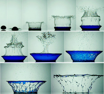
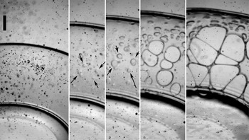
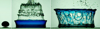
The impact of a glycerine drop which has been coloured with methylene-blue dye, onto a thin substrate film of isopropanol (IPA), with
 $\unicode[STIX]{x1D6FF}^{\ast }=\unicode[STIX]{x1D6FF}/D_{H}=0.052$
. The ejected sheet of the film liquid has risen above the drop where it buckles and ruptures into a multitude of fine spray droplets, which rain down on the blue crown, to promote the formation of the Marangoni holes. This occurs without any crown-edge instability. Frames are shown at
 $t=-0.03$
, 0.10, 0.60, 1.17, 2.00, 2.87, 4.77, 7.40, 9.60 and 16.8 ms from first contact.
 $D_{H}=5.00~\text{mm}$
and
 $U=8.13~\text{m}~\text{s}^{-1}$
.
 $Re_{d}=43$
,
 $We_{f}=11\,300$
. See also supplementary movie 1 available at https://doi.org/10.1017/jfm.2018.178.

Very few studies have looked at configurations where the drop and the pool consist of different liquids. Thoroddsen, Etoh & Takehara (Reference Thoroddsen, Etoh and Takehara2006a ,Reference Thoroddsen, Etoh and Takehara b ) showed that the breakup of the crown can occur through Marangoni-driven holes. For example, when the pool is of a liquid with lower surface tension than the drop, they proposed that spray droplets from the ejecta can hit the crown, thereby producing divergent free-surface stress, which leads to holes forming in the thin crown-sheet, as is shown in figure 1. Such breakup is of practical significance in a number of applications (Geppert et al. Reference Geppert, Chatzianagnostou, Meister, Gomaa, Lamanna and Weigand2016).
Kittel, Roisman & Tropea (Reference Kittel, Roisman and Tropea2016) used water and silicone oils to vary the viscosity between that of the pool and that of the drop, by over two orders of magnitude, while their impact velocity was kept fixed at
 $3.2~\text{m}~\text{s}^{-1}$
thereby giving Reynolds numbers based on film properties
 $Re_{film}\leqslant 6000$
, which is much lower than that studied herein. They do not observe any spray sheet or Marangoni holes. Banks, Ajawara & Aguilar (Reference Banks, Ajawara and Aguilar2012) also varied the viscosity of drop versus film.
Herein, we aim to pin down the role of the fine spray in the hole formation, by directly imaging the interaction of the fine droplets with the crown wall. We will also study the effects of changing the properties of the drop and film liquids. Specifically we focus on changing the surface tensions and viscosities of the two.
2 Experimental set-up
2.1 Impact conditions
This study looks at the impact of a high-viscosity drop onto a thin film of a lower-viscosity liquid. Experiments were all conducted for a similar impact velocity, but over a range of drop viscosities and varying the thin-film composition and thicknesses
 $\unicode[STIX]{x1D6FF}$
on the glass substrate. The release height of the drop was kept constant at
 $H\simeq 5.4$
m, which leads to impact velocities
 $U$
between
 $8.1~\text{m}~\text{s}^{-1}$
and
 $8.6~\text{m}~\text{s}^{-1}$
, depending on the size of the drop and the corresponding influence of air drag. For each configuration
 $U$
is measured directly from the video clips. The first frame in figure 1 shows typical drop shapes at impact. The drops are significantly flattened by the air resistance. The highly viscous drops consist of silicone oils, or glycerine/water mixtures of 94 %–100 % by weight of glycerine. This generated drops with dynamic viscosities
 $\unicode[STIX]{x1D707}$
in the range from 500 cP to 1250 cP. A limited set of experiments was performed for lower drop viscosities of 5 cP and 50 cP, but these do not lead to the regular crowns studied herein.
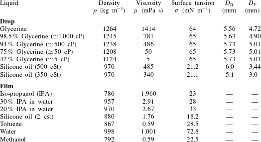
The drops are generated by pinch off from a plastic nozzle having inner diameter of 4.2 mm. The liquid is fed from a glass separator funnel with a gate valve to control the flow rate. The resulting drop sizes vary for the different liquid viscosities and surface tensions, as listed in table 1. Then, the drops fall through a 5 m long Plexiglas pipe to minimize the sideways drift of the drop during the free fall, due to unavoidable air currents in the laboratory. The substrate was a glass plate of size
 $50~\text{mm}\times 75$
mm and 1 mm thick. All experiments were conducted at room temperature of
 $21\,^{\circ }\text{C}$
.
In a limited set of experiments we dissolved methylene-blue powdered dye into the water/glycerine drop liquid, to allow us to distinguish drop and pool liquids during the impact. This lowered slightly the drop viscosity and surface tension, by less than 7 % and 4 % respectively, as measured in house. This does not change significantly the overall crown evolution, while it may affect the details of the ruptures. Therefore, the Marangoni holes were only studied for drops which did not contain this dye.
Liquid properties.

2.2 The thin film and
 $\unicode[STIX]{x0394}\unicode[STIX]{x1D70E}$

The viscosity of the film is always much lower than that of the drop. This effectively changes the boundary condition under the high-viscosity drop from no slip on the solid, to partial slip, allowing it to deform into an extended sheet which rises above the substrate to form the crown. By using different liquids in the film, such as isopropanol (IPA), silicone oils, toluene or IPA/water mixtures, we can systematically change its surface tension relative to that of the drop. The film layer was generated by depositing a small measured amount of the liquid on the glass. To generate repeatable film thicknesses
 $\unicode[STIX]{x1D6FF}$
, a fixed procedure was followed every time. A fixed amount of the film liquid was fed from a syringe onto the centre of the glass plate which it wets. It takes approximately 50 s to spread into a uniform film covering the entire plate. The time between liquid deposition to drop impact was kept constant to reduce variability in the amount of evaporation, which reduces the film thickness. Furthermore, the substrate was replaced with a new clean one after each impact. This eliminates possibility of contamination of the film liquid from earlier drops.
The amount of evaporation was measured by placing the spreading film and the substrate on a sensitive balance. The film thickness was corrected for this evaporated amount at the time of impact.
We systematically change the thickness of the film to study its effect on the shape of the drop crown and ejected spray sheet. The amount of deposited liquid varied between 0.25 ml and 2 ml, giving
 $\unicode[STIX]{x1D6FF}\simeq 0.065$
, 0.125, 0.195, 0.265, 0.39 and 0.53 mm. Our film thicknesses are therefore always in the thin-film regime, defined by Fedorchenko & Wang (Reference Fedorchenko and Wang2004)
 $$\begin{eqnarray}\unicode[STIX]{x1D6FF}^{\ast }=\unicode[STIX]{x1D6FF}/D_{H}<0.25,\end{eqnarray}$$
where we normalize the thickness by the horizontal diameter
 $D_{H}$
of the drop at impact. For our data
 $\unicode[STIX]{x1D6FF}^{\ast }<0.11$
.
The driving force for the hole formation is the difference in surface tension between the drop and the pool liquid. We have systematically changed
 $\unicode[STIX]{x0394}\unicode[STIX]{x1D70E}=(\unicode[STIX]{x1D70E}_{drop}-\unicode[STIX]{x1D70E}_{film})$
, from
 $-8~\text{mN}~\text{m}^{-1}$
to
 $41~\text{mN}~\text{m}^{-1}$
, by using the various different liquids in the drop and film, as listed in table 1.
2.3 High-speed imaging
The impacts were imaged using a long distance microscope, with adjustable magnification (Leica APO-16), mostly with a
 $1\times$
interchangeable objective. This gives a pixel resolution of
 ${\sim}40~\unicode[STIX]{x03BC}\text{m}~\text{px}^{-1}$
. The breakup of the droplet requires high-speed video at a frame rate of up to 80 kfps, which were acquired with Phantom V2511 or Phantom V711 (colour) video cameras. Most video sequences used side view, with others taken from an oblique view at
 $45^{\circ }$
, at larger magnification of
 ${\sim}30~\unicode[STIX]{x03BC}\text{m}~\text{px}^{-1}$
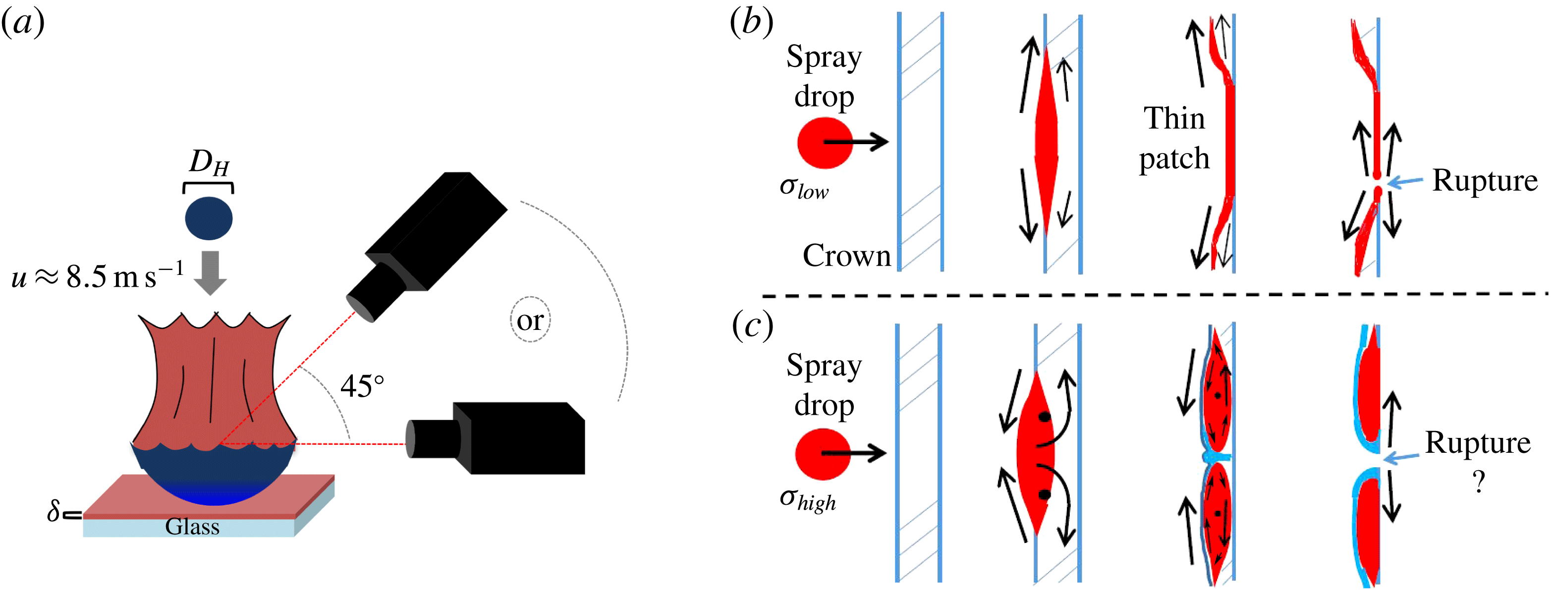
. Back lighting used a 350 W metal-halide lamp (Sumita), shone onto a diffuser sheet. However, the largest magnifications and highest frame rates required direct lighting, without a diffuser. This experimental configuration is sketched in figure 2(a).
(a) Experimental set-up, with camera viewing angles. The liquid film, of thickness
 $\unicode[STIX]{x1D6FF}$
, is deposited onto a microscope slide. (b) Sketch of the proposed hole-formation mechanisms when spray
 $\unicode[STIX]{x1D70E}$
is smaller or larger (c) than that of the liquid forming the drop crown.

2.4 Range of parameters
The impacts are characterized by Weber and Reynolds numbers, which are based on the horizontal diameter of the drop
 $D_{H}$
and the impact velocity
 $U$
. The liquid properties can however be based on the viscosity and surface tension either of the drop liquid, or of the thin film. Based on the film or drop properties these numbers are mostly in the ranges
 $$\begin{eqnarray}We_{f}=\frac{\unicode[STIX]{x1D70C}_{f}D_{H}U^{2}}{\unicode[STIX]{x1D70E}_{f}}=8480{-}19\,000;\quad We_{d}=\frac{\unicode[STIX]{x1D70C}_{d}D_{H}U^{2}}{\unicode[STIX]{x1D70E}_{d}}=8250{-}21\,000;\end{eqnarray}$$
 $$\begin{eqnarray}Re_{f}=\frac{D_{H}U}{\unicode[STIX]{x1D708}_{f}}=19\,800{-}65\,600;\quad Re_{d}=\frac{D_{H}U}{\unicode[STIX]{x1D708}_{d}}=44{-}128.\end{eqnarray}$$
These values might indicate that the dynamics of the film on the substrate is governed by inertia, whereas
 $\unicode[STIX]{x1D70E}_{f}$
and
 $\unicode[STIX]{x1D707}_{f}$
play minimal roles. However, the ejecta sheets, emerging from the film, become exceedingly thin and their motions are greatly affected by air resistance and surface tension (Thoroddsen et al.
Reference Thoroddsen, Thoraval, Takehara and Etoh2011; Marston et al.
Reference Marston, Truscott, Speirs, Mansoor and Thoroddsen2016). This is especially true when the sheets rupture and the typical spray droplet sizes become
 $1~\unicode[STIX]{x03BC}\text{m}$
–
 $100~\unicode[STIX]{x03BC}\text{m}$
. On the other hand, the overall drop crown is formed in an interplay of inertia and the drop viscosity
 $\unicode[STIX]{x1D707}_{d}$
, with little influence from
 $\unicode[STIX]{x1D70E}_{d}$
until the ruptures form.
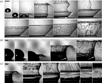
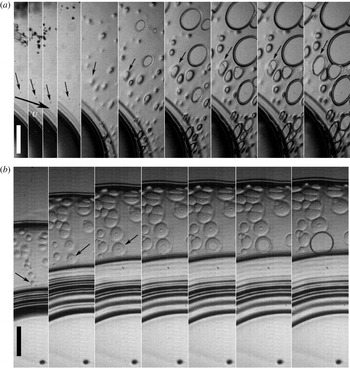
Impact of a glycerine drop on an IPA film of thickness
 $\unicode[STIX]{x1D6FF}^{\ast }=\unicode[STIX]{x1D6FF}/D_{H}=0.052$
. (a) The arrows indicate the principal directions of strain of the crown sheet. Note how the crown wall is smooth until the IPA sheet has ruptured with spray hitting the inside of the crown wall in the second row of frames. Times shown are
 $t=-0.5$
, 0, 0.23, 1.07, 2.03, 3.90, 5.0, 6.4, 7.7, 10.5 ms. The scale bar is 5 mm long. (b) Close up of the spray formation for the same conditions as in (a). The first frames show the origin of the ejecta sheet, which quickly breaks up into horizontally moving fine spray, before the continuous spray sheet extends vertically. The arrows indicate the emergence of the top of the drop crown. Times shown are
 $t=16$
, 32, 128, 400 and
 $576~\unicode[STIX]{x03BC}\text{s}$
after first contact. (c) The appearance of the microdroplets moving down within the crown, marked by the arrows. For
 $t=0.34$
, 1.35, 1.88, 2.65, 4.12 and 5.26 ms. Note that the crown wall is smooth before the arrival of the microdroplets. The scale bars in (b,c) are 1 mm long.

3 Results
3.1 Overall crown evolution and spray trajectories
Figure 1 shows a typical example of the crown breakup mechanism. Immediately following the impact of the drop, a horizontal ejecta sheet emerges from the film liquid, as studied by Thoroddsen (Reference Thoroddsen2002). This sheet is visible in the second image of figure 1. The tip of this sheet quickly breaks up into fine spray, which travels away from the impact (see also figure 3 b for close up images). The base of this fine ejecta sheet connects to the tip of the emerging crown of drop liquid. We have coloured the drop with methylene-blue dye, to show clearly where the drop liquid has formed the crown and thus verify that the thin uncoloured clear sheet above it must have originated from the film on the substrate. This was also verified using a different dye (fluorescein) by Thoroddsen et al. (Reference Thoroddsen, Etoh and Takehara2006a ). The isopropanol film rises far above the drop crown and is pulled towards the centreline by the air flow (sketched in figure 4b), producing the intricate buckled patterns. Once this sheet ruptures, the air flow and sling shot by surface tension propel the fine spray droplets into the crown to hit the inside wall where they promote the hole formation. The subsequent growth of the multitude of holes produces the characteristic foam-like structure of filaments, which eventually break up into droplets. The thick rim of the crown is often the last filament to break up, as in the last image in figure 1.
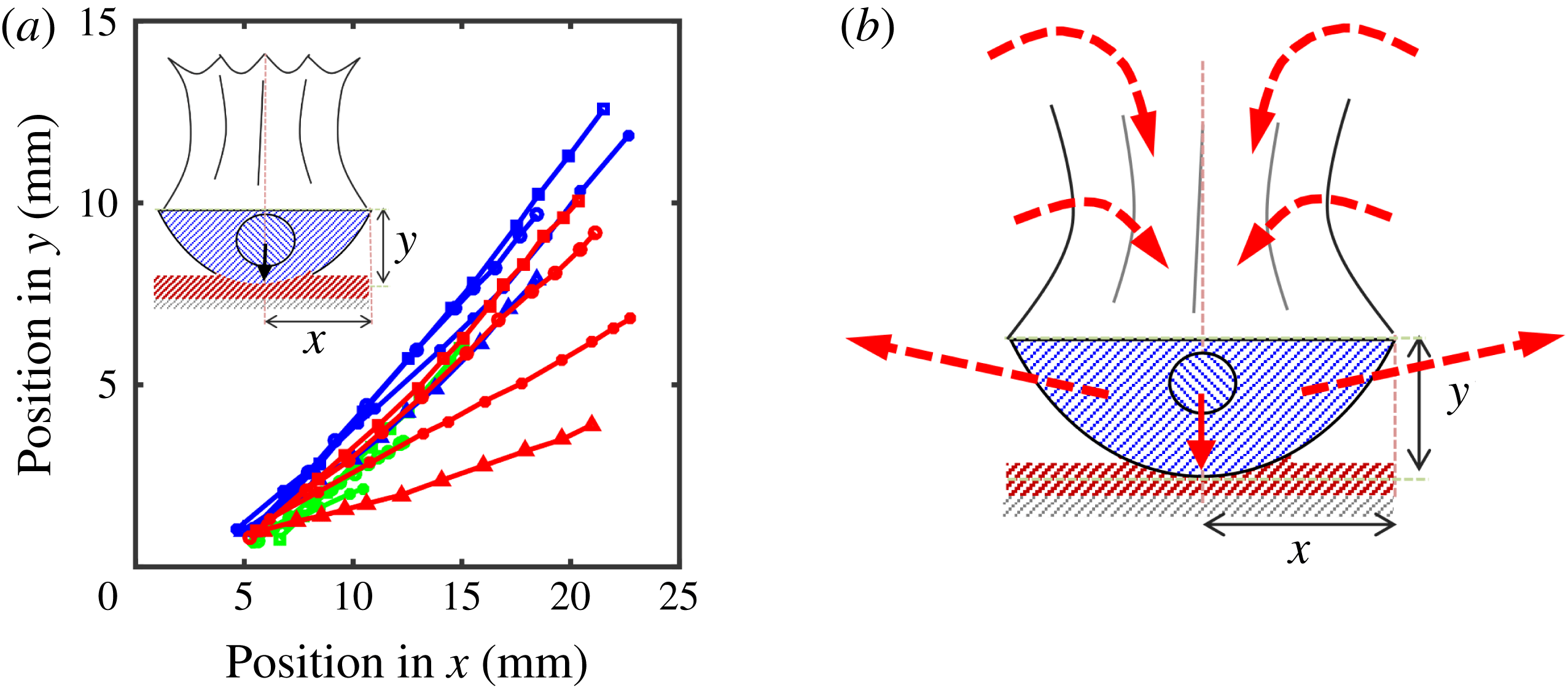
(a) Trajectories of the tip of the drop crown for different IPA film thicknesses
 $\unicode[STIX]{x1D6FF}^{\ast }=\unicode[STIX]{x1D6FF}/D_{H}=$
0.052 (▫); 0.038 (○); 0.026 (
 $\star$
); 0.013 (▵), for different viscosity glycerine/water drops 1250 cP (blue); 1000 cP (red); 500 cP (green). (b) The air flow forced by the growing volume inside the crown bowl.

3.2 Origin and thickness of the spray
Figure 1 shows the overall evolution of the spray sheet above the blue-coloured drop liquid crown. The early formation of this sheet is shown in figure 3, taken at larger magnifications without the blue dye. The earliest ejecta sheet breaks up into spray within a few microseconds after it emerges, perhaps owing to the vortex shedding mechanism discovered by Thoraval et al. (Reference Thoraval, Takehara, Etoh, Popinet, Ray, Zaleski and Thoroddsen2012). The horizontal velocity of this ejecta is
 ${\sim}100~\text{m}~\text{s}^{-1}$
(at our frame rates we measure
 $\simeq 80~\text{m}~\text{s}^{-1}$
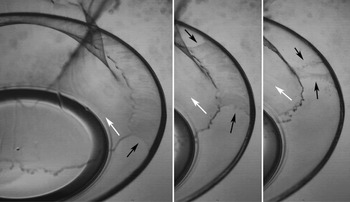
, but at 60 kfps we are underresolving this rapid dynamics, see Thoroddsen Reference Thoroddsen2002). These horizontally ejected microdroplets move rapidly away from the drop liquid crown, which only starts to rise out of the thin film in the fourth image of figure 3(b). These earliest droplets do not therefore impact on the inside crown wall. The images in figure 3(c) shows the microdroplets descending within the crown to hit the inside of the crown wall approximately 2 ms after impact. Figure 3(a) shows the same with different background lighting, highlighting that the crown sheet remains smooth before the spray sheet breaks up into the microdroplets.
The breakup of the spray sheet for 1000 cP glycerine/water drop impacting on IPA of thickness
 $\unicode[STIX]{x1D6FF}^{\ast }=0.052$
. The thick dark arc, on the right side of the frames, is the upper edge of the drop crown. The IPA sheet has a thinner band next to this crown edge, along which it ruptures much faster, moving around the periphery, as marked with the black arrows. The white arrows mark the edge of the thicker IPA section which ruptures at much slower speed. Times are shown at
 $t=3.51$
, 3.75 and 3.95 ms after impact.

The size distribution of the spray droplets is determined by the spray film thickness when it ruptures. Figures 1 and 3 show typical edge breakup. The spray film buckles as it is rapidly pulled towards the centreline above the crown (see arrows in figure 4
b). These continuous intact sheets often break first near their boundary with the top of the drop crown. Close-up images of this rupture allow us to measure the retraction speed
 $U_{s}$
of the edge of the rupture. This in turn allows us to estimate the spray sheet thickness from the well-known Taylor–Culick law (Taylor Reference Taylor1959; Culick Reference Culick1960), i.e.
 $$\begin{eqnarray}U_{s}=\sqrt{\frac{2\unicode[STIX]{x1D70E}}{\unicode[STIX]{x1D70C}\unicode[STIX]{x1D6FF}}}\Rightarrow \unicode[STIX]{x1D6FF}=\frac{2\unicode[STIX]{x1D70E}}{\unicode[STIX]{x1D70C}U_{s}^{2}}.\end{eqnarray}$$
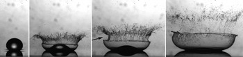
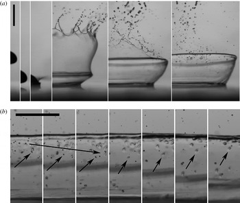
Uneven breakup of the spray sheet, in this realization, pulls in more spray droplets onto the left side (arrow in third frame), producing a non-axisymmetric patch distribution, made evident by the smooth crown on the right side. Times shown
 $t=20$
, 270, 400 and
 $680~\unicode[STIX]{x03BC}\text{s}$
after impact. Taken from videos under conditions in Thoroddsen et al. (Reference Thoroddsen, Etoh and Takehara2006a
), where
 $\unicode[STIX]{x1D6FF}^{\ast }\simeq 0.007$
. See also figure 8 from that paper.

This approach has been widely used to study crowns and ejecta, e.g. Thoroddsen et al. (Reference Thoroddsen, Thoraval, Takehara and Etoh2011), Opfer et al. (Reference Opfer, Roisman, Venzmer, Klostermann and Tropea2014). For the case of a glycerine drop onto an IPA film, shown in figure 5, the spray sheet is clearly much thinner in a band next to the crown and this part ruptures very rapidly, at
 $17~\text{m}~\text{s}^{-1}$
–
 $19~\text{m}~\text{s}^{-1}$
. Using (3.1) gives the corresponding
 $\unicode[STIX]{x1D6FF}_{spray}\sim 200$
nm. The thinner part of the sheet has therefore become thin enough to allow small thickness variations to rupture by surface forces. The upper part of this sheet breaks up with a much lower edge velocity of
 $U_{s}\simeq 3.7~\text{m}~\text{s}^{-1}$
, giving
 $\unicode[STIX]{x1D6FF}_{spray}\simeq 4~\unicode[STIX]{x03BC}\text{m}$
. This uneven thickness will result in vastly different droplet sizes, with fine spray of
 ${\sim}1~\unicode[STIX]{x03BC}\text{m}$
and large droplets of
 ${\sim}100~\unicode[STIX]{x03BC}\text{m}$
. The finer spray is therefore not clearly visible in the images, even though some drops can be followed approaching the crown and all are seen to produce Marangoni patches. We therefore conclude that all patches are due to the impact of these microdroplets. One strong support for this assertion arises when the spray sheet breaks up asymmetrically above the crown, which is subsequently manifest by an uneven distribution of Marangoni patches in the azimuthal direction. Figure 6 shows such a realization.
The thinning of the spray sheet adjacent to the top of the crown, as shown in figure 5, is likely due to the large jump in viscosity, where the drop and film sheets meet. This introduces essentially a fixed boundary which causes enhanced stretching of the faster moving spray sheet. Marangoni stress may also be involved, but assessing its significance would require a separate study.
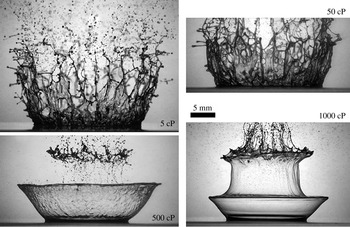
The effect of drop viscosity on the drop crown shape, for water/glycerine drops of
 $\unicode[STIX]{x1D707}_{d}=5$
, 50, 500 and 1000 cP, impacting at
 $U=8.2~\text{m}~\text{s}^{-1}$
onto
 $\unicode[STIX]{x1D6FF}^{\ast }=0.053$
thick IPA. The corresponding Reynolds number decreases with increasing viscosity as
 $Re_{d}=9350$
, 940, 98 and 51. The shapes are all shown at 2.5 ms after first contact, i.e. normalized time of
 $\unicode[STIX]{x1D70F}=t~U/D_{H}=4.1$
.

3.3 The drop crown evolution
The shape of the drop crown is strongly influenced by the drop viscosity, as well as the thickness of the substrate film, which we will now characterize in turn.
3.3.1 Changing drop viscosity
To form the regular bowl-shaped drop crown, studied herein, the viscosity of the drop must be large enough for the crown to remain intact following the high-speed impact. Figure 7 shows that only large
 $\unicode[STIX]{x1D707}_{d}$
values result in regular drop crowns and for
 $\unicode[STIX]{x1D707}_{d}$
values below 50 cP, the edge of the rising crown breaks up into irregular shapes before it can form the spray. At 50 cP the edge of the crown wall is still irregular, but the sheet below the edge is sufficiently intact to allow some holes to form. This is perhaps driven by the same Marangoni mechanism, even though it is difficult to follow the trajectories of spray droplets in this case. The regular crowns are therefore studied herein for drop viscosities
 $\unicode[STIX]{x1D707}_{d}\geqslant 500$
cP. This corresponds to
 $Re_{d}\leqslant 100$
. On the other hand
 $Re_{f}$
must be large enough to produce the spray sheet and propel it above the drop crown. For example in Kittel et al. (Reference Kittel, Roisman and Tropea2016), where for
 $Re_{f}\leqslant 6000$
, no spray sheet is observed.
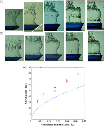
The changes in the angle of the drop crown as a function of the substrate-film thickness, for constant impact velocity
 $U=8.2~\text{m}~\text{s}^{-1}$
and
 $D_{H}=5.0$
mm (
 $Re_{d}\simeq 50$
;
 $We_{d}\simeq 6600$
). From left to right the film thickness increases from
 $\unicode[STIX]{x1D6FF}^{\ast }=\unicode[STIX]{x1D6FF}/D_{H}=0.013$
, 0.027, 0.053, 0.080 to 0.11. (a) For glycerine drop impacting on IPA. (b) For glycerine drop impacting on 2 cSt silicone oil. (c) The measured angles from the above experiments. Black squares for IPA and red triangles for 2 cSt silicone oil. The dashed blue curve represents the theoretical prediction of Fedorchenko & Wang (Reference Fedorchenko and Wang2004) in (3.3).

3.3.2 Substrate-film thickness
$\unicode[STIX]{x1D6FF}^{\ast }$
affects the crown angle
$\unicode[STIX]{x1D6FC}$


Figure 4(a) showed how the trajectories of the tip of the rising crown changes with the thickness
 $\unicode[STIX]{x1D6FF}$
of the thin film on the solid substrate. For all three different drop viscosities, the thicker film causes the crown to rise up at a steeper angle. This angle in turn affects the dynamics of the spray sheet, as the growth rate of the air volume inside the crown controls the air pressure and the strength of the inwards suction of the cylindrical spray sheet, as is sketched in figure 4(b). The crown angle
 $\unicode[STIX]{x1D6FC}$
is directly measured in figure 8, measured after the crown has emerged a significant distance from the film surface. It shows a monotonic increase in
 $\unicode[STIX]{x1D6FC}$
with the film thickness
 $\unicode[STIX]{x1D6FF}^{\ast }$
.
Roisman & Tropea (Reference Roisman and Tropea2002) have extended the theory of Yarin & Weiss (Reference Yarin and Weiss1995) to predict the emergence angle of the crown at its base, when the surface film and the drop are of the same low-viscosity liquid, i.e.
 $$\begin{eqnarray}\unicode[STIX]{x1D6FC}=\text{arccos}\left(\frac{(h_{1}-h_{2})(V_{n1}-V_{n2})^{2}}{(h_{1}+h_{2})(V_{n1}-V_{n2})^{2}-8\unicode[STIX]{x1D70E}/\unicode[STIX]{x1D70C}}\right),\end{eqnarray}$$
where
 $h_{1}$
and
 $h_{2}$
are the film thicknesses inside and outside of the crown and the corresponding velocities
 $V_{n1}$
and
 $V_{n2}$
are tangent along the substrate, moving with the crown base. In our case the impact Weber numbers are very large and the effect of surface tension is insignificant at the base of the crown. In this case the above expression reduces to
 $\cos (\unicode[STIX]{x1D6FC})=(h_{1}-h_{2})/(h_{1}+h_{2})$
. However, we cannot measure the film thicknesses on either side of the crown to use this expression. Fedorchenko & Wang (Reference Fedorchenko and Wang2004) constructed a simplified dynamical model producing an alternative formula based purely on the film thickness, which is more amenable to experimental comparison, i.e.
 $$\begin{eqnarray}\unicode[STIX]{x1D6FC}=\text{arccos}(1-4\ast \unicode[STIX]{x1D6FF}/D).\end{eqnarray}$$
This formula is plotted in figure 8(c) and shows the correct trend, but our measurements are consistently larger by approximately 35 %. There are two main reasons why this theory should not give quantitative agreement: first, the two liquids in our configuration are of significantly different densities; second, the large viscosity of the drop liquid will lead to a reduction in the momentum of the ejected sheet. It is beyond the scope of the current work to incorporate these facts into the above theoretical framework.
The finer details of the liquid in the substrate film are not important for the evolution of the crown shape. Figure 8(a) shows results for IPA films, while figure 8(b) is for a 2 cSt silicone oil film, which is immiscible with the drop liquid. The crown angles for the two film liquids are very similar.
Furthermore, we should point out that the earliest emergence of the spray sheet, from the substrate IPA, shows qualitatively difference behaviour compared to the drop crown, where
 $\unicode[STIX]{x1D6FC}$
for the spray, evolves rapidly, starting at
 ${\sim}0^{\circ }$
and rising to
 $\unicode[STIX]{x1D6FC}>90^{\circ }$
after only
 $400~\unicode[STIX]{x03BC}$
s, in the fourth image of figure 3(b). This is in agreement with the simple kinematic model presented in figure 8 of Thoroddsen et al. (Reference Thoroddsen, Thoraval, Takehara and Etoh2011). In this case, even defining
 $\unicode[STIX]{x1D6FC}$
becomes ambiguous at these very large
 $Re_{f}\sim 16\,000$
and
 $We_{f}\sim 11\,500$
, based on the IPA properties. Indeed the ejecta sheet (Thoroddsen Reference Thoroddsen2002) can be argued to be a distinct phenomenon, arising from different dynamics than the regular Edgerton crown, see Zhang et al. (Reference Zhang, Toole, Fezzaa and Deegan2012).
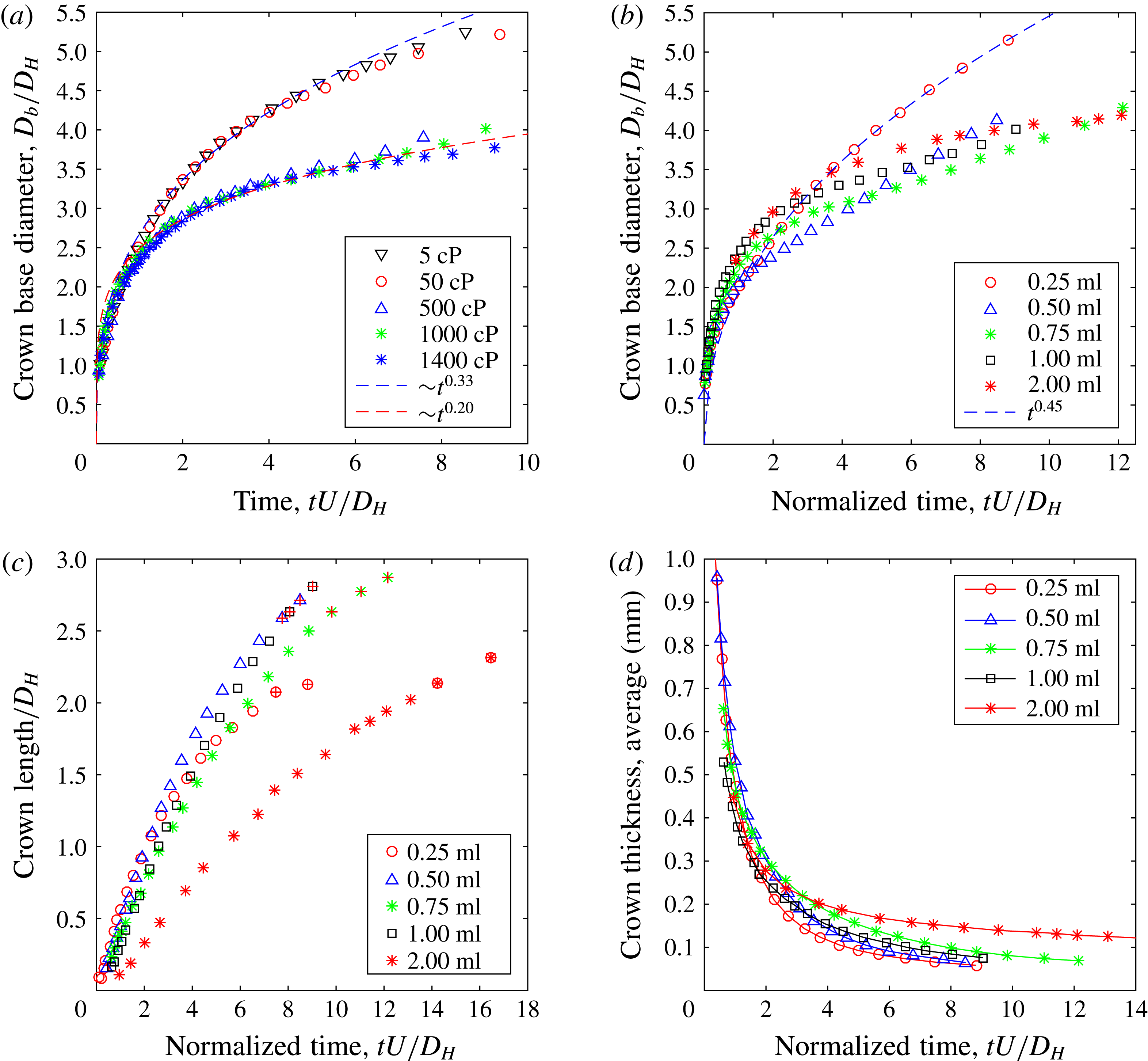
(a) The base diameter of the crown as a function of the drop viscosity, for a fixed film thickness of
 $\unicode[STIX]{x1D6FF}^{\ast }=0.053$
. (b) The base diameter of the crown for different film thicknesses
 $\unicode[STIX]{x1D6FF}^{\ast }$
, for
 $\unicode[STIX]{x1D707}_{d}\simeq 1000$
cP. (c) The arclength of the crown from the base to the tip, normalized by the drop diameter
 $D_{H}$
, over a range of film thicknesses
 $\unicode[STIX]{x1D6FF}^{\ast }$
. The highlighted symbols at the end of each curve indicate the time when breakup occurs. (d) An estimate of the upper bound of the crown thickness vs time, obtained by dividing the drop volume by the total area of the crown. The legends list the amount of liquid deposited on the glass plate 0.25 ml–2 ml, which corresponds to
 $\unicode[STIX]{x1D6FF}^{\ast }=0.013$
, 0.025, 0.039, 0.053 and 0.106 respectively.

In figure 9 we quantify these effects of varying
 $\unicode[STIX]{x1D707}_{d}$
and
 $\unicode[STIX]{x1D6FF}^{\ast }$
, by measuring the time evolution of the base diameter
 $D_{b}$
of the crown and its extent above the substrate film. These lengths are indicated in the fifth image of figure 3(a). Figure 9(a) shows that a large drop viscosity greatly slows down the radial growth of the base diameter of the crown. Furthermore, the approximate power laws
 $D_{b}=C(t-t_{o})^{\unicode[STIX]{x1D6FD}}$
, have different exponents
 $\unicode[STIX]{x1D6FD}$
. For the lower drop viscosities
 $\unicode[STIX]{x1D6FD}\simeq 0.33$
, while for the much larger
 $\unicode[STIX]{x1D707}_{d}$
, used mainly in our study, we get
 $\unicode[STIX]{x1D6FD}\simeq 0.20$
. The early theory of Yarin & Weiss (Reference Yarin and Weiss1995) had suggested
 $\unicode[STIX]{x1D6FD}\simeq 0.5$
, while modifications of Roisman & Tropea (Reference Roisman and Tropea2002) and others show that experiments are better fit with a smaller value of
 $\unicode[STIX]{x1D6FD}\simeq 0.43$
. See the review by Liang & Mudawar (Reference Liang and Mudawar2016). It is therefore clear that the dynamics for our typical impact conditions is qualitatively different.
Figure 9(b) shows that the film thickness also changes these power laws greatly, for a fixed value of drop viscosity
 $\unicode[STIX]{x1D707}_{d}\simeq 1000$
cP. Only for the thinnest film is the power exponent
 $\unicode[STIX]{x1D6FD}\simeq 0.45$
.
We conclude that both
 $\unicode[STIX]{x1D707}_{d}$
and
 $\unicode[STIX]{x1D6FF}^{\ast }$
have strong effects on the motion of the base diameter and this prevents meaningful comparison with earlier theories for impacts with the same low-viscosity liquids in the drop and pool.
The same is true for the vertical extent of the bowl, shown in figure 9(c), where the growth rate of the arclength is significantly reduced when the film becomes thicker
 $\unicode[STIX]{x1D6FF}^{\ast }=0.106$
. This will affect the stretching rate and crown thickness. It also suggests that the transition from thin-film dynamics occurs in our configuration when
 $\unicode[STIX]{x1D6FF}^{\ast }\sim 0.10$
, i.e. for much thinner films than suggested in other studies. The crown angle also seems to asymptote to
 $90^{\circ }$
when
 $\unicode[STIX]{x1D6FF}^{\ast }$
approaches 0.15 in figure 8(c).
Stretching and breakup of the crown from impact of glycerine drop on IPA, under similar conditions as in figure 5. Shown at
 $t\simeq 3.8$
, 4.9, 6.5, 9.2 and 15.2 ms after impact.

3.3.3 Stretching of the drop crown wall
The thickness of the drop liquid crown and its rate of expansion and stretching may influence the hole formation and now we attempt to quantify these underlying factors.
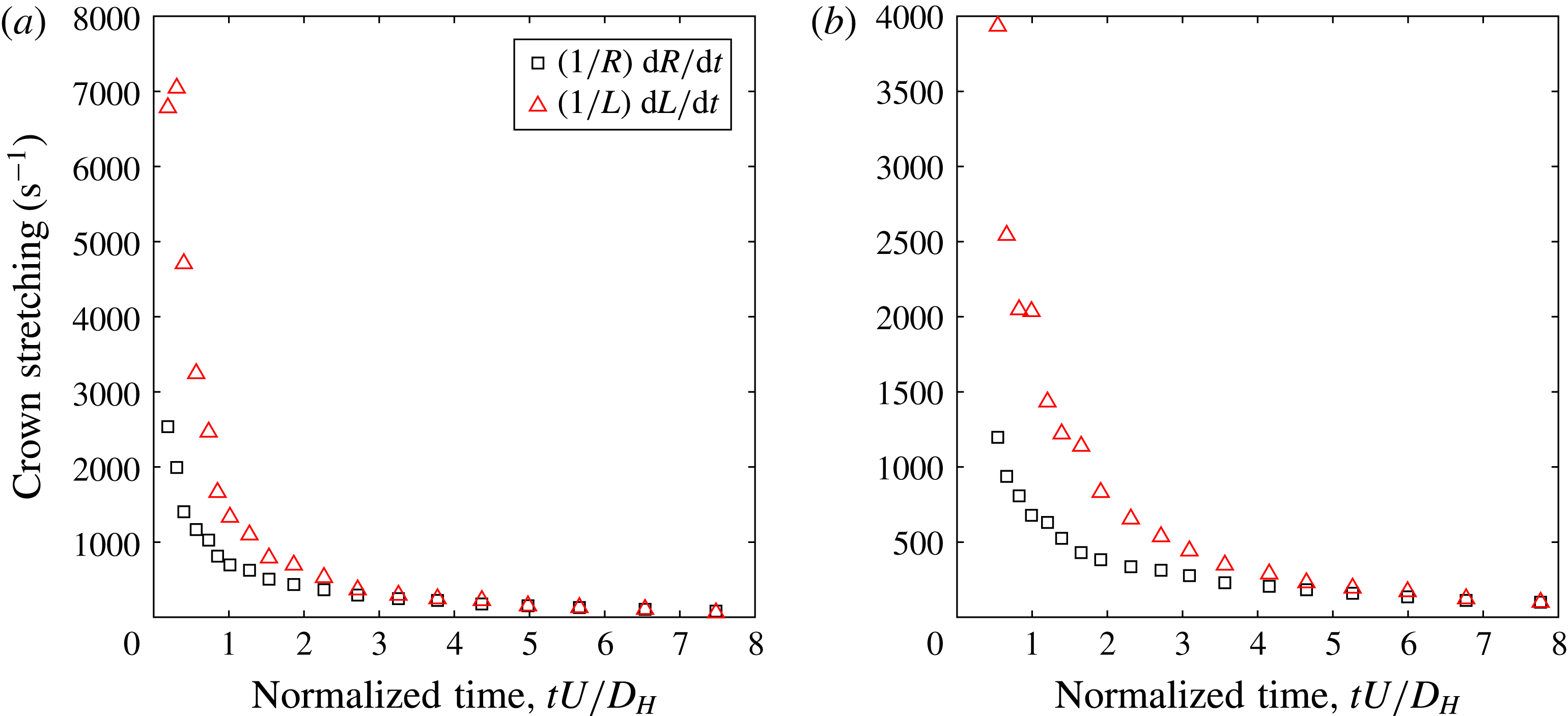
The rate of stretching of the crown wall by its expansion, arises from both the radial and vertical motions, as marked by the arrows in figure 3(a). The azimuthal rate-of-stretching term comes from the increase in crown radius with time, away from the axis of symmetry, i.e.
 $$\begin{eqnarray}\frac{1}{R}\frac{\text{d}R}{\text{d}t}\end{eqnarray}$$
while the vertical stretching is from the gradient of the tangential velocity (
 $u_{t}$
) along the sheet as it grows in the vertical direction,
 $\unicode[STIX]{x2202}u_{t}/\unicode[STIX]{x2202}z$
, with
 $z$
measured along the sheet. The former term, in (3.4), is approximated from the side view video clips, while the second term is more difficult to estimate. We can measure the vertical length of the crown (angled arrow in figure 3
a), and see how this elongates with time, but we do not know the magnitude of the drop liquid velocity entering the crown from the bottom edge. Here, there is no deep pool of crown liquid as in the identical pool liquid case, so the crown-liquid comes from the edge of the spreading drop. However, once the microdroplets start hitting the crown wall this second component can be directly measured by following the centres of the patches imprinted on the crown by these microdroplets. This can only be done for a short time interval, before the crown wall breaks up into the network of filaments. This is highlighted, for one realization, by the arrows in figure 10. Following these patches we conclude that the stretching of the sheet, driven by its inertia, is more important at this stage than the small inlet velocity from the base of the crown. Therefore, ignoring the flow from the film, we estimate the two stretching rates in figure 12. The initial stretching is much stronger in the tangential direction along the crown wall, but quickly reduces and approached close to the radial azimuthal stretching rate, for both of the smallest film thicknesses.
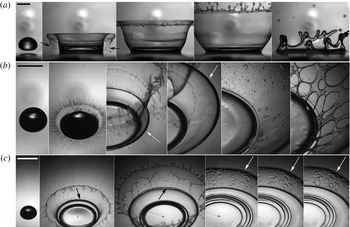
The effects of the difference of surface tension
 $\unicode[STIX]{x0394}\unicode[STIX]{x1D70E}$
on hole formation. (a)
 $\unicode[STIX]{x0394}\unicode[STIX]{x1D70E}=0$
. For
 $t=-0.08$
, 0.90, 1.90, 3.53 and 21.20 ms.
 $Re_{d}=43$
,
 $We_{f}=8480$
, for
 $\unicode[STIX]{x1D6FF}=0.27$
mm. (b) Positive Marangoni,
 $\unicode[STIX]{x0394}\unicode[STIX]{x1D70E}=41~\text{mN}~\text{m}^{-1}$
, for
 $t=-0.03$
, 0.10, 1.10, 3.40, 7.80 and 9.73 ms.
 $Re_{d}=78$
,
 $We_{f}=14.730$
. (c) Drop of silicone oil onto a film of toluene, where the difference in surface tension is negative (negative Marangoni) holes
 $\unicode[STIX]{x0394}\unicode[STIX]{x1D70E}=-8~\text{dyn}~\text{cm}^{-1}$
, for
 $t=-0.13$
, 0.77, 2.03, 5.77, 6.27 and 6.47 ms.
 $Re_{d}=127$
,
 $We_{f}=11\,880$
. The scale bars are all 5 mm long. See also supplementary movies 2 and 3 for (b) and (c) respectively.

The stretching rates of the crown wall, evaluated at the centre of the crown. For the two thinnest films on the substrate in figure 9(d). (a)
 $\unicode[STIX]{x1D6FF}^{\ast }=0.013$
and (b)
 $\unicode[STIX]{x1D6FF}^{\ast }=0.026$
. Note the different vertical scales in the two panels.

3.3.4 Wall thickness of the drop crown
We now estimate the thickness of the crown wall using three different methods: i.e. (i) based on the average crown area, (ii) by the volume of the ligaments left after the breakup and (iii) using the Taylor–Culick speed of the hole growth.
First, we estimate an upper bound for the thickness of the drop crown by simply measuring the total area of the crown and dividing that into the volume of the drop, thereby giving its average thickness. Here we have included the circular area of the base, where the centre of the spreading drop will leave a disc of the viscous liquid which is probably thicker than the crown wall. Figure 9(d) shows how this average thickness is reduced with time for different substrate-film depths. For
 $\unicode[STIX]{x1D6FF}^{\ast }\leqslant 0.053$
this average thickness, based on the measurements in figure 9(d), reaches
 ${\sim}70~\unicode[STIX]{x03BC}\text{m}$
by the time the sheet ruptures through the Marangoni holes. Keep in mind that this is an upper bound estimate of the thickness. The most rapid thinning occurs within the normalized time
 $\unicode[STIX]{x1D70F}=tU/D_{H}\leqslant 2.5$
.
In contrast, for a drop impact onto the same pool liquid, the base thickness of the crown sheet grows in time. Cossali et al. (Reference Cossali, Marengo, Coghe and Zhdanov2004) showed this in approximate measurements, using a bottom view, to estimate the crown base thickness by taking the difference between the outer and inner diameter. They have found this thickness increases significantly with dimensionless time. Fujimoto et al. (Reference Fujimoto, Ogino, Takuda and Hatta2001) estimated the crown thickness numerically. They concluded that the crown thickness decreases by reducing surface tension. See also figure 6 in Thoroddsen (Reference Thoroddsen2002), where the width of the ejecta base clearly grows with time.
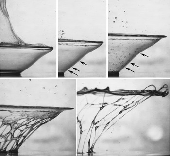
The breakup of the crown into filaments, for glycerine drop impacting on IPA. The filament size in the last frame, combined with the area between the four holes in the third frame, is used to estimate the wall thickness. Note the smooth crown wall in the first frame, before the spray sheet ruptures sends microdrops down towards the inside wall. Times shown at
 $t=2.3$
, 4.6, 7.0, 8.2, 9.4 and 10.4 ms after impact. The scale bar is 2 mm long.

Based on the above average estimate, the opposite occurs in our configuration, with the crown wall becoming progressively thinner. This we argue on the finite volume of drop liquid and minimal replenishment of the crown from the film liquid, which has been ejected into the spray sheet. This only changes if the film becomes significantly thicker, as will be shown in figure 18.
Second, we estimate the wall thickness by measuring the size of the liquid filaments, which are left behind following the crown breakup. This we do by identifying a specific area in the crown where four holes meet, as is shown in figure 13. We then back out the area of the crown which ended up providing the volume to the filament. This method leads to a direct estimate of the crown thickness. This was done for isolated cases to check whether there is a relationship between viscosity and the crown thickness. We find, in the case of pure glycerol (1400 cP at
 $t\simeq 9$
ms) the crown thickness was (
 $\unicode[STIX]{x1D6FF}_{crown}=31\pm 7~\unicode[STIX]{x03BC}$
m), while for smaller viscosities (1000 cP, at
 $t\simeq 8$
ms) we get
 $\unicode[STIX]{x1D6FF}_{crown}=21\pm 6~\unicode[STIX]{x03BC}$
m and for the lowest viscosity (500 cP, at
 $t\simeq 5$
ms),
 $\unicode[STIX]{x1D6FF}_{crown}=16\pm 4~\unicode[STIX]{x03BC}$
m. Keep in mind that the crown thins rapidly by the stretching (see figure 9
d) and the times listed above correspond to the start of the measurement, for example frame 3 in figure 13. The ranges for
 $\unicode[STIX]{x1D6FF}_{crown}$
are based on a few realizations, but other errors could arise from us not knowing the flow within the thin films during the latter’s contraction into the cylindrical threads. These values indicate that the higher-viscosity crowns take longer to thin out. Keep in mind that the timing of the crown breakup is determined by the spray trajectories and not directly by the drop viscosity.
Third, we look at the speed of hole growth after punctures form. We find that drop viscosity is not the primary determinant of this speed, rather the thickness of the crown wall is more important. For example for the three different drop viscosities,
 $\unicode[STIX]{x1D707}_{d}=500$
cP, 1000 cP and 1400 cP impacting on IPA, isolated holes give us speeds of approximately
 $1.3~\text{m}~\text{s}^{-1}$
,
 $1.9~\text{m}~\text{s}^{-1}$
and
 $2.1~\text{m}~\text{s}^{-1}$
respectively. Using the Taylor–Culick law (equation 3.1) with average
 $\unicode[STIX]{x1D70E}$
, this would predict
 $\unicode[STIX]{x1D6FF}_{crown}\sim 29\pm 10~\unicode[STIX]{x03BC}$
m, in overall agreement with the above estimates.
However, the discussion in Savva & Bush (Reference Savva and Bush2008) shows when the crown viscosity can influence the Taylor–Culick prediction, in terms of a characteristic viscous time scale, using our notation
 $$\begin{eqnarray}\unicode[STIX]{x1D70F}_{vis}=\frac{\unicode[STIX]{x1D707}_{d}\;\unicode[STIX]{x1D6FF}_{crown}}{2\,\unicode[STIX]{x1D70E}_{f}},\end{eqnarray}$$
which takes a value of 0.6 ms for pure glycerine and 0.4 ms for 1000 cP water/glycerine drop, when using the IPA surface tension, see Thoraval & Thoroddsen (Reference Thoraval and Thoroddsen2013). We should therefore expect viscous forces to play some role in the initial hole expansion rates.
The formation of holes in the crown, comparing patch structure for positive and negative
 $\unicode[STIX]{x0394}\unicode[STIX]{x1D70E}$
. (a) Close up of the formation of holes in the crown for positive Marangoni stress, glycerine/water 500 cP onto IPA. Times at
 $t=-0.27,-0.13$
, 0, 0.33, 2.07, 2.67, 3.07, 3.37, 3.40 and 3.57 ms relative to the fine drop hitting the crown.
 $Re_{d}=78$
,
 $We_{f}=14.730$
, with
 $\unicode[STIX]{x0394}\unicode[STIX]{x1D70E}=\unicode[STIX]{x1D70E}_{d}-\unicode[STIX]{x1D70E}_{f}=42~\text{mN}~\text{m}^{-1}$
(b) Close up of the formation of holes in the crown for negative Marangoni stress, silicone oil 350 cSt onto toluene, having
 $\unicode[STIX]{x0394}\unicode[STIX]{x1D70E}=\unicode[STIX]{x1D70E}_{d}-\unicode[STIX]{x1D70E}_{f}=-7.4~\text{mN}~\text{m}^{-1}$
. Times shown are
 $t=0.33$
, 2.00, 2.62, 2.90, 2.97, 3.03 and 3.20 ms relative to start of radial expansion from fine drop hitting crown. Note the small dot at the centre of each patch. The rupture occurs before the fifth image.
 $Re_{d}=127$
,
 $We_{f}=11\,880$
. The scale bars are 2 mm long. See also supplementary movie 4.

3.4 Patch growth rates and hole formation
The high-speed video clips allow us to track individual spray droplets and verify the direct connection between droplets and hole formation. This is done in figures 14(a) and 15 and is clear in the supplementary movies. The frame sequences in figure 11(b,c) show that the crown surface remains smooth until the spray droplets reach it. The arrows in the figures point out the top of the drop crown, where it connects to the spray sheet. When the fine droplets impact on the crown wall, they merge with the crown liquid, if the two liquids are miscible. However, as the two liquids have different surface tensions, strong Marangoni effects are observed. The difference between the two surface tensions
 $\unicode[STIX]{x0394}\unicode[STIX]{x1D70E}=\unicode[STIX]{x1D70E}_{drop}-\unicode[STIX]{x1D70E}_{film}$
, can be of either sign. When the drop and the film are of the same liquid (
 $\unicode[STIX]{x0394}\unicode[STIX]{x1D70E}=0$
), no holes are formed. Figure 11(a), shows such a case, where glycerine droplets from the ejecta are slingshot inwards to hit the crown, see arrows in the second image. This produces some local waves on the crown wall, but no ruptures. On the other hand when the two surface tensions are different, plus or minus, holes are always formed, as shown below.
3.4.1 Marangoni holes from divergent
$\unicode[STIX]{x0394}\unicode[STIX]{x1D70E}$
-stress

For lower-
 $\unicode[STIX]{x1D70E}$
spray (
 $\unicode[STIX]{x0394}\unicode[STIX]{x1D70E}>0$
) the divergence in the surface stress creates locally a thin Marangoni patch in the crown film. Such thinning patches are well known, especially for films on solid substrates, see for example Jensen & Grotberg (Reference Jensen and Grotberg1992). These films eventually puncture at a random location within the thin film, or at its edge. In figure 14(a) we follow the trajectory of a single splash droplet until it hits the crown, which is followed by the growth of the thinning patch, leading to the rupture in the eighth image. Here the puncture starts at its upper edge. This puncture rapidly removes the thin film inside the patch, leaving a growing hole with a thick rim. The rupture speed of
 $U_{thinfilm}\simeq 14~\text{m}~\text{s}^{-1}$
, suggests it is submicron in thickness, based on (3.1). Thoroddsen et al. (Reference Thoroddsen, Etoh and Takehara2006a
) measured similar rupture velocities for this thin film inside the patches.
Splashing of immiscible spray, when a drop of 500 cSt silicone oil impacts on a thin film of methanol,
 $D_{H}=6$
mm,
 $Re_{d}=105$
,
 $We_{f}=14\,820$
. (a) Times shown at
 $t=-0.55,-0.05$
, 0.08, 2.05, 5.05 and 6.42 ms. (b) Close up of the impact of a single microdroplet hitting the crown, for
 $t=7.10$
, 7.42, 8.00, 8.72, 9.50 and 10.28 ms. Note that the patch does not grow in size. The scale bars are both 5 mm long.

3.4.2 Compressive Marangoni holes
Surprisingly, we also see hole formation when the film liquid has larger surface tension than the drop, i.e.
 $\unicode[STIX]{x0394}\unicode[STIX]{x1D70E}=\unicode[STIX]{x1D70E}_{drop}-\unicode[STIX]{x1D70E}_{film}<0$
, as is shown in figure 14(b). This is realized by impacting a 350 cSt silicone oil drop onto a film of toluene, where
 $\unicode[STIX]{x0394}\unicode[STIX]{x1D70E}=-7.4~\text{mN}~\text{m}^{-1}$
. However, we see qualitatively different rupture dynamics for the resulting convergent surface stress. A prominent patch still occurs, but it has a characteristic dimple at the centre, which is absent in the divergent stress above (compare panels (a) and (b) in figure 14). The ruptures always starts near the centre of this spot, i.e. at the dimple. The compressive Marangoni stresses pull liquid towards the centre of the patch, thereby generating recirculating regions which for our miscible configuration enhances the mixing of the microdroplet with the crown liquid. The sketch in figure 2(c) shows the possible induced flow field within the film. Such circulations are for example visualized by the experiments of Tan & Thoroddsen (Reference Tan and Thoroddsen1998) who studied the impact of a drop of water on a film of pure glycerol sitting on a solid substrate, producing a configuration where
 $\unicode[STIX]{x0394}\unicode[STIX]{x1D70E}\simeq -8~\text{mN}~\text{m}^{-1}$
. Those convective motions are unstable and form an intricate flower-like pattern. In our configuration we have two free surfaces which enhances the induced rotation and rapid mixing of the microdrop liquid into the much higher-viscosity crown liquid. In figure 2(c) we propose a possible mechanism where the direction of the gradient can be inverted on the opposite side from the microdrop impacts. We do indeed see a sudden expansion of the dimple, just before the rupture begins, as is shown in supplementary movie 4 accompanying figure 14(b).
Figure 15 shows a case where
 $\unicode[STIX]{x0394}\unicode[STIX]{x1D70E}=-7.3~\text{mN}~\text{m}^{-1}$
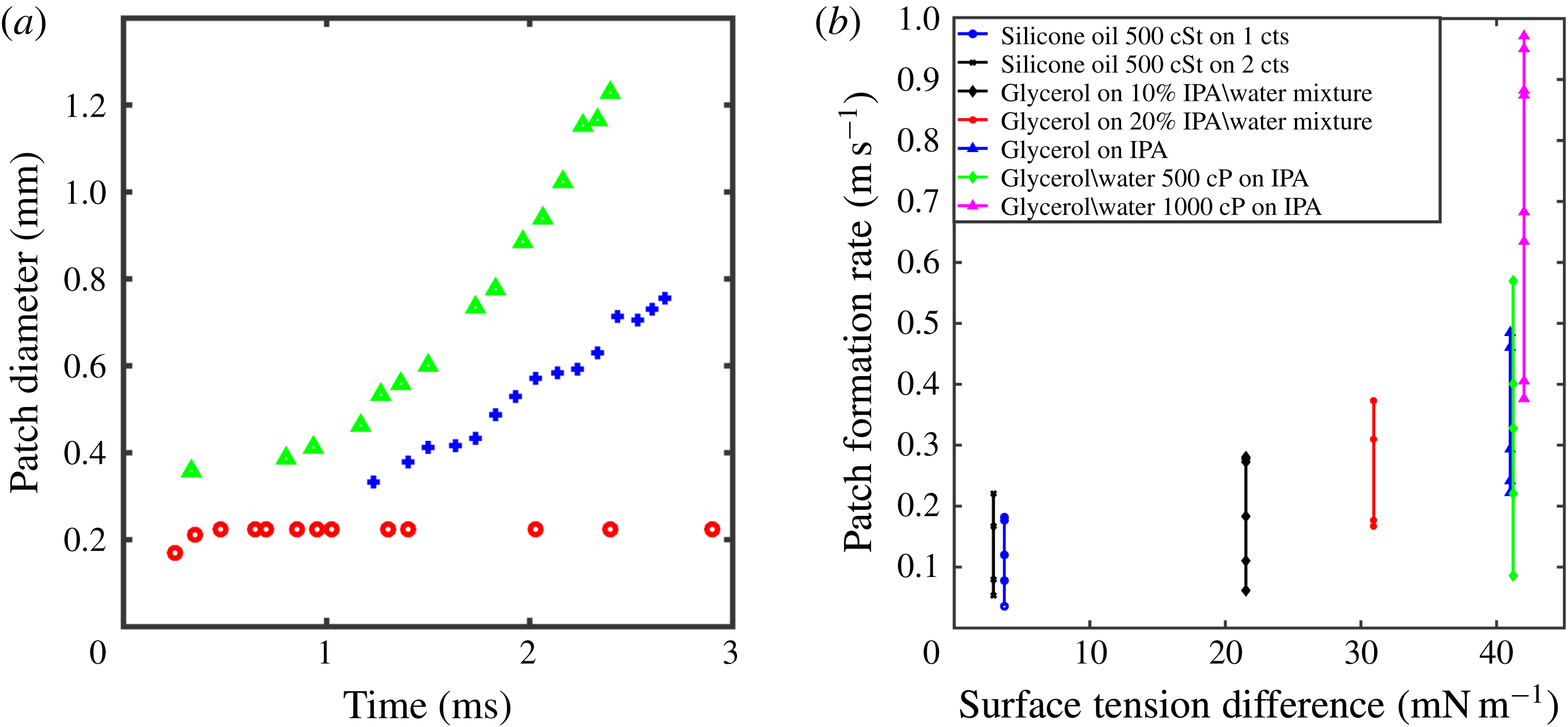
, but the two liquids are immiscible. Here, no ruptures are produced and the spot does not grow much with time because the fixed triple line does not produce convective motions, as in the miscible cases. Figure 16(a) compares growth rates for different signs of
 $\unicode[STIX]{x0394}\unicode[STIX]{x1D70E}$
.
(a) Comparison of patch growths for
 $\unicode[STIX]{x0394}\unicode[STIX]{x1D70E}>0$
(green
 $\triangle$
);
 $\unicode[STIX]{x0394}\unicode[STIX]{x1D70E}<0$
(blue
 $+$
); immiscible liquids (red
 $\bigcirc$
). (b) The range of growth rates of the Marangoni patches for all tested configurations.

3.5 Important variables
Having verified, by direct imaging, that the holes are due to the impacts of individual spray droplets, we now attempt to systematically vary the parameters which most influence the hole formation, to see how the growth rate of the thinning patch is affected. The impact velocity
 $U$
has been kept constant throughout (
 $\simeq 8.2~\text{m}~\text{s}^{-1}$
), but
 $\unicode[STIX]{x0394}\unicode[STIX]{x1D70E}$
,
 $\unicode[STIX]{x1D707}_{drop}$
and
 $\unicode[STIX]{x1D6FF}$
are varied. Figure 16(b) shows the Marangoni-driven growth rate of the thinning patch. It includes all of the data and reveals that overall the patches grow faster for larger
 $\unicode[STIX]{x0394}\unicode[STIX]{x1D70E}$
, while the interplays of
 $\unicode[STIX]{x0394}\unicode[STIX]{x1D70E}$
,
 $\unicode[STIX]{x1D707}_{drop}$
and
 $\unicode[STIX]{x1D6FF}$
are unclear. The large range of values for each
 $\unicode[STIX]{x0394}\unicode[STIX]{x1D70E}$
arises from the variability of conditions included.
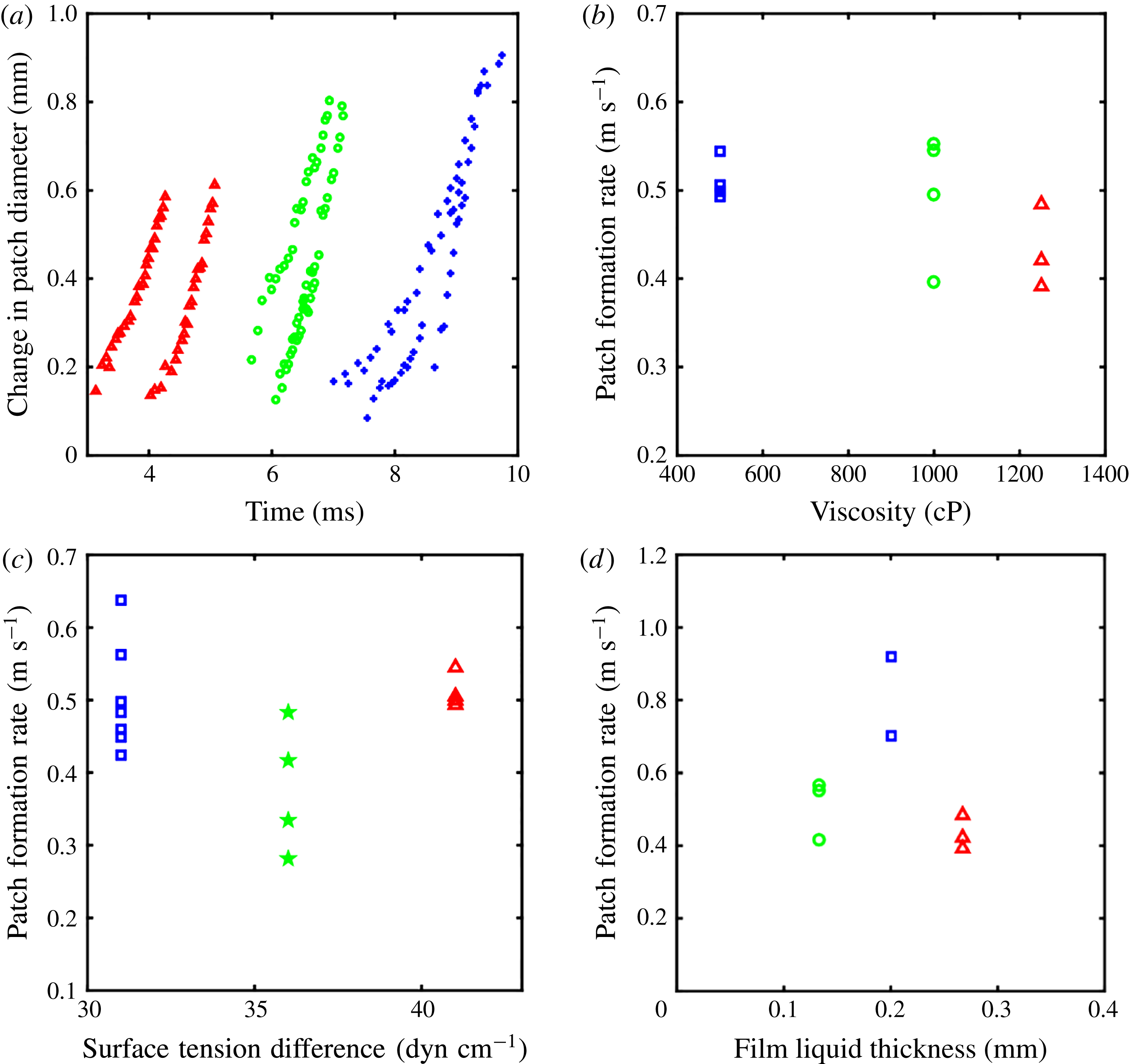
We next select impact conditions where only one of the variables is changed. This has the drawback of limiting the range of the particular physical variable. Figure 17(a,b) looks at the influence of drop viscosity. In panel (a) we track growth of the radius of the thinning patches with the time from impact. For lower drop viscosity the crown/spray evolution is faster and the droplets impact the crown wall earlier. The spray impact and patches therefore appear much earlier for the lower-viscosity drops. The early growth rate is lowest for the largest drop viscosity. However, there is no clear trend, only a weak reduction in the growth rate for higher drop viscosity, in figure 17(b).
(a) Growth of patch diameter for different water/glycerol drops impacting a film of IPA. (Red
 $\triangle$
) 500 cP; (green
 $\bigcirc$
) 1000 cP; (blue
 $\star$
) 1260 cP. (b) Patch growth rate for different water/glycerol drops impacting on IPA film. (Blue
 $\Box$
) 500 cP; (green
 $\bigcirc$
) 1000 cP; (red
 $\triangle$
) 1260 cP. (c) Patch growth rate of water/glycerol (500 cP) drops impacting on different water/ethanol films for
 $\unicode[STIX]{x0394}\unicode[STIX]{x1D70E}$
. (Blue
 $\Box$
)
 $\unicode[STIX]{x0394}\unicode[STIX]{x1D70E}=31~\text{dyn}~\text{cm}^{-1}$
; (green
 $\star$
)
 $\unicode[STIX]{x0394}\unicode[STIX]{x1D70E}=36~\text{dyn}~\text{cm}^{-1}$
; (
 $\text{red}\,\triangle$
)
 $\unicode[STIX]{x0394}\unicode[STIX]{x1D70E}=41~\text{dyn}~\text{cm}^{-1}$
. (d) Patch growth rate for a glycerol drops impacting on IPA films with different film thicknesses. (Green
 $\bigcirc$
)
 $\unicode[STIX]{x1D6FF}=0.13$
mm; (blue
 $\Box$
)
 $\unicode[STIX]{x1D6FF}=0.20$
mm; (red
 $\triangle$
)
 $\unicode[STIX]{x1D6FF}=0.27$
mm.

The breakup of the crown for the deepest pool of
 $\unicode[STIX]{x1D6FF}^{\ast }=\unicode[STIX]{x1D6FF}/D_{H}=0.11$
. Drop is pure glycerol impacting an IPA pool. Time shown at
 $t=0$
, 3.28 and 13.9 ms after first contact. The crown consists of both drop and pool liquid, as is clear during the breakup stage, where the blue drop liquid has ‘dewetted’ from sections of the wall.

In figure 17(c) we use water/glycerine on water/IPA mixtures to vary
 $\unicode[STIX]{x0394}\unicode[STIX]{x1D70E}$
, over a limited range of values. Here again, the spread in the data is larger than any trend. Keep in mind that the growth rate can be affected by surrounding patches and we must find isolated spray drop impacts to evaluate the spreading rates.
In figure 17(d) the effect of only varying the film thickness on the substrate
 $\unicode[STIX]{x1D6FF}$
, shows no clear trend.
4 Discussion and conclusions
Herein we have attempted to determine what mechanism is responsible for the Marangoni holes which form in our impact crowns. By using close-up high-speed video imaging, we have shown conclusively that the progenitor of each hole is identified with a spray droplet hitting the crown wall. This observation rules out Rayleigh–Taylor instability, which is also reinforced by the fact that holes are not produced for regular same-liquid impacts where the crown experiences similar deceleration.
The timing of the onset of the Marangoni holes is fundamentally controlled by the breakup of the spray sheet into microdroplets, which subsequently impact the inner surface of the crown wall. This breakup of the sheet and the trajectories of the spray droplets depend in turn on a number of factors, such as the thickness of the film on the substrate, the viscosity of the drop as well as the relative surface tensions. The evolution of the holes is dependent on separate factors, such as the current thickness of the crown wall and the difference in the surface tension of the two liquids. These interwoven factors make it difficult to separate the roles of
 $\unicode[STIX]{x0394}\unicode[STIX]{x1D70E}$
,
 $\unicode[STIX]{x1D707}_{d}$
and
 $\unicode[STIX]{x1D6FF}^{\ast }$
.
Myriad microdroplets from the spray hit the inside of the crown wall and start their individual Marangoni patches. However, only a small fraction progress to rupture the sheet and form holes. Many of the patches stop growing when adjacent punctured holes are formed, which expand and compress the film within nearby patches which have not yet ruptured.
Furthermore, there are three distinct velocities which emerge in the hole formation: (i) the spreading speed of the Marangoni patches (
 $u\sim 0.5~\text{m}~\text{s}^{-1}$
) following the impact of the spray microdroplet; (ii) the rupture speed of the sub-micron thin film inside the patch (
 $u\sim 15~\text{m}~\text{s}^{-1}$
) and finally (iii) the growth rate of the hole (
 $u\sim 2~\text{m}~\text{s}^{-1}$
).
Our secondary focus has been on the role of the difference in the surface tension between the drop and film liquids. In addition, the viscosity of the spray droplets is much smaller than that of the drop-produced crown, the viscosity will thereby be locally reduced by mixing the two liquids. This may change the local stretching of the crown, which is driven by its growth in the azimuthal and vertical directions. However, the sizes of the patches grow much faster than the local stretching, which is made clear by the adjacent holes meeting and even compressing their neighbours, when forming the network-like mesh. We therefore conclude that Marangoni-driven motions play the primary role. This is easily understood for configurations with divergent surface Marangoni stress, when the spray droplet has lower surface tension than the drop (
 $\unicode[STIX]{x1D70E}_{d}>\unicode[STIX]{x1D70E}_{f}$
). On the other hand, this conclusion is tested by our observation that compressive stress (
 $\unicode[STIX]{x1D70E}_{d}<\unicode[STIX]{x1D70E}_{f}$
) can also promote hole formation.
The imaging shows qualitatively different rupture dynamics when
 $\unicode[STIX]{x0394}\unicode[STIX]{x1D70E}$
changes sign. For compressive Marangoni, the surface stress pulls the crown liquid towards its centre, as sketched in figure 2(c). This is manifest by a prominent dimple at the centre of each patch (figure 14
b). No such dimple is present for the divergent Marangoni stresses. One can image a configuration, where the drop has diffused through the sheet and the induced motions have inverted the liquid on the opposite side of the crown sheet, where
 $\unicode[STIX]{x1D70E}$
is now lower at the centre of the patch, promoting a central rupture. Further understanding of this dynamics is primarily hampered by us not knowing the thickness of the crown wall, which is a strong function of time as it is stretched axially and azimuthally. How thick is the wall relative to the microdrop? Solving this will require future interferometric measurements, or detailed numerical simulations. However, we can estimate the time scale of the rotation in the central dimple, which we interpret as being the lens of the microdroplet liquid (Tan & Thoroddsen Reference Tan and Thoroddsen1998; Kim et al.
Reference Kim, Muller, Shardt, Afkhami and Stone2017) as
 $\unicode[STIX]{x1D70F}_{overturn}\sim \unicode[STIX]{x1D6FF}_{crown}/u_{e}$
, where
 $u_{e}$
is the expansion velocity of the patch
 ${\sim}0.3~\text{m}~\text{s}^{-1}$
. This gives
 $\unicode[STIX]{x1D70F}_{overturn}\sim 67~\unicode[STIX]{x03BC}$
s, well within the breakup time of these patches.
The impacting microdrop does not rupture the crown when it is immiscible (figure 15). Keep in mind that for immiscible liquids, when the net surface tension acting on a lens of liquid becomes positive, local thinning can lead to ruptures. This would be determined by the spreading parameter at the triple line, see De Gennes, Brochard-Wyart & Quéré (Reference De Gennes, Brochard-Wyart and Quéré2004) and Li et al. (Reference Li, Al-Otaibi, Vakarelski and Thoroddsen2014).
It remains to be determined whether the outer surface of the drop crown is covered with a thin layer of the lower-viscosity film, connecting the surface film to the spray sheet. Determining this is beyond the scope of the current work, but we do not observe a possible dewetting of such a film. Josserand & Zaleski (Reference Josserand and Zaleski2003) showed numerically that the ejecta has a thin layer of pool liquid covering its outer edge, while the experiments in Thoroddsen (Reference Thoroddsen2002) showed mostly pool liquid in the ejecta when the pool and drop are of the same low-viscosity liquid. Considering our large difference in viscosities and the extended spray sheet above the crown, we expect mostly drop liquid in this crown. This changes however when the pool becomes deeper. In figure 18 the crown appears mostly to consist of the pool liquid, as the blue-coloured drop dewets from the inside of the crown, even before the ruptures begin.
Acknowledgements
This study was supported by King Abdullah University of Science and Technology (KAUST) under grant URF/1/2621-01-01. LW was a student intern at KAUST and performed many of the experiments.
Supplementary movies
Supplementary movies are available at https://doi.org/10.1017/jfm.2018.178.