Introduction
Over the past decade, researchers have been extending the boundaries of Li-ion battery-based energy storage systems by utilizing new approaches that enable high capacity systems based on non-intercalation cathodes, such as sulfur, selenium, and oxygen.Reference Yin, Xin, Guo and Wan1–Reference Christensen, Albertus, Sanchez-Carrera, Lohmann, Kozinsky, Liedtke, Ahmed and Kojic6 Although significant effort has been put into the cathode side of these systems, the success of these high capacity energy storage systems relies on the realization of the promise of Li-metal anodes.
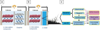
Li metal has many advantageous properties, including an extremely high theoretical specific capacity (3860 mAh g–1), the lowest electrochemical potential (–3.040 V versus standard hydrogen electrode), and low density (0.59 g cm–3), which make it a very desirable electrode for energy storage devices. However, while primary Li batteries are used for numerous commercial applications, rechargeable Li-metal batteries that utilize Li-metal anodes have not been as successful, although they have been investigated in the last 40 years.Reference Whittingham7–Reference Takeuchi, Marschilok, Davis, Leising and Takeuchi9 This has been attributed to several underlying issues—among them the growth of high surface area Li dendritic structures formed during repeated charge/discharge processes and the low Coulombic efficiency (CE) of repeated electrodeposition.Reference Aurbach, Weissman, Yamin and Elster10,Reference Chianelli11 These issues are highlighted in Figure 1a–b with a schematic diagram comparing a Li-ion battery and a Li-metal battery.Reference Xu, Wang, Ding, Chen, Nasybulin, Zhang and Zhang12
Schematic diagram of a (a) Li-ion battery (blue spheres are lithium cations; red layers represent layers of intercalation host lattice); (b) Li-metal battery and typical morphology of a Li dendrite; and (c) main problems related with dendrite and low Coulombic efficiency (CE). Morphology picture in (c) is reproduced with permission from Reference 11. © 1976 Elsevier.

In Li-ion batteries, the Li cation is never reduced to metal; it shuttles between two electrodes—insertion, conversion, or intercalation—that store charge via redox reactions. For negative electrodes, graphitic carbon is most widely used, because Li ions can be intercalated into its layered structure at low potentials (see the Introductory article in this issue), creating a relatively high cell voltage, depending on the cathode used. By comparison for Li-metal batteries, the source of lithium for the cell is the Li-metal anode, which operates by electrodepositing lithium onto its surface during charge and stripping lithium from its surface during discharge. This constant stripping and deposition reworks the Li-metal surface on each cycle and leads to uneven surface morphologies that eventually lead to either mossy or dendritic growth or poor CE as active lithium is lost to side reactions. The consequences of this process are shown in Figure 1c.
The benefit of Li-metal batteries is that the metal anode represents a plentiful source of lithium for the cell creating the high energy density needed to support the development of new technologies, such as the Li-S battery or Li-air/oxygen battery (see the Nazar et al. and Kwabi et al. articles, respectively, in this issue). Both dendrite growth and low CE problems of Li-metal electrodes are partly derived from the attributes that make Li metal a desirable anode—its low electrochemical potential (high reactivity with its environment) and low density (significant mass transfer and volumetric changes). While the low CE can be partially compensated by using a large excess of Li metal, dendritic electrodeposition remains a significant safety hazard, as it can cause electrical shorts or initiate thermal runaway. The formation and issues associated with Li-metal dendrites have been recently reviewed in detail.Reference Xu, Wang, Ding, Chen, Nasybulin, Zhang and Zhang12 For next-generation energy storage devices based on Li metal in combination with a high capacity cathode to succeed, a better understanding of what influences the formation of dendritic Li structures on cycling and issues associated with maintaining a high CE are required.
An underlying issue associated with determining the electrochemical characteristics of the Li-metal anode is the instability of the surface of the metal to the electrochemical cell environment. At room temperature, Li metal reacts with most non-Noble gases, solvents, polymers, and many salts to form ionic lithium compounds. In an electrochemical cell (e.g., Li-ion battery), the near instantaneous reaction between an electrolyte and negative electrode results in an ionically conducting but electronically insulating passivation layer or solid electrolyte interphase (SEI) layer on the electrode surface, whose composition is dependent on the materials available and their chemistry.Reference Aurbach13 The SEI layer prevents a continuous reaction between the electrolyte and the negative electrode, enabling the long-term stable operation of batteries. SEI formation occurs because lithium is thermodynamically unstable in organic solvents, typically a mixture of cyclic and linear organic carbonates, and since Li metal has such a low density, a large amount of Li metal is physically transferred back and forth during cycling. Together, these properties make a stable SEI layer very difficult to achieve in liquid electrolytes, as the underlying surface is constantly being reshaped, especially when compared to graphitic carbon.
While various engineering solutions to this issue have been explored, such as ex situ coated polymers, solid-state blocking layers, and coatings containing Zintl phases (ionic compounds formed between alkali metals and main group metals) or alloys, none stabilize the anode surface for great lengths of time (e.g., as seen by gradual impedance growth).Reference Zinigrad, Levi, Teller, Salitra, Aurbach and Dan14–Reference Ishikawa, Machino and Morita16 This has been attributed to their weak bonding interactions with the surface and inability to withstand the large volume changes on cycling before cracking. Unlike the SEI layer formed on a stable surface when using lithium intercalation host compounds, such as graphite, the large volumetric changes occurring at the metallic lithium electrode due to its surface getting stripped away and being redeposited every cycle easily lead to the collapse and breakdown of protective SEI layers. This exposure of new Li metal to the electrolyte leads to continuous formation of new SEI layers, which leads to consumption of the electrolyte and decreased CE.Reference López, Vaughey and Dees17
In this article, we open with a discussion of the properties of Li metal in the absence of surface stabilization. We then highlight and discuss three different approaches currently under investigation for stabilizing the surface of Li metal to control its reactivity with its environment.
Lithium-metal surfaces
The very high reactivity of Li-metal surfaces makes understanding their surface properties, electrolyte interactions, and electrolyte reactions in an actual electrochemical environment difficult. Earlier ultrahigh vacuum (UHV) studies on clean lithium films yielded insights into how the surface reacted with solvent molecules that eventually led to a better understanding of solvent polymerization and initial SEI formation.Reference Rendek, Chottiner and Scherson18–Reference Rendek, Chottiner and Scherson20 Extending these ideas into electrochemical cells, several studies have examined its reactivity with various common electrolyte solvents, salts, electrodeposition parameters, and the effects of coatings.Reference Li, Totir, Gofer, Wang, Chottiner and Scherson21–Reference Schmid, Bickel, Novak and Schuster23
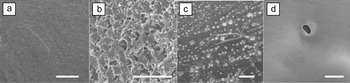
In a related study focused on morphological changes rather than chemical transformations, researchers used ex situ scanning electron microscopy (SEM) to study clean lithium foil surfaces that had been gradually exposed to commercial battery electrolytes for various lengths of time.Reference López, Vaughey and Dees17,Reference López, Vaughey and Dees24 These studies tracked the reactivity of lithium metal as a function of time noting the evolution of species formed and morphological changes from the initial exposure through cell failure. Species initially formed from the reduction of solvents typically were followed by salt decomposition products in a manner similar to those seen in earlier UHV studies.Reference Rendek, Chottiner and Scherson18–Reference Rendek, Chottiner and Scherson20Figure 2 shows some of the morphological changes noted. Building clean Li-metal specimens into electrochemical cells allowed the researchers to differentiate between pre-cycling reactivity and morphologies that resulted from cycling, namely a gradual buildup of dendritic layers of electrodeposited lithium. In fact, electrochemical impedance studies of the layers by several groups have shown that the layers, in fact, undergo aging such that over time and exposure, as many as five separate layers can be differentiated within a cycled electrode.Reference López, Vaughey and Dees24–Reference Nishikawa, Fukunaka, Sakka, Ogata and Selman26 These mossy Li layers grow toward the other electrode until the lithium react with all of the available electrolyte or a Li dendrite electrically shorts the cell.Reference López, Vaughey and Dees24
Scanning electron microscope micrographs showing the time-dependent evolution of morphology of the solid electrolyte interphase layer on metallic lithium electrodes upon contact with the 1.2 M LiPF6/50 wt% ethylene carbonate: 50 wt% ethyl methyl carbonate (EC:EMC) electrolyte solution. (a) Bare lithium, (b) after 20 seconds of contact, (c) after 5 minutes, and (d) after 1 hour.Reference López, Vaughey and Dees17 The scale bar represents 50 microns.

The understanding of the metal electrode developed by studying these surface reactions and SEI films represents an important step to better understand the formation the SEI layer on lithium and to differentiate the materials formed on contact from those mainly formed during the cycling process. As previously noted, Li metal is thermodynamically unstable in organic electrolytes and reacts to form electrically insulating but ionically conductive interfaces. This interfacial SEI layer physically prevents direct contact between lithium and the electrolyte, making the Li metal kinetically stable in electrolytes. After years of effort, it is now accepted that a very stable SEI layer can be formed on graphitic carbon anodes when the electrolyte contains specific additives or solvents, such as ethylene carbonate (EC), that act as monomers to form stable polymers on the surface of the anode.Reference Wang, Nakamura, Ue and Balbuena27 This stability, in part, results from the low voltage polymerization pathway of the EC molecule and its high affinity to be the primary coordinating solvent for the lithium cation. As a result, the lithium cation preferentially delivers the reactive EC molecule to the interface between the anode and electrolyte at the point of desolvation and intercalation. Extending this strategy to Li metal with new electrolytes and additives to form tailored or designer SEI layers for Li anodes has not been as universally successful.Reference Aurbach, Zinigrad, Teller and Dan28
Characterization tools
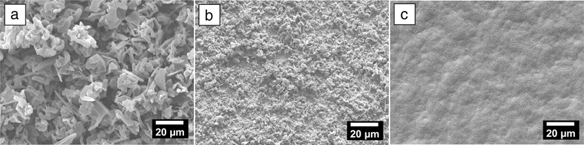
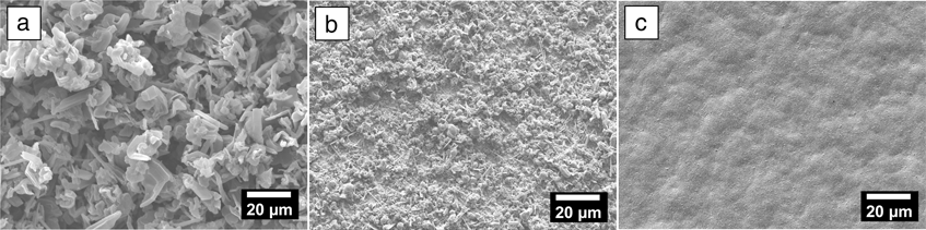
For Li-metal studies, SEM is one of the most useful techniques that can directly reveal the electrode surface morphology and help correlate that with dendritic lithium growth. Since the 1970s, it has been used extensively to analyzeReference Besenhard, Gürtler, Komenda and Paxinos29–Reference Stark, Ding and Kohl37 the effects of solvents,Reference Besenhard, Gürtler, Komenda and Paxinos29,Reference Ota, Wang and Yasukawa34,Reference Aurbach, Youngman, Gofer and Meitav38–Reference Naoi, Mori, Naruoka, Lamanna and Atanasoski40 salts,Reference Aurbach, Weissman, Zaban and Chusid30,Reference Kanamura, Tamura, Shiraishi and Takehara31,Reference Yang, Smith, Patrissi, Schumacher and Lucht41 additives,Reference Shiraishi, Kanamura and Takehara33,Reference Fujieda, Yamamoto, Saito, Ishibashi, Honjo, Koike, Wakabayashi and Higuchi42–Reference Lee, Seo, Lee, Lee, Cho and Park45 and other treatmentsReference Stark, Ding and Kohl37,Reference Yoon, Lee, Kim and Sohn46,Reference Liebenow and Luhder47 during the deposition and stripping processes. For example, it has been demonstrated that the addition of small amounts of the larger alkali metal cations to the Li-battery electrolyte has a dramatic effect on the Li-metal surface morphology on cycling. These additive cations do not reduce at these concentrations, as they exhibit an effective reduction potential below the standard reduction potential of Li ions. In solution, they are drawn to the areas of highest charge on the anode, the places where Li-surface inhomogeneities are just starting to form and act to level out the local charge, thus minimizing a driving force for the eventual formation of mossy or dendritic lithium deposits.Reference Xu, Wang, Ding, Chen, Nasybulin, Zhang and Zhang12Figure 3 shows SEM images of deposited Li films on copper substrates with different concentrations of Cs cations present in the electrolyte. In the control electrolyte, 1M LiPF6 in propylene carbonate (PC) without the CsPF6 additive, Li dendrite formation is clearly observed in the deposited Li film (see Figure 3a). Even at very low Cs+ concentrations (0.005 M), Li dendrite formation significantly decreased (Figure 3b). When the Cs+ concentration is increased to 0.05 M, the dendrite formation is completely eliminated, resulting in a very distinct improvement in overall surface morphology (Figure 3c).Reference Xu, Wang, Ding, Chen, Nasybulin, Zhang and Zhang12
Scanning electron microscope images of the morphologies of Li films deposited in an electrolyte of 1 M LiPF6/propylene carbonate with CsPF6 concentrations of: (a) 0 M, (b) 0.005 M, and (c) 0.05 M at a current density of 0.1 mA cm–2. Note the surface morphology becomes smoother with increasing Cs+ content. The effect is only seen at these low concentration levels where the effective reduction potential is below the standard lithium cation reduction potential.Reference Ding, Xu, Graff, Zhang, Sushko, Chen, Shao, Engelhard, Nie, Xiao, Liu, Sushko, Liu and Zhang57
To better understand the actual chemical species implicated in SEI formation, various techniques have been utilized. The most common diagnostic tools include Fourier transform infrared (organic species), Raman (organic species), nuclear magnetic resonance (NMR) (inorganic/organic), x-ray photoelectron spectroscopy (inorganic species), and energy-dispersive spectroscopy (inorganic species). These studies, reviewed previously in more detail, have shown that that the major species on Li-metal surfaces include Li2O, LiOH, LiF, Li2CO3, and various lithium alkyl-carbonates (RCOOLi; R = alkyl).Reference Besenhard, Gürtler, Komenda and Paxinos29–Reference Christensen and Newman48 Knowing the species as a baseline representation of the surface species allows better tracking of the degradation products of additives and alternative electrolytes. Among these, NMR is a powerful tool for detecting chemical bonds or atomic surroundings and can be very specific for isolating the species that contain lithium cations or can inform researchers about the deposition properties of the metal. Recently, Bhattacharyya et al. used the difference between the NMR signal intensities and knowledge of the penetration depth of their signal to differentiate bulk and porous lithium species and identify in situ Li dendrite growth.Reference Bhattacharyya, Key, Chen, Best, Hollenkamp and Grey49 They then successfully used this method as an in situ tool to quantitatively observe the formation of Li dendrites in different electrolytes and correlate electrochemical and solvent properties. Tying together these well-established and emerging characterization tools allows for new insights into Li-metal-based storage systems and for advances to be made in the search for new high-capacity systems.
Surface bonded protective coatings
Recent advances have highlighted new approaches for stabilizing Li metal in the presence of liquid electrolytes. Whereas previous efforts focused on producing a coating layer on top of the metallic surface by methods that included in situ polymerization of an electrolyte soluble monomer, in situ formation of Zintl salts, and direct deposition of thin polymer layers onto the surface, a more recent approach has utilized the natural hydroxyl-terminated layer of Li metal as a contact point to physically attach the protective layer to the metal surface.Reference Zinigrad, Levi, Teller, Salitra, Aurbach and Dan14–Reference Ishikawa, Machino and Morita16,Reference Li, Totir, Gofer, Wang, Chottiner and Scherson21–Reference Schmid, Bickel, Novak and Schuster23
An approach that relies on a direct chemical bond to the surface involved generating a silane-coated Li-metal surface that showed enhanced stability in Li-ion battery organic electrolytes.Reference Marchionni, Star, Menke, Buffeteau, Servant, Dunn and Wudl50 The layer, generated by the self-terminating reaction between a chloride substituent on the substituted silane and a proton from the natural OH-terminated layer on a clean Li surface, was formed on contact and was stable to the electrolyte. They noted that the coated Li metal in static systems showed lower initial impedance and slower impedance growth when compared to an uncoated control when exposed to common electrolyte solvents. An important issue identified was the need to clean the surface of the Li metal in a manner that eliminated the atmospheric passivation layer. This layer, formed during handling and storage, contains compounds generated by exposure to the atmosphere, including Li3N, Li2O, Li2CO3, and LiOH. Unless cleaned off, the nature of the reaction between the chlorosilanes and the surface species leads to silation of the contaminants, not the top layer of the Li metal. This requirement was demonstrated by using a diverse group of organosilanes, resulting in a technique to create cleaner lithium surfaces and more reproducible electrochemical cycling, as the silated passivation compounds were not attached to the surface and led to no additional protections.Reference Thompson, Schroeder, López, Neuhold and Vaughey51
Once optimized, it was shown on cycling that the silane-coated Li surfaces had two to three times the cycling lifetimes when compared to a control standard cell. These coatings, formed ex situ on the surface of the lithium before it was built into a test cell, form a packed layer on the surface of the metal. In general, the more densely packed the substituent groups off the silicon atom (R3Si-) bonded to the surface of the lithium through its oxygen termination layer, the better the cycling performance. This type of enhancement correlated well with the volume of the substituent alkyl-group, such that the best performer utilized three methyl groups, while little enhancement was seen for much larger groups (e.g., isopropyl).
Later, a second area of enhancement was noted with large R-groups attached to the silicon atom, typically ones containing aromatic phenyl groups.Reference Neuhold, Schroeder and Vaughey52 Modeling of these packed surface species indicated that while there were not as many of them bonded to the surface for steric packing reasons, their packing requirements relative to one another resulted in significant surface protection and electrochemical cycling enhancements nearly equivalent to some of the protective silanes that contained smaller alkyl groups.
A second approach to physically attaching the silane to the surface besides chloride displacement methodology is alcohol displacement. By exposing the Li metal to tetraethoxysilane (TEOS), researchers were able to create complex organo-silicon films on metal surfaces that similarly used the surface passivation layer as an anchor point.Reference Xu, Wang, Ding, Chen, Nasybulin, Zhang and Zhang12,Reference Umeda, Menke, Richard, Stamm, Wudl and Dunn53 While the layer is not self-terminating such as the chlorosilane-derived films, TEOS-derived films allow for lithium plating and stripping to occur. It was noted that during the metal electrodeposition process, lithium plated into an empty region beneath the protective layer. While these ex situ-formed protective silicon-containing layers show good adhesion to the surface, they also display uniform physical contact with the Li surface and excellent ionic conductivity in a manner similar to earlier studies on Zintl coatings.Reference Ishikawa, Machino and Morita16
These coatings, formed by the reaction of Li metal with various main group elements (e.g., Bi, Sb) rather than the terminal passivation coating, were also stable. However, their more brittle nature resulted in cracking on cycling and eventual intrusion of fresh electrolyte onto the Li-metal surface. Both approaches effectively suppress the reactions between Li metal and the non-aqueous electrolyte while they maintain their surface contacts and form. This limitation explains the stabilization of the interfacial impedance during storage, as without the movement of lithium across this interface (driven in part to the low CE), the gradual diffusion of solvents is inhibited, and parasitic reactions are held to a minimum. On cycling, however, these protective layers are gradually broken down and fail as Li electrodeposition creates new unprotected surfaces, which, once nucleated, gradually grow and create new reactive areas of the anode surface.Reference Zinigrad, Levi, Teller, Salitra, Aurbach and Dan14–Reference Ishikawa, Machino and Morita16,Reference Neuhold, Schroeder and Vaughey52
An exception to this observation was the earlier work of Aurbach et al. on 1,3 dioxolane-based electrolytes.Reference Fei, Xinguo and Yuwen54 In these systems, the solvent was also a monomer for the protective SEI layer, so any new exposure of the underlying metal surface could be “healed.” However, the polymer formed lacked the chemical stability required to work for extended periods in an electrochemical cell. In general, compared to the in situ formed SEI films (e.g., by 1,3 dioxolane), the ex situ formed films usually have more defects and are incapable of self-healing, as there is no unreacted species in the sealed cell to draw upon to repair new fissures. Although some of these surface protection schemes may offer enhanced stability for lithium anodes initially, as of yet, these protective films are too strongly affected during cycling to act as long-term solutions; however, they show promise as a methodology to act in conjunction with other materials (e.g., solid electrolytes).Reference Key, Schroeder, Ingram and Vaughey55,Reference Hubaud, Schroeder, Key, Ingram, Dogan and Vaughey56
Self-healing electrostatic shield
Recently, Ding et al. demonstrated another mechanism that could influence Li deposition preference to obtain a dendrite-free Li anode, which is called the self-healing electrostatic shield (SHES) mechanism.Reference Ding, Xu, Graff, Zhang, Sushko, Chen, Shao, Engelhard, Nie, Xiao, Liu, Sushko, Liu and Zhang57 This mechanism does not rely on the mechanical strength of a protection layer; instead, it relies on an electrostatic shield formed by electrolyte additives. At low concentrations, selected cations (such as cesium or rubidium) exhibit an effective reduction potential below the standard reduction potential of lithium ions. Thus, during lithium deposition, these additive cations form a positively charged electrostatic shield around the initial growth tip of the protuberances without reduction and deposition of the additives. Left unchecked, these protuberances eventually become the nucleation point for the growth of dendritic lithium electrodeposits. The SHES mechanism forces further deposition of lithium to adjacent regions of the anode and eliminates dendrite formation in Li-metal batteries. Once the applied electric voltage is turned off, this charged cloud will dissipate and does not form a permanent film on the lithium surface.Reference Ding, Xu, Graff, Zhang, Sushko, Chen, Shao, Engelhard, Nie, Xiao, Liu, Sushko, Liu and Zhang57
Stabilized Li-metal powder in Li-ion cells
Although the direct use of Li metal as the anode electrode has posed particular safety and battery life challenges, a new approach to using Li metal in an electrochemical cell is the direct incorporation of Li metal into a standard Li-ion battery cell design. This hybrid approach can act as a capacity and energy booster when compared to a conventional electrochemical cell and has been a major research and development target.Reference Jarvis, Lain, Gao and Yakovleva58,Reference Jarvis, Lain, Yakovleva and Gao59
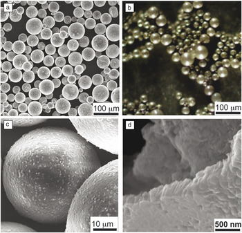
In one example, Li metal is processed into a powder form with Li2CO3 as a surface stabilization layer.Reference Xiang, Wang, Liu and Minor60 This material is produced commercially by FMC Lithium Corporation as a Li carbonate stabilized Li-metal powder (SLMP). The dense, thin protective layer provides both air and solvent stability for the underlying Li metal, which allows SLMP to be safely handled in a dry room atmosphere. An SEM image, at low magnification (Figure 4a), shows that as produced, the SLMP has varying diameters ranging from ∼5 μm to ∼50 μm. When viewed under an optical microscope (Figure 4b), the SLMP has a metallic silver metal color. As a surface coating with high adhesion, the process used to form the Li carbonate coating is continuous and shows no obvious cracks (see Figure 4c). A higher magnification SEM of the Li2CO3 layer shown in Figure 4d after the Li-metal core has been extracted indicates that the typical coating is ∼100 nm thick and robust. Analytical evaluation of the materials indicates that the typical SLMP particle is composed of 97% lithium metal by weight; the remaining 3% is composed of the Li2CO3 protective coating.Reference Xiang, Wang, Liu and Minor60–Reference Wang, Fu, Battaglia and Liu62
(a) Low magnification scanning electron microscopy (SEM) image of stabilized lithium-metal powder (SLMP) particles.Reference Xiang, Wang, Liu and Minor60 (b) Optical microscopic image of SLMP particles. Image courtesy of FMC Lithium Corporation. (c) High magnification SEM image of the SLMP.Reference Xiang, Wang, Liu and Minor60 (d) High magnification SEM image of the lithium carbonate coating layer.Reference Li and Fitch61

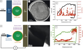
A detailed electromechanical study to determine the quality and properties of the carbonate coating was conducted on individual SLMP particles by utilizing an in situ probe technique in a real-time transmission electron microscope (TEM) experiment (Figure 5). The conductivity of the Li2CO3 shell was estimated by this technique to be ∼10–6 S/cm, where the experimental set-up is shown in Figure 5d.Reference Xiang, Wang, Liu and Minor60 Since the carbonate shell is insulating and electrodes need to have some electronic conductivity, methods to expose the underlying Li metal were deemed critical for the utilization of the SLMP powder. It was determined that a pressure of ∼15 MPa on the SLMP particle was needed to initiate the fracture of the carbonate coating and expose the Li metal, well in the range of the pressure used to reduce porosity in a typical electrode calendaring compression procedures.Reference Xiang, Wang, Liu and Minor60 Calendaring is a finishing process by which the electrode is passed under rollers at high temperatures and pressures to reach a specific electrode porosity.
Nanomechanical and electrical measurement of stabilized Li-metal powder (SLMP) under in situ transmission electron microscope observation. (a) Schematic diagram of an in situ compression and electrical test of a single SLMP particle. (b) Displacement-controlled compression of a single particle. (c) Under displacement-controlled compression, the load initially increases versus displacement, then plateaus, but the measured current versus displacement curve remains low throughout the compression. The displacement and current curves are plotted in black and red, respectively. The point of compression where the protective carbonate shell starts to fail is given by the peak load at approximately 1000 μN, just below a displacement of 2000 nm. (d) The schematic diagram of an in situ mechanical and electrical test of a single SLMP using a sharp conductive indenter tip. (e) Displacement-controlled indentation of a single particle. (f) Under displacement-controlled indentation, the load increases versus displacement. The measured current increases when the indentation tip pokes through the LiCO3 layer at ∼200 μN and a displacement of ∼1500 nm, where the metallic lithium has been accessed. The displacement and current curves are plotted in green and red, respectively.Reference Xiang, Wang, Liu and Minor60

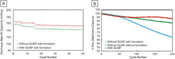
As noted before, utilizing coated powdered lithium opens up new avenues for incorporating Li metal in an electrochemical cell. In a hybrid anode cell, a typical process to use SLMP in the Li-ion battery system includes dispersion of SLMP onto graphite anode surfaces and calendaring to break the carbonate shell to expose and activate the Li metal. The Li-metal-coated graphite electrode, when used in a traditional Li-ion battery, shows significant capacity enhancements because of the additional active Li metal (Figure 6).Reference Wang, Fu, Zhang, Yuan, Amine, Battaglia and Liu63 Performance enhancements include reduction in first-cycle capacity loss (of an SLMP prelithiated cell) and a corresponding first-cycle CE improvement. Because lithium has a different SEI than graphitic carbon, SLMP-based electrodes promise to act as an alternative route to control or manipulate SEI layer formation processes. This route may offer a pathway to the potential use of other promising anode materials, such as Si and Sn, that have large first-cycle capacity losses and SEI layers more chemically similar to Li metal than graphitic carbon in the next generation of high-energy Li-ion batteries.Reference Jarvis, Lain, Gao and Yakovleva58,Reference Jarvis, Lain, Yakovleva and Gao59,Reference Wachtler, Besenhard and Winter64,Reference Forney, Ganter, Staub, Ridgley and Landi65
(a) Cycle performance for graphite/NMC (lithium nickel manganese cobalt oxide Li(Ni1/3Mn1/3Co1/3)O2) full cells with (red symbols) and without stabilized lithium-metal powder (SLMP) (green symbols) at a C/3 rate. The amount of current needed to charge a cell in one hour is referred to as the C-rate. A C/3 rate means 1/3 of that current was used, and the full charge took three hours. (b) The cell with SLMP was rested at open circuit for four days before cycling to allow it to reach equilibrium with the electrolyte. The cell without SLMP was put through a series of low rate formation cycles to allow it to build up a more stable solid electrolyte interphase layer (green symbols) and was cycled at C/25 for five cycles, followed by C/10 for 10 cycles, then cycled at a C/3 rate. The cell without SLMP and not put through formation cycling (blue symbols) was cycled at C/3 directly after assembling.Reference Wang, Fu, Zhang, Yuan, Amine, Battaglia and Liu63

Future directions
Li metal is an ideal anode for the next generation of high-capacity rechargeable batteries, including Li-air, Li-S, and other Li-based batteries using intercalation compounds. To enable broad applications of Li anodes, more fundamental studies need to be conducted to simultaneously address the two barriers discussed previously. One of the key breakthroughs may come from the development of new electrolytes (and/or additives), which can form a stable solid electrolyte interphase (SEI) layer with enough mechanical strength and flexibility to withstand repeated electrochemical cycling. This ideal electrolyte may consist of only two components: one inhibiting dendrite growth and another forming a stable SEI layer to improve Coulombic efficiency. In this review, the status of three approaches at manipulating and controlling the Li metal–electrolyte interface were discussed. While previous studies have concentrated on coatings with minimal surface connectivity, the approaches discussed—namely a coating that forms and dissipates into the electrolyte based on charge density, a coating bonded to the termination layer of lithium, and an ex situ conformal carbonate coating formed at the interface—all highlight new research directions all at different levels of development ranging from simple lab cells to pilot plant production. Although there are still many obstacles to be overcome, we are optimistic that Li metal will be used as an anode in rechargeable batteries in the foreseeable future, enabling the next generation of power sources.
Acknowledgments
J.T.V. and G.L. were supported by the Assistant Secretary for Energy Efficiency and Renewable Energy, Office of Vehicle Technology of the US Department of Energy (DOE), under the Batteries for Advanced Transportation Technologies (BATT) Program. J.G.Z. was supported by the Assistant Secretary for Energy Efficiency and Renewable Energy, Office of Vehicle Technology of the US Department of Energy (DOE), and the Laboratory Directed Research and Development fund of PNNL.