I. INTRODUCTION
Comb-line filters are widely employed in modern microwave communication systems for applications where compact sizes and good performances in terms of spurious rejection are required. However, to reach high values of end capacitance, a comb-line should be realized in a cavity by rod resonators with very small gaps from the cavity itself.
As an example, consider a resonator with fundamental resonant frequency f 1 = 4 GHz. In order that the first higher-order mode be at f 2 = 18 GHz, the gap between the resonator and the cavity must be of the order of a few tens of microns (i.e. 150 µm). It is apparent that such a value of the gap cannot be realized with an adequate degree of precision, as the standard computer numerical control (CNC) tolerances are ±25 µm. Such considerations motivated the investigation of a modified structure, allowing for higher robustness to milling tolerances, yet providing similar performances in terms of the f 2/f 1 ratio without significantly affecting the Q-factor with respect to the standard comb-line configuration [Reference Kuo and Shih1–Reference Chuma and Mirshekar-Syahkal6].
II. PROPOSED APPROACH
It is well known that a comb-line resonator is equipped with an end capacitance that can be either lumped or distributed. In the case of a rod resonator, to avoid small gaps, the end capacitance can be increased by enlarging its top head. In this way the structure obtained is a stepped-impedance coaxial resonator, whose aspect ratio can be controlled to maximize the ratio f 2/f 1. The resonator features an inductive section with radius r L and length l L plus a capacitive section with radius r C and length l C. To improve the mechanical stability and the electric contact with the shielding case the base of the resonator was enlarged below the inductive section as shown in Fig. 1.
Structure of the stepped-impedance resonator obtained in order to maximize the ratio f 2/f 1 with an enlarged base to improve the electric contact and stability.

The procedure adopted to maximize the spurious rejection can be explained with reference to Fig. 2 where f 2/f 1 versus r C/r L is reported (dashed red curve). It shows a maximum value of f 2/f 1 at r C/r L = 3.8. Figure 2 also shows f 2/f 1 versus l L/l C, for fixed r C/r L = 3.8. This latter curve shows another maximum, meaning that also l L/l C can be optimized to maximize f 2/f 1. The presence of these maxima can be explained by the presence of two higher-order modes near the fundamental one with opposite trends as r C/r L and l L/l C increase. Therefore the overall behavior shows a maximum.
The maximum of f 2/f 1 versus r C/r L (dashed red curve) is achieved for r C/r L = 3.8; the maximum f 2/f 1 versus l L/l C is achieved for l L/l C = 5.8.
The resulting resonator shows an f 2/f 1 = 4.8 and an unloaded Q-factor of 1680 considering silver as the constituting metal (conductivity of 6.1 × 10⁷ s/m).
Once an optimum aspect ratio satisfying the requirements on the spurious rejection is found, this resonator can be used as a building block to design filters. It should be noted however that the coupling between such resonators is usually very weak unless particular expedients are adopted. For instance in [Reference Hao-Hui, Rong-Chan, Yu-Ting, Young-Huang and Ming-Huei7], the coupling of stepped-impedance resonators was realized through diaphragms. The presence of apertures near the resonators, however, gives rise to unwanted higher-order modes, which concur to lower the ratio f 2/f 1. A simple but effective coupling scheme is here adopted by simply inverting the orientation of adjacent resonators. This allows high coupling values without the need of additional coupling elements. As already pointed out in [Reference Snyder8], in fact, inverted resonators in evanescent-mode filters are associated with strong coupling values. As an additional advantage, in this manner the required coupling can be designed using as free parameter only the distance between the resonators.
III. DESIGN OF A SIXTH-ORDER FILTER
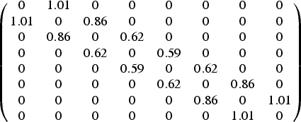
A number of N resonators of the type described in the previous section can be employed to design an N-order filter. As an example, the design of a sixth-order filter with center frequency f 0 = 4 GHz and fractional bandwidth of 4.5% is reported. It can be represented by the following coupling matrix [Reference Cameron9].
 $$\left({\matrix{ 0 & {1.01} & 0 & 0 & 0 & 0 & 0 & 0 \cr {1.01} & 0 & {0.86} & 0 & 0 & 0 & 0 & 0 \cr 0 & {0.86} & 0 & {0.62} & 0 & 0 & 0 & 0 \cr 0 & 0 & {0.62} & 0 & {0.59} & 0 & 0 & 0 \cr 0 & 0 & 0 & {0.59} & 0 & {0.62} & 0 & 0 \cr 0 & 0 & 0 & 0 & {0.62} & 0 & {0.86} & 0 \cr 0 & 0 & 0 & 0 & 0 & {0.86} & 0 & {1.01} \cr 0 & 0 & 0 & 0 & 0 & 0 & {1.01} & 0 \cr } } \right)$$
The coupling between each pair of resonators was designed with the Eigenmode analysis in HFSS® by evaluating the coupling coefficient from the magnetic and electric resonant frequencies.
As it can be seen in Fig. 3 the orientations of adjacent resonators was inverted for the reasons explained in the previous section. However the coupling that must be realized between central resonators results very weak from the coupling matrix. For this reason, it was chosen to leave these resonators equally oriented. This choice results in a more practical realization and assembly of the filter being the input and output connections at the same height. The distances that realized the desired coupling levels are d 1 = 7.78 and d 2 = 6.61 mm with reference to Fig. 3(a).
(a) Cross-section view of a sixth-order filter where the different orientations of the resonators are highlighted and (b) perspective view.
The final structure of the filter is sketched in Fig. 3, where the input and output interfaces considered are standard SMA connectors with impedance R 0 = 50 Ω.
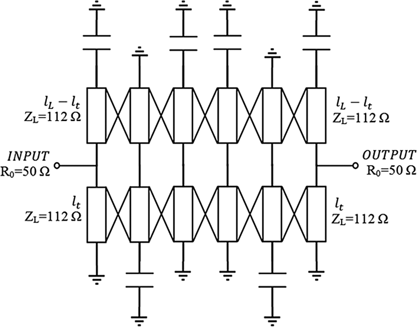
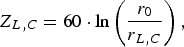
The design was carried out with the support of an electrical circuit model, based on parallel-coupled lines, shown in Fig. 4. Here the inductive section of the coaxial resonator is modeled by a high-impedance line whose value depends or r L and l L. The capacitive contribution of the gap, the capacitive section and the fringing effects are modeled by a unique lumped capacitance. The impedance associated with the high/low impedance section is that of a coaxial line, i.e.:
 $$Z_{L\comma C}=60 \cdot \ln \left({\displaystyle{{r_0 } \over {r_{L\comma C} }}} \right)\comma \;$$
where the radius of the external cavity is r 0 = 4.5 mm and r L,C is the radius of the high/low impedance line. The inductive section resulting from the previous optimization has radius r L = 0.7 mm, which corresponds to an impedance Z L = 112 Ω.
Electrical circuit model of the filter based on stepped-impedance coaxial resonators. Coupling between the resonators are modeled by parallel-coupled transmission lines while capacitive contributions are embedded in a single lumped component.
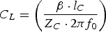
Being l C ≪ λ/4, the capacitance associated with the low-impedance section can be derived from the stepped-impedance theory in [Reference Cameron, Kudsia and Mansour10–Reference Sorrentino and Bianchi11] as
 $$C_L=\left({\displaystyle{{\beta \cdot l_C } \over {Z_C \cdot 2\pi f_0 }}} \right)$$
The input and output coupling is regulated through the distance l t between the tapping points and ground. Higher l t values result in lower couplings and vice versa.
IV. SIMULATIONS AND MEASUREMENTS RESULTS
The procedure adopted to optimize the spurious rejection of a resonator lead to the design of a filter with spurious-free band up to nearly 5 times the center frequency of the filter. In the example, considered f 0 = 4.2 GHz and the out of band response is expected to be free from unwanted resonances up to nearly 20 GHz.
Scattering parameters of the filter simulated in HFSS® are reported in Figs 5 and 6. From this simulation a Q-factor of 1500 is obtained being the insertion loss 0.5 dB at center frequency with a metal conductivity of 6.1 × 10⁷ s/m. Higher-order modes are suppressed (below −60 dB) until about 4.6 times the center frequency f 0. The measurements of the prototype showed a good agreement with the simulation, thus an insertion loss equal to 0.8 dB at center frequency, corresponding to a Q-factor of 1050.
Wide-band comparison between simulated S 21 (dashed red line) and measured (solid blue line) S 21 of the filter. The responses show a 15 GHz range free from higher-order modes.
Narrow band comparison between simulated S 11 (black dashed line) and measured S 11 (solid green line). Comparison between simulated S 21 (dashed red line) and measured S 21 (solid blue line) is also reported in detail.
The center frequency of the measured prototype (shown in Fig. 7) is 4.17 GHz, namely 0.7% lower than the simulated response. This shift can be ascribed to the insertion of tuning screws on top the cavities used to adjust the response of the filter. The graph in Fig. 8 shows the behavior of the fundamental mode resonant frequency versus the penetration length l s of a standard M1.4 screw entering within the cavity. As can be seen, the larger the penetration into the cavity, the lower the resonant frequency. This is due to the capacitive effect produced by the higher concentration of the electric field near the screw. This also explains the slight degradation of the Q-factor of the measured filter, since the screws have not been silver plated.
Manufactured prototype whose electrical measurements are reported.
Variation of the fundamental mode resonant frequency versus the penetration length of a standard M1.4 tuning screw inside the gap.
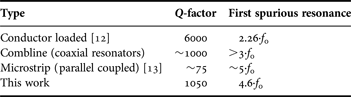
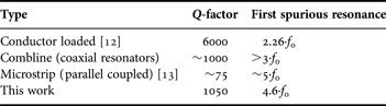
Some other approaches to wide spurious-free band filters have been proposed in the past. They showed different performances in terms of Q-factor and spurious rejection. In Table 1 a comparison of a few representative examples is provided.
Comparison between different types of filters with high spurious rejection
V. CONCLUSIONS
The use of a stepped-impedance configuration in coaxial resonators is proposed to design filters with wide rejection to spurious responses. The design of a sixth-order prototype is presented and the electrical measurements are reported confirming a high Q-factor of the filter and good performances in terms of spurious rejection, up to 4.6 times the center frequency of the filter.
Moreover, the overall structure results very compact (15 × 17 × 54 mm) and robust to typical fabrication tolerances with respect to a classic comb-line configuration with the same spurious rejection.
Future investigations will be focused on improving the near-band selectivity of the response using in-line pseudo-elliptic filters with stepped-impedance resonators.
Fabrizio Gentili was born in Foligno, Italy, in 1984. He received the Master Laurea degree (with distinction) in electronic engineering from University of Perugia, Italy, in February 2010. In 2009, he carried out his master thesis at the University of Bristol, UK, where he was involved in the design of photonic nanoantennas for THz frequencies. In March 2010, he joined RF Microtech and his work regarded mainly the design of antennas and beam forming network for array antennas. In December 2010, he passed the Ph.D. exam at the University of Perugia and started his research activity under the advice of Professor Roberto Sorrentino on RF and microwave filters. His main interests are focused on switchable filters, and innovative approaches for tunable and miniaturized filters.
Giovanni Bianchi received the Laurea degree in Electronic Engineering from the University of Rome “La Sapienza”, Rome, Italy, in 1987. In 1988, he joined the Microwave Department of Elettronica S.p.A. where he was involved in microwave components (including GaAs MMICs) and subassembly design. He joined Motorola PCS in 2000, where he worked on GSM and WCDMA mobile phone design, and in 2004 joined SDS S.r.L. where he was responsible for microwave designs. Since January 2008 he has worked as a R&D Engineer in the hardware/RF division at Verigy, and is an expert of high frequency theory and techniques. In his 23 years of design experience, he has covered both passive and active microwave components, including filters, amplifiers, oscillators, and synthesizers. He is the author of four books as well as 12 papers. With R. Sorrentino in 2010 he has co-authored the book “Microwave and RF Engineering” for John Wiley & Sons.
Luca Pelliccia was born in Foligno, Italy, in 1984. He received the Master Laurea degree (with distinction) in electronic engineering from the University of Perugia, Italy, in April 2009. In 2008–2009, he carried out his master thesis research in Ericsson AB, Mölndal (Sweden), where he was involved with the design of innovative concepts of waveguide filters for microwave applications at E-band frequencies (71–86 GHz). In May 2009, he joined the Department of Electronic and Information Engineering of the University of Perugia. His research activities include the development and design of new solutions for high-Q tunable filters, micromachined filters and miniaturized waveguide filters, and diplexers. His research involvement has resulted in the publication of several papers in the proceedings of International Microwave Conferences. In November 2012, he received his Ph.D. degree under the advice of Professor Roberto Sorrentino. He is currently working at RF Microtech (Perugia) as a microwave engineer.
Roberto Sorrentino is a Professor at the University of Perugia, Italy. His research activity deals with the analysis and design of microwave and millimeter-wave circuits and antennas. Author or co-author of more than 150 technical papers in international journals, 300 refereed conference papers and three books. Roberto Sorrentino is an IEEE Fellow (1990), recipient of the MTT-S Meritorious Service Award (1994), the IEEE Third Millennium Medal (2000), Distinguished Educator Award from IEEE MTT-S (2004). He was the Editor-in-Chief of the IEEE Microwave and Guided Wave Letters (1995–1998) and was among the founders and President of the European Microwave Association (1998–2009).