1. Introduction
The China fusion engineering test reactor (CFETR) is a tokamak-type fusion reactor, which is designed in China and fills the gap between international thermonuclear experimental reactor (ITER) and the DEMO-class reactor.
As a fusion reactor, CFETR’s components will be severely impacted in terms of their lifespan and performance due to the complex operating conditions during its operation, including extreme environments such as high temperatures, strong magnetic fields, and intense radiation. This is especially true for components that are directly exposed to the plasma, such as the first wall, blanket, diverters, and heating devices, which will be subjected to varying degrees of high-energy neutron radiation and will become irradiated and activated due to interaction with the plasma or neutrons.
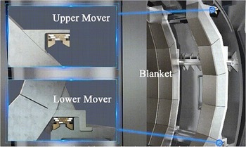
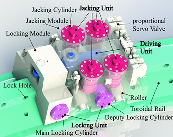
The CFETR blanket is a large and heavy module, with each module being 7.6 m tall and weighing 60 tons. In the maintenance process, the blanket is needed to transfer from the vacuum vessel (VV) to the maintenance port. The whole process is completed by blanket remote maintenance robot (BRMR). BRMR includes two Movers (as shown in Fig. 1). Each Mover consists of a driving unit, a Jacking Unit, and a locking unit, all of which are hydraulic transmission systems [Reference Li, Lu, Cheng, Zhao, Yang, Zhang, Li and Shi1]. The Mover driving unit (MDU) connects the locking module (LM) and jacking module (JM) as shown in Fig. 2. The Mover jacking unit (MJU) consists of four jacking cylinders (JC) in JM. The Mover locking unit (MLU) consists of a pair of main locking cylinders (MLC) in LM and a pair of deputy locking cylinders (DLC) in JM. In the maintenance process, firstly, JCs of MJU lift the blanket 30 mm upwards and unlock the blanket from VV. Second, pistons of DLC of MLU stretch out into the lock hole lock the JM, and blanket on the rail. Pistons of MLC of MLU retract from the lock hole to unlock the LM. Then, the driving cylinder (DC) of MDU stretches out and drives the LM move along the toroidal rail. Third, pistons of DLC of MLU retract from the lock hole to unlock the JM and blanket. Pistons of MLC of MLU stretch out into the lock hole and lock the LM. Then, the DC of MDU retracts and drives the JM and blanket move along the toroidal rail. After the repetition of the process above, the blanket can be transferred to the maintenance port. If the blanket moves in the opposite direction, vice versa. The whole synchronous movement of the blanket requires synchronous movement of the BRMR which is the synchronous movement of the upper and lower Mover. The blanket has a narrow, long structure and high gravity center, which is easy to get stuck during the toroidal movement. In the process of blanket toroidal transportation, the dynamic tracking accuracy of the displacement is required to be ±5 mm, the steady-state accuracy of the displacement is ±2 mm, and the dynamic tracking accuracy of the synchronous displacement is ±5 mm. So, synchronous movement requires high precision of pose and synchronization control of the blanket.
Schematic diagram of blanket transportation.

Mover schematic diagram.

There are many motion control algorithms, such as robust control, sliding mode control, proportional–integral–derivative (PID) control, etc. are widely used in research and factorial application [Reference Yu, He, Li, Li and Li2, Reference Yu, Li, He, Feng, Cheng and Silvestre3]. However, robust control design often tends to be conservative and control effect will decrease when the uncertainty goes beyond the specified limits [Reference Alleyne, Allgöwer, Ames, Amin, Anderson, Annaswamy, Antsaklis, Bagheri, Balakrishnan and Bamieh4]. The mostly used robust control often combines with other methods, such as adaptive method, etc., which will lead to higher controller order and lower steady state accuracy [Reference Zhu, Wang and Xie5]. Sliding mode control has chattering phenomenon. This method is often approved by changing reaching law to decrease chattering, but it may compromise control performance. PID is well known in the industry but PID control is not well-suited for systems with nonlinear dynamics, time-varying parameters, or complex behaviors. And PID controllers may have slow responses for processes with fast dynamics, as the controller may not be able to keep up with rapid changes in the process variable. These methods are not suitable for BRMR due to their characteristics.
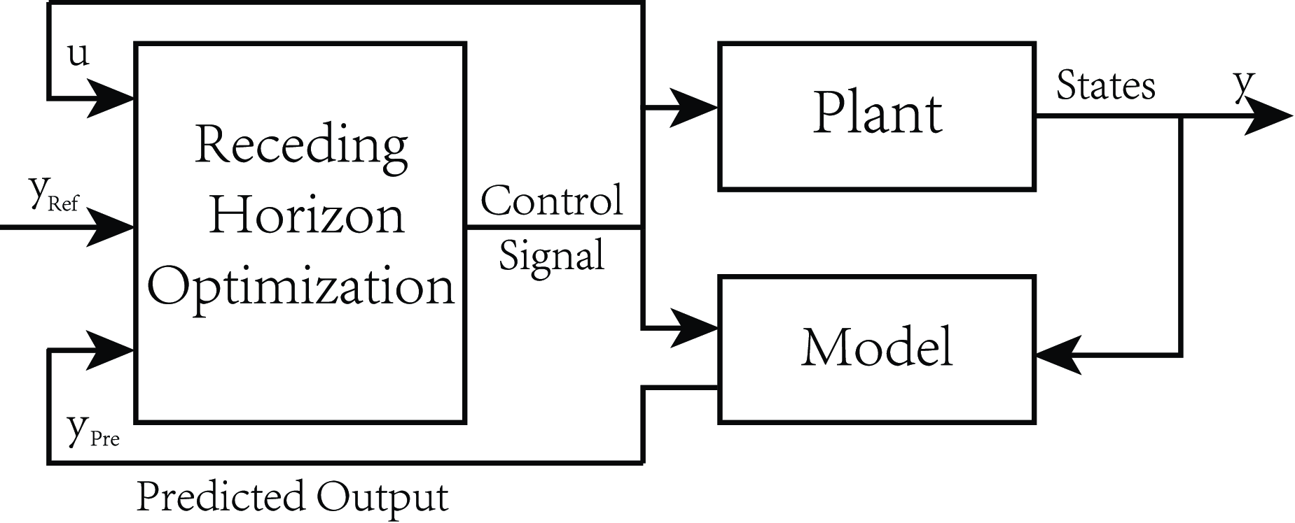
MPC schematic diagram.
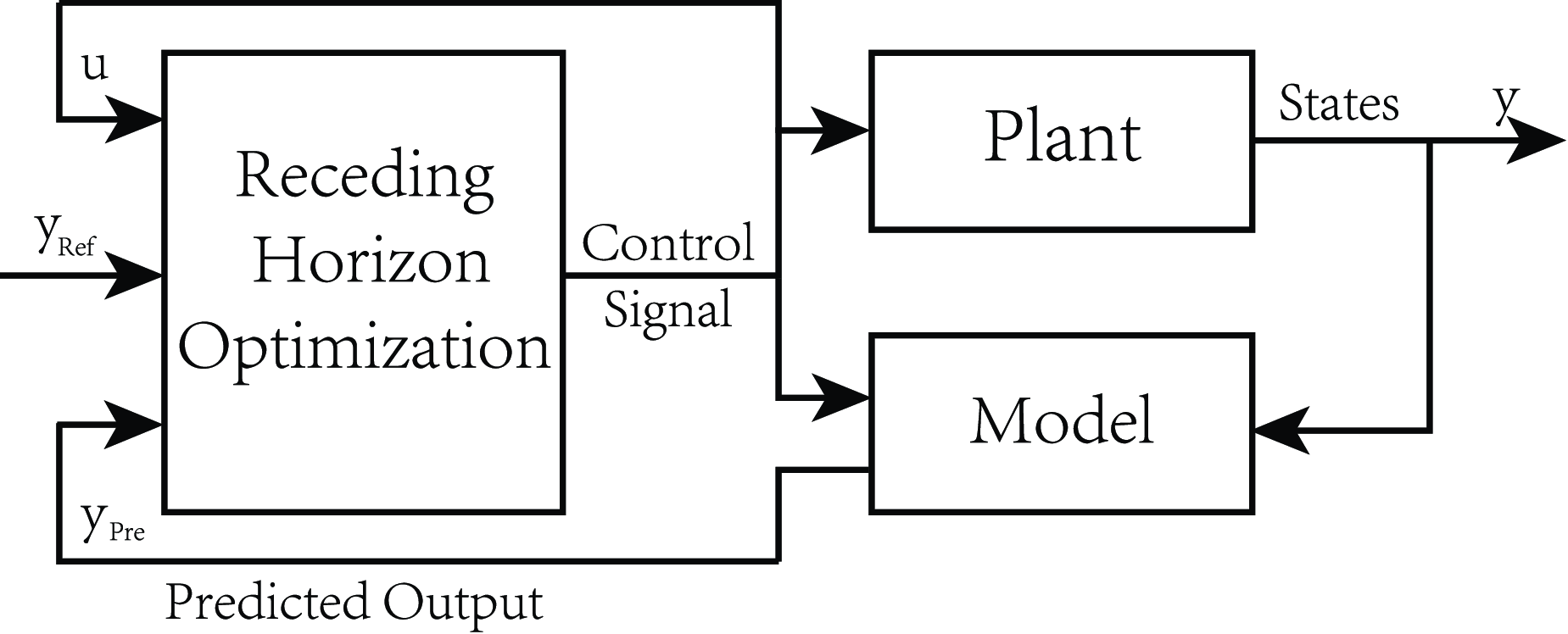
Model predictive control (MPC) is a control algorithm that uses a mathematical model of the system being controlled to make predictions about its future behavior as shown in Fig. 3. These predictions are then used to determine an optimal control action that minimizes cost function over a finite time horizon. This control algorithm can find the optimal control values repeatedly at each time step. In the actual application, it can predict system output, and do the optimization process based on the newest system prediction output and actual state feedback. MPC can handle systems with complex dynamics and multiple inputs and outputs and overcome disturbances and uncertainties in the system, as it can adjust the control action based on real-time measurements of the system’s state. It can optimize the performance of the system over a finite time horizon, leading to improved efficiency and reduced costs. MPC can also ensure safe and reliable operation in the real system based on constraints in the optimizing process [Reference Avanzini, Zanchettin and Rocco6–Reference Nascimento, Dórea and Gonçalves8]. Tiancheng Ouyang et al established a model predictive controller for heavy-duty automatic transmission shifting pressure control [Reference Ouyang, Lu, Cheng and Wang9]. The simulation results indicated that the MPC can be applied to heavy-duty vehicles for improving shift quality. Joseph T. Jose et al used MPC for the dynamic performance enhancement of an excavator boom and gained a significant reduction of cost function and vibration [Reference Jose, Das and Mishra10]. Buyoun Cho et al used MPC to improve the energy efficiency of legged robots and achieved the commanded motion while minimizing energy consumption [Reference Cho, Kim, Shin, Oh, Park and Park11]. Balint Varga et al proposed MPC in mid-sized heavy-duty vehicle manipulator systems with a hydraulic working arm and got smoother motions after the dual-trajectories optimization [Reference Varga, Meier, Schwab and Hohmann12]. Qin Shi et al and Mingming Mei et al used MPC to get better performance in pressure-demand control of electro-hydraulic braking systems [Reference Shi and He13, Reference Mei, Cheng, Mu, Pei and Li14]. Heybroek Kim et al proposed MPC in hydraulic multichamber actuator force control and got good force tracking performance [Reference Heybroek and Sjöberg15]. Xiaohua Zeng et al designed an MPC feedback controller (FMPC) to calculate the control input sequence of engine torque and hydraulic variable pump displacement [Reference Zeng, Li, Yin, Song, Li and Yang16]. Simulation results showed that the designed FMPC has the best performance, and control performance can be guaranteed in a real-time environment. Frank A. Bender et al used the MPC algorithm to control a hydraulic mini excavator and experimental results showed the developed control effect in hydraulic machinery [Reference Bender, Göltz, Bräunl and Sawodny17]. O. A. Dahunsi et al presented a controller based on neural network (NN) and MPC [Reference Dahunsi, Pedro and Nyandoro18]. Simulation results demonstrate the superior performance of the NNMPC over the generic PID based on adapting to the deterministic road disturbance. Jouko Kalmari et al presented nonlinear model predictive control (NMPC) to do the anti-sway control of a hydraulic forestry crane and results showed that it can reduce sway significantly [Reference Kalmari, Backman and Visala19].
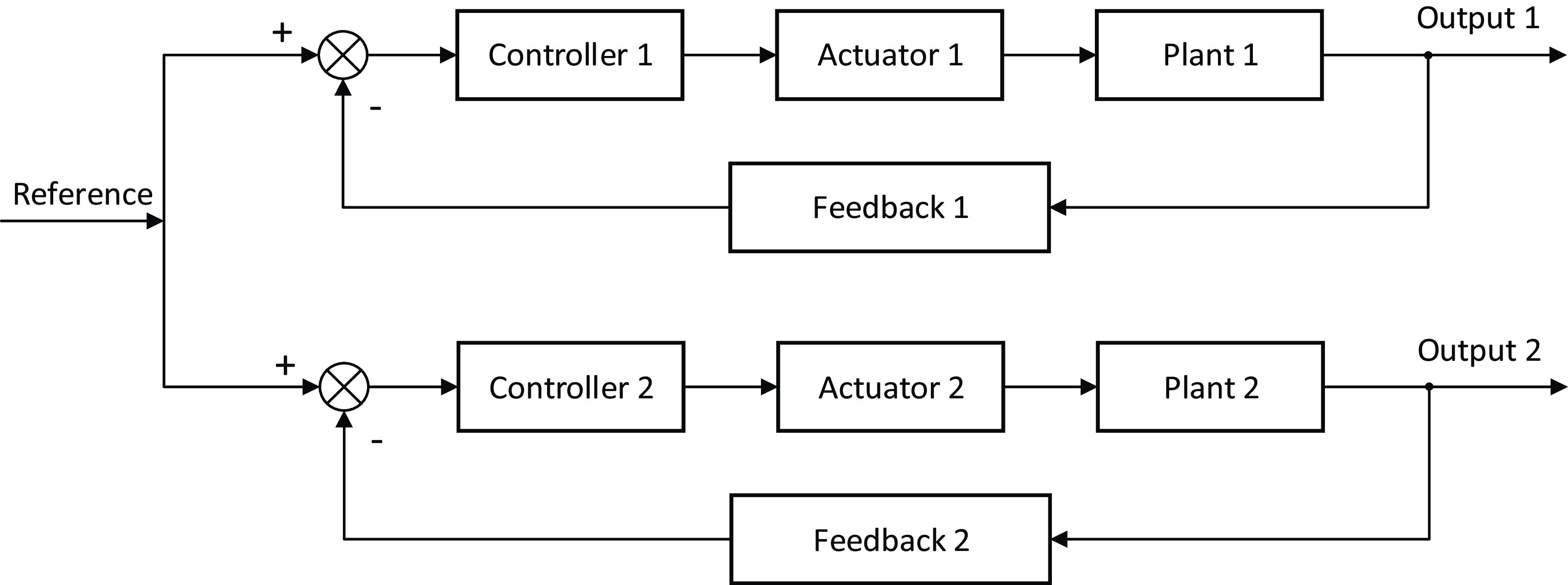
Equal control schematic diagram.

Master-slave control schematic diagram.

Cross-coupling control schematic diagram.

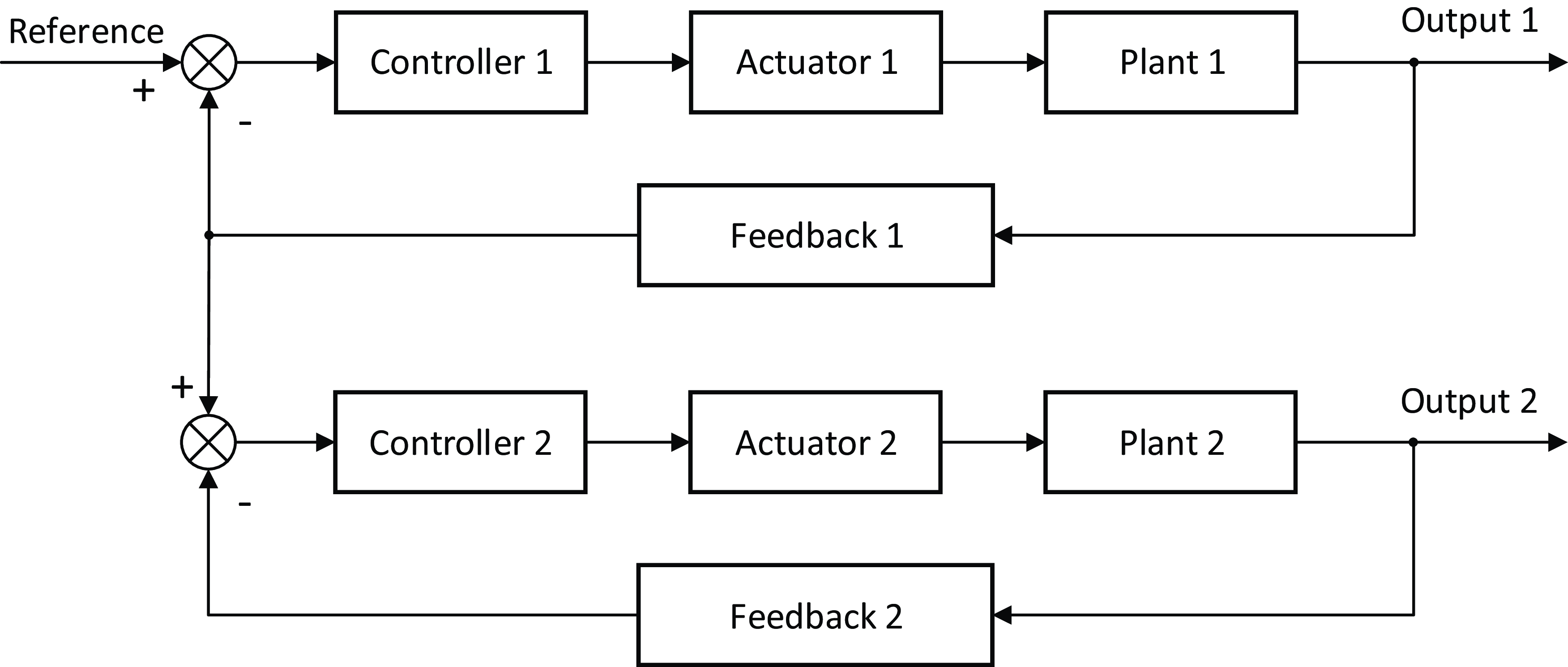
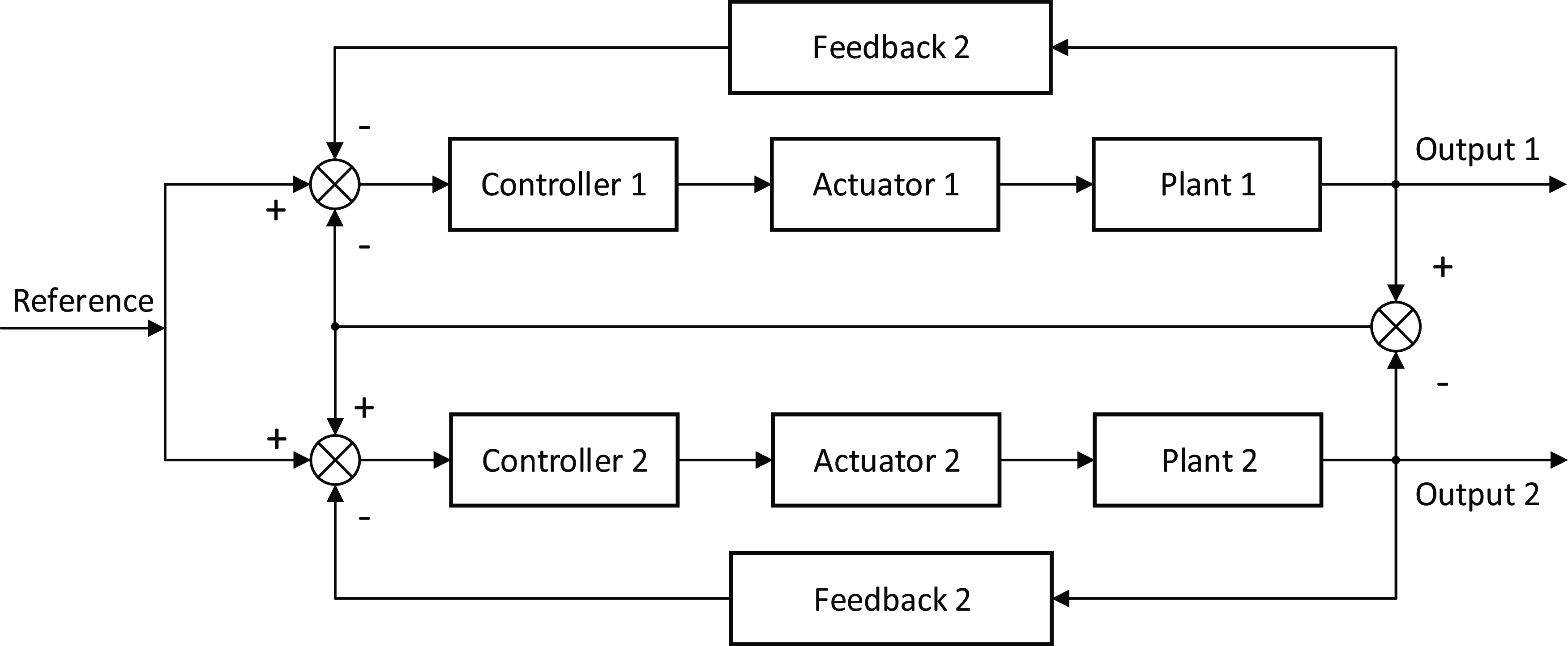
In synchronization control, there are mainly three methods: equal control, master-slave control, and cross-coupling control. In equal control, multiple hydraulic actuators simultaneously track the same ideal input signal to achieve synchronous control as shown in Fig. 4. The synchronization accuracy of equal control depends on the consistency of each hydraulic component in the hydraulic system. If the consistency of the components is good, the synchronization error will be small. However, if components have low consistency, the system has a bad synchronization effect. And this method has a weak anti-interference ability. In master-slave control, multiple hydraulic actuators track the output of one of the actuators as a standard, and the other actuators are controlled to track this standard to achieve synchronous operation as shown in Fig. 5. Without adding feedforward control, the slave hydraulic cylinder has a large tracking delay compared to the master hydraulic cylinder, resulting in a large error. In cross-coupling control (CCC), all hydraulic actuators track the same input signal, and the error between the actuators is coupled for synchronous control as shown in Fig. 6. This method can achieve convergence of trajectory and synchronization error simultaneously, ensuring synchronization accuracy without affecting the position accuracy of a single cylinder. Xinyu Yang et al proposed a finite-time tracking and cross-coupling synchronization control method for a dual-motor servo system [Reference Yang, Wang, Wang, Wang and Sial20]. Several simulations proved the controller’s stability and effectiveness. Dong Sun et al proposed a model-free cross-coupled controller for position synchronization of multiaxis motions [Reference Sun, Shao and Feng21]. Dealing with the coupled position error experiments showed the effectiveness of the controller. Hao Yuan et al used CCC method to realize the synchronous cooperation of two parallel permanent magnet linear synchronous motors [Reference Yuan and Zhao22]. Experimental results demonstrated the efficiency and superior performance of the CCC method. Zhian Kuang et al presented CCC and sliding mode control to reduce the incoordination among driving linear motors [Reference Kuang, Gao and Tomizuka23]. The simulation and experiment results proved their effectiveness and advantages over conventional methods. Guoqiang Han et al presented improved sliding mode control and CCC in the speed synchronization control of dual-switched reluctance motor and got a good performance in simulation and experiment [Reference Han, Lu, Hong, Wu, Xu and Zhu24]. Songchun Zou et al proposed CCC to enhance the synchronization performance of vehicle dual-motor steer-by-wire system and proved the effectiveness of CCC by dual-motor experiment [Reference Zou, Zhao, Wang, Liang and Chen25].
The MPC-CCC control algorithm.
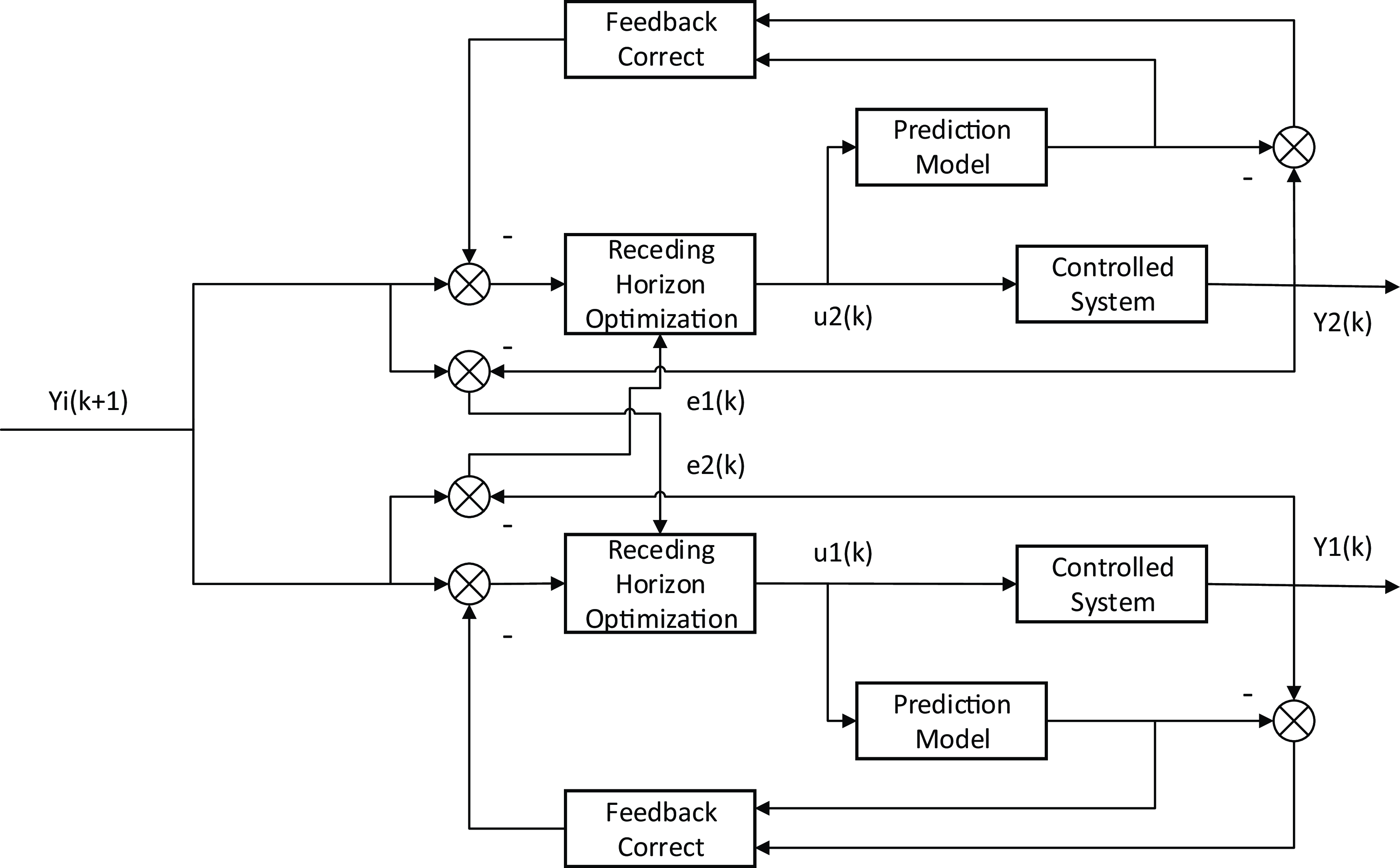
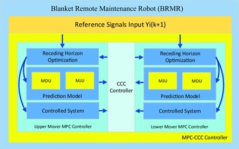
From the above studies, it is found that MPC is widely used in hydraulic systems and has good performance in actual control that improves the stability in the real process. And in synchronization control, CCC is often used in the dual motor system and has good performance of accurate synchronous control in a complex system. So, it is an innovative way to use it in the hydraulic system. In this paper, an innovative MPC-CCC control algorithm is proposed as shown in Fig. 7. To realize accurate synchronization control of BRMR and the stable and efficient transfer and maintenance of blanket, inspired by the above studies, the main contributions in this paper can be summarized as the following items:
(1) The mathematical model of BRMR with forward and backward motion models for two asymmetric cylinders is derived based on the physical-based method which can also be used in other same type synchronization hydraulic systems. It is applied to BRMR to provide a model basis for synchronous controller design.
(2) The innovative MPC-CCC control method corresponding controller is proposed based and improved by MPC algorithm and CCC algorithm in this paper. MPC can realize a good control effect in complex system which is one of the control algorithms that can be well used in real system. And it also has good control effects in single Mover. To solve the synchronization control problem of BRMR, we extracted the synchronous errors of BRMR in controller’s cost function to decrease synchronous errors and give compensations to each single Mover in the circumstance of ensuring each single Mover system control accuracy. It is a new attempt and an effective way to deal with the high accuracy synchronization control of BRMR with the real-time hydraulic system. And the optimization equation is derived to a standard QP equation to speed up the solving process. The qpSWIFT is a light-weight real-time sparse quadratic program solver [26]. It can decrease the solving time, is faster compare to other QP solvers [Reference Pandala, Ding and Park27], and is then applied in this paper.
(3) The simulation and experiments of heteromorphic (MJU-MDY) and isomorphic (MJU-MJY) hydraulic systems are carried out to verify the control effect of MPC-CCC algorithm. The controller feasibility and stability is also verified in the real operation. In the comparison with Mover’s original PI controller, the experimental results fully demonstrate the effectiveness of this MPC-CCC control strategy on matter heteromorphic and isomorphic systems, providing theoretical and experimental experience for the successful operation of fusion reactors in the future.
The remainder of this paper is organized as follows. The BRMR modeling is shown in Section 2. The MPC-CCC controller design is shown in Section 3. Simulation analysis of BRMR with heteromorphic and isomorphic systems is shown in Section 4. Experimental results of the proposed controller compared with original PI controller accordance to Section 4 is shown in Section 5. The conclusion is found in Section 6.
2. BRMR modeling
2.1. Simplified model of the proportional servo valve
The proportional servo valve in BRMR includes an internal closed-loop control system that regulates the relationship between the input signal
 $u$
and the output valve spool displacement
 $x_{v}$
. As a result, the proportional servo valve module can be represented by the following simplified linear equation:
 \begin{equation}x_{v}=K_{1}u\end{equation}
where
 $X_{v}-$
The spool displacement;
 $K_{1}-$
The gain;
 $u-$
The input signal.
2.2. Valve-controlled asymmetric hydraulic cylinder modeling
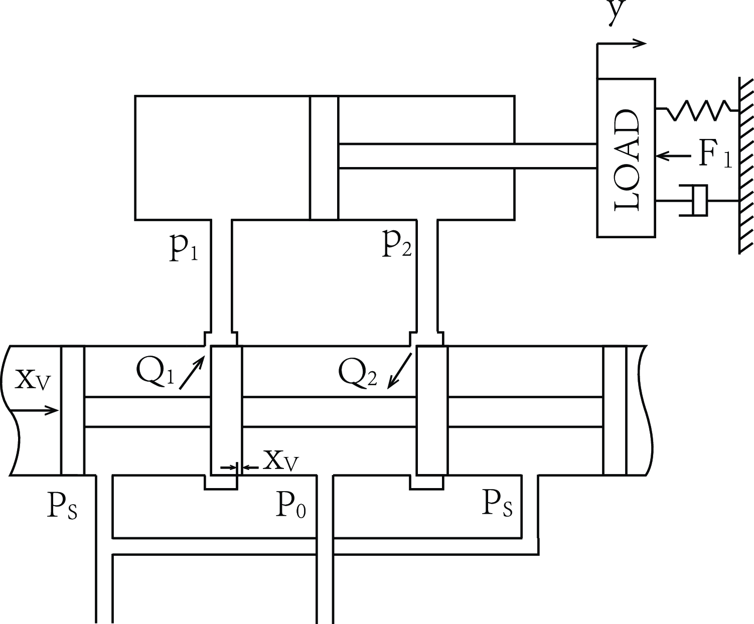
As the effective areas of the two cavities of the asymmetric hydraulic cylinder are different, it is necessary to establish piecewise linear models for both forward and backward movements of the hydraulic cylinder as shown in Fig. 8. Positive and negative values of
 $X_{v}$
represent forward and backward movements of the hydraulic cylinder, respectively. By doing so, a complete and general valve-controlled asymmetric hydraulic cylinder model can be established.
Schematic diagram of valve-controlled asymmetric hydraulic cylinder.

2.2.1.
 $\boldsymbol{x}_{\boldsymbol{v}}\gt \boldsymbol{0}$
asymmetric hydraulic cylinder model

At the beginning, the following definitions are obtained:
 \begin{equation}\textrm{n}=A_{2}/A_{1}\end{equation}
 \begin{equation}P_{L}=P_{1}-nP_{2}\end{equation}
where
 $A_{1}-$
Piston effective area with rodless cavity;
 $A_{2}-$
Piston effective area with rod cavity;
 $P_{L}-$
Load pressure;
 $P_{1}-$
Pressure with rodless cavity;
 $P_{2}-$
Pressure with rod cavity;
From Eqs. (2)–(3) and valve flow equation, the flow with load equation is derived:
 \begin{equation}Q_{L}=A_{1}\dot{y}+C_{ief}P_{L}-C_{eef}P_{s}+\frac{V_{tf}}{\beta _{e}}\dot{P_{L}}\end{equation}
where
 $y-$
Hydraulic cylinder piston displacement
 $V_{tf}-$
Effective volume;
 $C_{ief}-$
Equivalent leakage coefficient;
 $C_{eef}-$
Additional leakage coefficient.
With linearizing flow with load equation near the balance point of the valve spool [Reference Li, Lu, Cheng, Zhao, Yang, Zhang, Li and Wu28], the following equation is obtained:
 \begin{equation}Q_{L}=K_{qf}x_{v}-K_{cf}P_{L}\end{equation}
where
 $K_{qf}-$
The flow gain;
 $K_{cf}-$
Flow-pressure coefficient.
Then, the hydraulic cylinder force equilibrium equation is shown below.
 \begin{equation}A_{1}P_{L}=M\ddot{\textrm{y}}+B_{p}\dot{y}+Ky+F_{l}\end{equation}
where
 $M-$
Total piston and load mass;
 $B_{p}-$
Viscous damping coefficient of piston and load;
 $K-$
Load elastic stiffness;
 $F_{l}-$
The external force.
By combining Eqs. (1) and (5)–(6), the following equations are obtained:
 \begin{equation}\dot{\boldsymbol{x}}=\boldsymbol{A}_{\boldsymbol{f}}\boldsymbol{x}+\boldsymbol{B}_{\boldsymbol{f}}u+\boldsymbol{d}_{\boldsymbol{f}}\end{equation}
 \begin{equation}\boldsymbol{y}=\boldsymbol{C}_{\boldsymbol{f}}\boldsymbol{x}\end{equation}
where
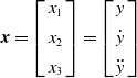 $\boldsymbol{x}=\left[\begin{array}{c} x_{1}\\[4pt] x_{2}\\[4pt] x_{3} \end{array}\right]=\left[\begin{array}{c} y\\[4pt] \dot{y}\\[4pt] \ddot{y} \end{array}\right]$
;
 $\textbf{A}_{\boldsymbol{f}}=\left[\begin{array}{c@{\quad}c@{\quad}c} 0 & 1 & 0\\[4pt] 0 & 0 & 1\\[4pt] -\dfrac{\beta _{e}C_{ief}K}{V_{tf}M} & -\left(\dfrac{K}{M}+\dfrac{\beta _{e}C_{ief}B_{p}}{V_{tf}M}+\dfrac{\beta _{e}A_{1}^{2}}{V_{tf}M}\right) & -\left(\dfrac{B_{p}}{M}+\dfrac{\beta _{e}C_{ief}}{V_{tf}}\right) \end{array}\right]$
;
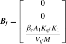 $\boldsymbol{B}_{\boldsymbol{f}}=\left[\begin{array}{c} 0\\[4pt] 0\\[4pt] \dfrac{\beta _{e}A_{1}K_{qf}K_{1}}{V_{tf}M} \end{array}\right]$
;
 $\textbf{C}_{\boldsymbol{f}}=\left[\begin{array}{c@{\quad}c@{\quad}c} 1 & 0 & 0 \end{array}\right]$
;
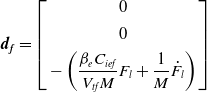 $\boldsymbol{d}_{\boldsymbol{f}}=\left[\begin{array}{c} 0\\[4pt] 0\\[4pt] -\left(\dfrac{\beta _{e}C_{ief}}{V_{tf}M}F_{l}+\dfrac{1}{M}\dot{F_{l}}\right) \end{array}\right]$
;
 $\beta _{e}-$
The effective bulk modulus of elasticity;
 $C_{ief}-$
Equivalent leakage coefficient;
 $V_{tf}-$
Effective volume;
This is the mathematical model when the hydraulic cylinder moves forward.
2.2.2.
$\boldsymbol{x}_{\boldsymbol{v}}\lt \boldsymbol{0}$
asymmetric hydraulic cylinder model

The definitions are obtained as shown in the following equations:
 \begin{equation}P_{L}=P_{2}-P_{1}/n\end{equation}
In the same way as in Section 2.2.1, the following equations are obtained:
 \begin{equation}\dot{\boldsymbol{x}}=\textbf{A}_{\boldsymbol{b}}\boldsymbol{x}+\boldsymbol{B}_{\boldsymbol{b}}u+\boldsymbol{d}_{\boldsymbol{b}}\end{equation}
 \begin{equation}\boldsymbol{y}=\textbf{C}_{\boldsymbol{b}}\boldsymbol{x}\end{equation}
where
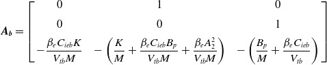 $\boldsymbol{A}_{\boldsymbol{b}}=\left[\begin{array}{c@{\quad}c@{\quad}c} 0 & 1 & 0\\[5pt] 0 & 0 & 1\\[5pt] -\dfrac{\beta _{e}C_{ieb}K}{V_{tb}M} & -\left(\dfrac{K}{M}+\dfrac{\beta _{e}C_{ieb}B_{p}}{V_{tb}M}+\dfrac{\beta _{e}A_{2}^{2}}{V_{tb}M}\right) & -\left(\dfrac{B_{p}}{M}+\dfrac{\beta _{e}C_{ieb}}{V_{tb}}\right) \end{array}\right]$
;
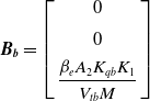 $\boldsymbol{B}_{\boldsymbol{b}}=\left[\begin{array}{c} 0\\[5pt] 0\\[5pt] \dfrac{\beta _{e}A_{2}K_{qb}K_{1}}{V_{tb}M} \end{array}\right]$
;
 $\textbf{C}_{\boldsymbol{b}}=\left[\begin{array}{c@{\quad}c@{\quad}c} 1 & 0 & 0 \end{array}\right]$
;
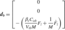 $\boldsymbol{d}_{\boldsymbol{b}}=\left[\begin{array}{c} 0\\[5pt] 0\\[5pt] -\left(\dfrac{\beta _{e}C_{ieb}}{V_{tb}M}F_{l}+\dfrac{1}{M}\dot{F_{l}}\right) \end{array}\right]$
;
 $C_{ieb}-$
Equivalent leakage;
 $V_{tb}-$
Effective volume;
 $K_{qb}-$
The flow gain.
This is the mathematical model when the hydraulic cylinder moves backward.
2.2.3. General state space model of asymmetric hydraulic cylinder
Combining the piecewise mathematical model above, the general and complete asymmetric hydraulic cylinder state space function type model can be obtained as shown in the following equations.
 \begin{equation}\dot{\boldsymbol{x}}=\boldsymbol{Ax}+\boldsymbol{B}u+\boldsymbol{d}\end{equation}
 \begin{equation}y=\boldsymbol{Cx}\end{equation}
where
 $\textbf{A}=\left[\begin{array}{c@{\quad}c@{\quad}c} 0 & 1 & 0\\ 0 & 0 & 1\\ a_{1} & a_{2} & a_{3} \end{array}\right]$
;
 $\boldsymbol{B}=\left[\begin{array}{c} 0\\ 0\\ b_{1} \end{array}\right]$
;
 $\boldsymbol{C}=\left[\begin{array}{c@{\quad}c@{\quad}c} 1 & 0 & 0 \end{array}\right]$
;
 $\boldsymbol{d}=\left[\begin{array}{c} 0\\ 0\\ d_{1} \end{array}\right]$
;
where
 $a_{1}=-\dfrac{\beta _{e}K}{M}\!\left(g_{f}\!\left(\textrm{u}\right)\dfrac{C_{ief}}{V_{tf}}+g_{b}\!\left(\textrm{u}\right)\dfrac{C_{ieb}}{V_{tb}}\right)$
;
 $a_{2}=-\left(\dfrac{K}{M}+\dfrac{\beta _{e}B_{p}}{M}\!\left(g_{f}\!\left(\textrm{u}\right)\dfrac{C_{ief}}{V_{tf}}+g_{b}\!\left(\textrm{u}\right)\dfrac{C_{ieb}}{V_{tb}}\right)+\dfrac{\beta _{e}}{M}\!\left(g_{f}\!\left(\textrm{u}\right)\dfrac{A_{1}^{2}}{V_{tf}}+g_{b}\!\left(\textrm{u}\right)\dfrac{A_{2}^{2}}{V_{tb}}\right)\right)$
;
 $a_{3}=-\left(\dfrac{B_{p}}{M}+\beta _{e}\!\left(g_{f}\!\left(\textrm{u}\right)\dfrac{C_{ief}}{V_{tf}}+g_{b}\!\left(\textrm{u}\right)\dfrac{C_{ieb}}{V_{tb}}\right)\right)$
;
 $b_{1}=\dfrac{\beta _{e}K_{1}}{M}\!\left(g_{f}\!\left(\textrm{u}\right)\dfrac{A_{1}K_{qf}}{V_{tf}}+g_{b}\!\left(\textrm{u}\right)\dfrac{A_{2}K_{qb}}{V_{tb}}\right)$
;
 $d_{1}=-\left(\dfrac{\beta _{e}}{M}\!\left(g_{f}\!\left(\textrm{u}\right)\dfrac{C_{ief}}{V_{tf}}+g_{b}\!\left(\textrm{u}\right)\dfrac{C_{ieb}}{V_{tb}}\right)F_{l}+\dfrac{1}{M}\dot{F_{l}}\right)$
;
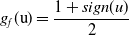 $g_{f}(\textrm{u})=\dfrac{1+sign(u)}{2}$
;
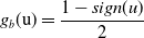 $g_{b}(\textrm{u})=\dfrac{1-sign(u)}{2}$
;
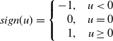 $sign(u)=\left\{\begin{array}{r@{\quad}c} -1, & u\lt 0\\ 0, & u=0\\ 1, & u\geq 0 \end{array}\right.$
.
This is the general mathematical model of the valve-controlled asymmetric hydraulic cylinder.
2.3. BRMR mathematical state space function establishment
The BRMR has two Movers. Using the general system model representation above, the MDU model of upper Mover can be obtained.
 \begin{equation}\dot{\boldsymbol{X}_{1}}=\boldsymbol{A}_{1}\boldsymbol{X}_{1}+\boldsymbol{B}_{1}u_{1}+\boldsymbol{d}_{1}\end{equation}
 \begin{equation}\dot{\boldsymbol{Y}_{1}}=\boldsymbol{C}_{1}\boldsymbol{X}_{1}\end{equation}
where
 $\boldsymbol{X}_{1}=\left(\begin{array}{c} y_{1}\\ \dot{y_{1}}\\ \ddot{y_{1}} \end{array}\right)-$
Upper Mover MDU states;
 $y_{1}$
-Upper Mover MDU displacement.
As same to Eqs. (14) and (15), the MDU model of lower Mover can be obtained.
 \begin{equation}\dot{\boldsymbol{X}_{2}}=\boldsymbol{A}_{\textbf{2}}\boldsymbol{X}_{2}+\boldsymbol{B}_{2}u_{2}+\boldsymbol{d}_{2}\end{equation}
 \begin{equation}\dot{\boldsymbol{Y}_{2}}=\boldsymbol{C}_{2}\boldsymbol{X}_{2}\end{equation}
where
 $\boldsymbol{X}_{2}=\left(\begin{array}{c} y_{2}\\ \dot{y_{2}}\\ \ddot{y_{2}} \end{array}\right)-$
lower Mover MDU states;
 $y_{2}-$
lower Mover MDU displacement.
For the convenience of establishing the controller, the two Movers are considered as a single entity. The BRMR entire system mathematical state space function is established as follows:
 \begin{equation}\dot{\mathbb{X}}=\mathbb{AX}+\mathbb{BU}+ \unicode{x1D555} \end{equation}
 \begin{equation}\mathbb{Y}=\mathbb{CX}\end{equation}
where
 $\mathbb{X}=\left(\begin{array}{c} \boldsymbol{X}_{1}\\[4pt] \boldsymbol{X}_{2} \end{array}\right)$
;
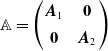 $\mathbb{A}=\left(\begin{array}{c@{\quad}c} \boldsymbol{A}_{1} & \textbf{0}\\[4pt] \textbf{0} & \boldsymbol{A}_{2} \end{array}\right)$
;
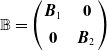 $\mathbb{B}=\left(\begin{array}{c@{\quad}c} \boldsymbol{B}_{1} & \textbf{0}\\[4pt] \textbf{0} & \boldsymbol{B}_{2} \end{array}\right)$
;
 $\mathbb{U}=\left(\begin{array}{c} u_{1}\\[4pt] u_{2} \end{array}\right)$
;
 $\unicode{x1D555}=\left(\begin{array}{c} \boldsymbol{d}_{1}\\[4pt] \boldsymbol{d}_{2} \end{array}\right)$
;
 $\mathbb{C}=\left(\begin{array}{c} \boldsymbol{C}_{1}\\[4pt] \boldsymbol{C}_{2} \end{array}\right)$
.
3. MPC-CCC controller design
Inspired by the studies in Section 1, taking advantage of MPC and CCC, the following innovative MPC-CCC is improved in this paper (see Fig. 7). The diagram of the MPC-CCC controller in BRMR is shown in Fig. 9.
The MPC-CCC controller in BRMR.

3.1. System prediction output
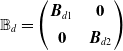
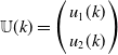
The sampling period of the Mover controller is 10 ms. The systems Eqs. (18)–(19) are transformed into the form of discrete state space functions (Eqs. (20)–(21)). Since the external force changes slowly, it is simplified to a known constant. The converted system equations are then obtained as follows:
 \begin{equation}\mathbb{X}(\textrm{k}+1)=\mathbb{A}_{\boldsymbol{d}}\mathbb{X}(\textrm{k})+\mathbb{B}_{\boldsymbol{d}}\mathbb{U}(\textrm{k})+\unicode{x1D555}_{\boldsymbol{d}}\end{equation}
 \begin{equation}\mathbb{Y}(\textrm{k})=\mathbb{C}_{d}\mathbb{X}(\textrm{k})\end{equation}
where
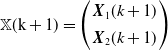 $\mathbb{X}(\textrm{k}+1)=\left(\begin{array}{c} \boldsymbol{X}_{1}(k+1)\\[4pt] \boldsymbol{X}_{2}(k+1) \end{array}\right)$
;
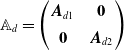 $\mathbb{A}_{d}=\left(\begin{array}{c@{\quad}c} \boldsymbol{A}_{d1} & \textbf{0}\\[4pt] \textbf{0} & \boldsymbol{A}_{d2} \end{array}\right)$
;
 $\mathbb{B}_{d}=\left(\begin{array}{c@{\quad}c} \boldsymbol{B}_{d1} & \textbf{0}\\[4pt] \textbf{0} & \boldsymbol{B}_{d2} \end{array}\right)$
;
 $\mathbb{U}(k)=\left(\begin{array}{c} u_{1}(k)\\[4pt] u_{2}(k) \end{array}\right)$
;
 $\unicode{x1D555}_{d}=\left(\begin{array}{c} \boldsymbol{d}_{d1}\\[4pt] \boldsymbol{d}_{d2} \end{array}\right)$
.
 $\mathbb{C}_{d}=\left(\begin{array}{c} \boldsymbol{C}_{d1}\\[4pt] \boldsymbol{C}_{d2} \end{array}\right)$
.
where
 $\textbf{A}_{d}$
,
 $\boldsymbol{B}_{d}$
,
 $\boldsymbol{d}_{d}$
, and
 $\textbf{C}_{d}$
are discrete forms of
 $\boldsymbol{A}$
,
 $\boldsymbol{B}$
,
 $\boldsymbol{d}$
,
 $\boldsymbol{C}$
, respectively.
According to Eqs. (20)–(21), system states for the subsequent
 $N_{p}$
sample points are predicted by the following equation:
 \begin{align} \begin{array}{c} \mathbb{X}\!\left(\textrm{k}+1|\textrm{k}\right)=\mathbb{A}_{d}\mathbb{X}\!\left(\textrm{k}\right)+\mathbb{B}_{d}\mathbb{U}\!\left(\textrm{k}\right)+\unicode{x1D555}_{d}\\ \mathbb{X}\!\left(\textrm{k}+2|\textrm{k}\right)=\mathbb{A}_{d}^{2}\mathbb{X}\!\left(\textrm{k}\right)+\mathbb{A}_{d}\mathbb{B}_{d}\mathbb{U}\!\left(\textrm{k}\right)+\mathbb{B}_{d}\mathbb{U}\!\left(\textrm{k}+1\right)+\mathbb{A}_{d}\unicode{x1D555}_{d}+\unicode{x1D555}_{d} \\ \vdots \\ \mathbb{X}\!\left(\textrm{k}+N_{p}|\textrm{k}\right)=\mathbb{A}_{d}^{N_{p}}\mathbb{X}\!\left(\textrm{k}\right)+\mathbb{A}_{d}^{N_{p}-1}\mathbb{B}_{d}\mathbb{U}\!\left(\textrm{k}\right)+\cdots +\mathbb{A}_{d}^{N_{p}-N_{c}}\mathbb{B}_{d}\mathbb{U}\!\left(\textrm{k}+N_{c}-1\right)+\mathbb{A}_{d}^{N_{p}-1}\unicode{x1D555}_{d}+\cdots +\mathbb{A}_{d}^{N_{p}-N_{c}}\unicode{x1D555}_{d}\end{array} \end{align}
Eq. (22) can be transformed to matrix type:
 \begin{align}\left(\begin{array}{c} \begin{array}{c} \mathbb{X}\!\left(\textrm{k}+1|\textrm{k}\right)\\[2pt] \mathbb{X}\!\left(\textrm{k}+2|\textrm{k}\right) \end{array}\\[2pt] \begin{array}{c} \vdots \\[2pt] \mathbb{X}\!\left(\textrm{k}+N_{p}|\textrm{k}\right) \end{array} \end{array}\right) & =\left(\begin{array}{c} \begin{array}{c} \mathbb{A}_{d}\\[2pt] \mathbb{A}_{d}^{2} \end{array}\\[2pt] \begin{array}{c} \vdots \\[2pt] \mathbb{A}_{d}^{N_{p}} \end{array} \end{array}\right)\mathbb{X}\!\left(\textrm{k}\right)+\left(\begin{array}{c@{\quad}c@{\quad}c} \mathbb{B}_{d} & \cdots & 0\\[2pt] \vdots & \ddots & \vdots \\[2pt] \mathbb{A}_{d}^{N_{p}-1}\mathbb{B}_{d} & \cdots & \mathbb{A}_{d}^{N_{p}-N_{c}}\mathbb{B}_{d} \end{array}\right)\left(\begin{array}{c} \begin{array}{c} \mathbb{U}\!\left(\textrm{k}\right)\\[2pt] \mathbb{U}\!\left(\textrm{k}+1\right) \end{array}\\[2pt] \begin{array}{c} \vdots \\[2pt] \mathbb{U}\!\left(\textrm{k}+N_{c}-1\right) \end{array} \end{array}\right)\nonumber\\[6pt]& +\left(\begin{array}{c@{\quad}c@{\quad}c} \unicode{x1D555}_{d} & \cdots & 0\\[2pt] \vdots & \ddots & \vdots \\[2pt] \mathbb{A}_{d}^{N_{p}-1}\unicode{x1D555}_{d} & \cdots & \mathbb{A}_{d}^{N_{p}-N_{c}}\unicode{x1D555}_{d} \end{array}\right)\end{align}
where
 $N_{p}-$
Prediction time domain;
 $N_{c}-$
Control time domain.
That is,
 \begin{equation}\boldsymbol{\boldsymbol{\mathfrak{X}}}=\boldsymbol{\Psi }\mathbb{X}\!\left(\textrm{k}\right)+\boldsymbol{\Phi }\boldsymbol{\boldsymbol{\mathfrak{U}}}+\boldsymbol{\boldsymbol{\mathfrak{D}}}\end{equation}
From Eq. (20), states of upper Mover and lower Mover can be obtained.
 \begin{equation}\boldsymbol{X}_{1}\!\left(k+1\right)=\boldsymbol{K}_{\textbf{1}}\mathbb{X}(\textrm{k}+1)\end{equation}
 \begin{equation}\boldsymbol{X}_{2}\!\left(k+1\right)=\boldsymbol{K}_{\textbf{2}}\mathbb{X}(\textrm{k}+1)\end{equation}
where
 $\boldsymbol{K}_{\textbf{1}}=\left(\begin{array}{c@{\quad}c} \boldsymbol{I}_{(3\times 3)} & \textbf{0}_{(3\times 3)} \end{array}\right)$
;
 $\boldsymbol{K}_{\textbf{2}}=\left(\begin{array}{c@{\quad}c} \textbf{0}_{(3\times 3)} & \boldsymbol{I}_{(3\times 3)} \end{array}\right)$
.
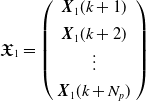
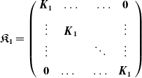
Then, the prediction states of upper Mover and lower Mover can be obtained as follows:
 \begin{equation}\boldsymbol{\mathfrak{X}}_{1}={\mathfrak{K}}_{1}\boldsymbol{\mathfrak{X}}\end{equation}
 \begin{equation}\boldsymbol{\mathfrak{X}}_{2}={\mathfrak{K}}_{2}\boldsymbol{\mathfrak{X}}\end{equation}
where
 $\boldsymbol{\mathfrak{X}}_{1}=\left(\begin{array}{c} \begin{array}{c} \boldsymbol{X}_{1}(k+1)\\[4pt] \boldsymbol{X}_{1}(k+2) \end{array}\\[4pt] \begin{array}{c} \vdots \\[4pt] \boldsymbol{X}_{1}(k+N_{p}) \end{array} \end{array}\right)$
;
 $\boldsymbol{\mathfrak{K}}_{\textbf{1}}=\left(\begin{array}{c@{\quad}c} \begin{array}{c@{\quad}c} \boldsymbol{K}_{\textbf{1}} & \ldots \\[4pt] \vdots & \boldsymbol{K}_{\textbf{1}} \end{array} & \begin{array}{c@{\quad}c} \ldots & \textbf{0}\\[4pt] & \vdots \end{array}\\[4pt] \begin{array}{c@{\quad}c} \vdots & \\[4pt] \textbf{0} & \ldots \end{array} & \begin{array}{c@{\quad}c} \ddots & \vdots \\[4pt] \ldots & \boldsymbol{K}_{\textbf{1}} \end{array} \end{array}\right)$
;
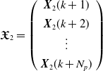 $\boldsymbol{\mathfrak{X}}_{2}=\left(\begin{array}{c} \begin{array}{c} \boldsymbol{X}_{2}(k+1)\\[4pt] \boldsymbol{X}_{2}(k+2) \end{array}\\[4pt] \begin{array}{c} \vdots \\[4pt] \boldsymbol{X}_{2}(k+N_{p}) \end{array} \end{array}\right)$
;
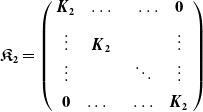 $\boldsymbol{\mathfrak{K}}_{\textbf{2}}=\left(\begin{array}{c@{\quad}c} \begin{array}{c@{\quad}c} \boldsymbol{K}_{\textbf{2}} & \ldots \\[4pt] \vdots & \boldsymbol{K}_{\textbf{2}} \end{array} & \begin{array}{c@{\quad}c} \ldots & \textbf{0}\\[4pt] & \vdots \end{array}\\[4pt] \begin{array}{c@{\quad}c} \vdots & \\[4pt] \textbf{0} & \ldots \end{array} & \begin{array}{c@{\quad}c} \ddots & \vdots \\[4pt] \ldots & \boldsymbol{K}_{\textbf{2}} \end{array} \end{array}\right)$
.
3.2. Cost function of ordinary MPC
First, in actual system, the control value
 $\mathbb{U}$
have limitation. So, it is important to limit the calculation value of
 $\mathbb{U}$
.
 \begin{equation}\boldsymbol{\mathfrak{U}}_{\boldsymbol{min}}\leq \boldsymbol{\mathfrak{U}}\leq \boldsymbol{\mathfrak{U}}_{\boldsymbol{max}}\end{equation}
Then, Eq. (29) can be turned to standard constraint in MPC.
 \begin{equation}\boldsymbol{S}_{\textbf{1}}\boldsymbol{\mathfrak{U}}\leq \boldsymbol{S}_{\textbf{2}}\end{equation}
where
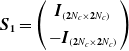 $\boldsymbol{S}_{\textbf{1}}=\left(\begin{array}{c} \boldsymbol{I}_{\left(\textbf{2}{N_{c}}\times \textbf{2}{N_{c}}\right)}\\[4pt] -\boldsymbol{I}_{\left(\textbf{2}{N_{c}}\times \textbf{2}{N_{c}}\right)} \end{array}\right)$
;
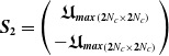 $\boldsymbol{S}_{\textbf{2}}=\left(\begin{array}{c} {\boldsymbol{\mathfrak{U}}_{\boldsymbol{max}}}_{\left(\textbf{2}{N_{c}}\times \textbf{2}{N_{c}}\right)}\\[4pt] -{\boldsymbol{\mathfrak{U}}_{\boldsymbol{max}}}_{\left(\textbf{2}{N_{c}}\times \textbf{2}{N_{c}}\right)} \end{array}\right)$
.
For ordinary MPC cost function in BRMR, it only contains the displacement error of every single MDU and the amplitude of control value of every MDU. This can be seen in the following cost function:
 \begin{equation}J_{1}=\left(\boldsymbol{\mathfrak{R}}-\boldsymbol{\mathfrak{X}}\right)^{\boldsymbol{T}}\boldsymbol{Q}_{\textbf{1}}(\boldsymbol{\mathfrak{R}}-\boldsymbol{\mathfrak{X}})+\boldsymbol{\mathfrak{U}}^{\boldsymbol{T}}\boldsymbol{Q}_{\textbf{2}}\boldsymbol{\mathfrak{U}}\end{equation}
where
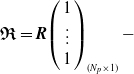 $\boldsymbol{\mathfrak{R}}=\boldsymbol{R}\!\left(\begin{array}{c} 1\\ \vdots \\ 1 \end{array}\right)_{({N_{p}}\times 1)}-$
Reference signal of BRMR;
 $\boldsymbol{R}=\left(\begin{array}{c} \boldsymbol{R}_{\textbf{1}}\\ \boldsymbol{R}_{\textbf{2}} \end{array}\right)$
;
 ${\boldsymbol{R}_{\textbf{1}}}_{(\textbf{3}\times 1)}-$
Reference signal of upper MDU;
 ${\boldsymbol{R}_{\textbf{2}}}_{(\textbf{3}\times 1)}-$
Reference signal of lower MDU;
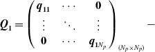 $\boldsymbol{Q}_{\textbf{1}}=\left(\begin{array}{c@{\quad}c@{\quad}c} \boldsymbol{q}_{\textbf{11}} & \cdots & \textbf{0}\\ \vdots & \ddots & \vdots \\ \textbf{0} & \cdots & \boldsymbol{q}_{\textbf{1}{N_{p}}} \end{array}\right)_{({N_{p}}\times {N_{p}})}-$
Weight matrix on the whole prediction time in displacement, velocity, and acceleration;
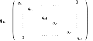 $\boldsymbol{q}_{\textbf{11}}=\left(\begin{array}{c@{\quad}c@{\quad}c} \begin{array}{c} \begin{array}{c@{\quad}c} q_{x1} & \\ & q_{v1} \end{array}\\ \begin{array}{c@{\quad}c} \vdots & \\ \vdots & \end{array}\\ \begin{array}{c@{\quad}c} & \\ 0 & \end{array} \end{array} & \begin{array}{c} \begin{array}{c@{\quad}c} \cdots & \cdots \\ & \end{array}\\ \begin{array}{c@{\quad}c} q_{a1} & \\ & q_{x2} \end{array}\\ \begin{array}{c@{\quad}c} & \\ \ldots & \ldots \end{array} \end{array} & \begin{array}{c} \begin{array}{c@{\quad}c} & 0\\ & \end{array}\\ \begin{array}{c@{\quad}c} & \vdots \\ & \vdots \end{array}\\ \begin{array}{c@{\quad}c} q_{v2} & \\ & q_{a2} \end{array} \end{array} \end{array}\right)-$
Weight matrix on the first sample time,
 $\boldsymbol{q}_{\textbf{1}{\boldsymbol{N}_{\boldsymbol{p}}}}$
is same as
 $\boldsymbol{q}_{\textbf{11}}$
;
 $q_{x1}-$
Displacement weight of upper MDU;
 $q_{v1}-$
Velocity weight of upper MDU;
 $q_{a1}-$
Acceleration weight of upper MDU;
 $q_{x2}-$
Displacement weight of lower MDU;
 $q_{v2}-$
Velocity weight of lower MDU;
 $q_{a2}-$
Acceleration weight of lower MDU;
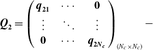 $\boldsymbol{Q}_{\textbf{2}}=\left(\begin{array}{c@{\quad}c@{\quad}c} \boldsymbol{q}_{\textbf{21}} & \cdots & \textbf{0}\\ \vdots & \ddots & \vdots \\ \textbf{0} & \cdots & \boldsymbol{q}_{\textbf{2}{\boldsymbol{N}_{\boldsymbol{c}}}} \end{array}\right)_{({N_{c}}\times {N_{c}})}-$
Weight matrix on the whole prediction time in control value;
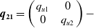 $\boldsymbol{q}_{\textbf{21}}=\left(\begin{array}{c@{\quad}c} q_{u1} & 0\\ 0 & q_{u2} \end{array}\right)-$
Weight matrix on the first sample time,
 $\boldsymbol{q}_{\textbf{2}{\boldsymbol{N}_{\boldsymbol{c}}}}$
is same as
 $\boldsymbol{q}_{\textbf{21}}$
;
 $q_{u1}-$
Control value weight of upper MDU;
 $q_{u2}-$
Control value weight of lower MDU.
3.3. Cost function of CCC algorithm
Then, considering the cross-coupled error between upper MDU and lower MDU of BRMR, the cross-coupling control algorithm is used in this paper. The cost function of cross coupled error term is shown in following equation.
 \begin{equation}J_{2}=\left(\boldsymbol{\mathfrak{X}}_{1}-\boldsymbol{\mathfrak{X}}_{2}\right)^{T}\boldsymbol{Q}_{\textbf{3}}(\boldsymbol{\mathfrak{X}}_{1}-\boldsymbol{\mathfrak{X}}_{2})\end{equation}
where
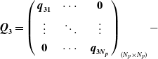 $\boldsymbol{Q}_{\textbf{3}}=\left(\begin{array}{c@{\quad}c@{\quad}c} \boldsymbol{q}_{\textbf{31}} & \cdots & \textbf{0}\\[3pt] \vdots & \ddots & \vdots \\[3pt] \textbf{0} & \cdots & \boldsymbol{q}_{\textbf{3}{\boldsymbol{N}_{\boldsymbol{p}}}} \end{array}\right)_{({N_{p}}\times {N_{p}})}-$
Weight matrix on the whole prediction time in cross-coupled displacement, velocity and acceleration;
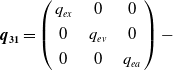 $\boldsymbol{q}_{\textbf{31}}=\left(\begin{array}{c@{\quad}c@{\quad}c} q_{ex} & 0 & 0\\[3pt] 0 & q_{ev} & 0\\[3pt] 0 & 0 & q_{ea} \end{array}\right)-$
Weight matrix on the first sample time,
 $\boldsymbol{q}_{\textbf{3}{\boldsymbol{N}_{\boldsymbol{p}}}}$
is same as
 $\boldsymbol{q}_{\textbf{31}}$
;
 $q_{ex}-$
Cross-coupled displacement weight;
 $q_{ev}-$
Cross-coupled velocity weight;
 $q_{ea}-$
Cross coupled acceleration weight.
3.4. Cost function of MPC-CCC algorithm and its optimization type
Then, combining Eqs. (31)–(32), the overall cost function of MPC-CCC controller of BRMR is obtained in Eq. (33).
 \begin{equation}J=J_{1}+J_{2}\end{equation}
By the substitution of Eqs. (23)–(24), (27)–(28), and (30)–(32) into Eq. (33), the above equation is simplified as follows optimization type:
 \begin{equation}\min J=\frac{1}{2}\boldsymbol{\mathfrak{U}}^{\boldsymbol{T}}\boldsymbol{E}\boldsymbol{\mathfrak{U}}+\boldsymbol{\mathfrak{U}}^{\boldsymbol{T}}\boldsymbol{F}\end{equation}
 \begin{equation*} s.t.\ \boldsymbol{S}_{\textbf{1}}\boldsymbol{\mathfrak{U}}\leq \boldsymbol{S}_{\textbf{2}} \end{equation*}
where
 $\boldsymbol{E}=\boldsymbol{\Phi }^{\boldsymbol{T}}\boldsymbol{Q}_{\textbf{4}}\boldsymbol{\Phi }+\boldsymbol{Q}_{\textbf{2}}$
;
 $\boldsymbol{F}=\boldsymbol{\Phi }^{\boldsymbol{T}}\boldsymbol{Q}_{\textbf{4}}\boldsymbol{\Psi }\mathbb{X}(\textrm{k})+\boldsymbol{\Phi }^{\boldsymbol{T}}\boldsymbol{Q}_{\textbf{4}}\boldsymbol{\mathfrak{D}}-\boldsymbol{\Phi }^{\boldsymbol{T}}\boldsymbol{Q}_{\textbf{1}}\boldsymbol{\mathfrak{R}}$
.
 $\boldsymbol{Q}_{\textbf{4}}=\boldsymbol{Q}_{\textbf{1}}+\boldsymbol{\mathfrak{K}}_{\textbf{3}}^{\boldsymbol{T}}\boldsymbol{Q}_{\textbf{3}}\boldsymbol{\mathfrak{K}}_{\textbf{3}}$
;
 $\boldsymbol{\mathfrak{K}}_{\textbf{3}}=\boldsymbol{\mathfrak{K}}_{\textbf{1}}-\boldsymbol{\mathfrak{K}}_{\textbf{2}}$
.
After solving the Eq. (34), the input control signal of upper MDU is the first value of
 $\boldsymbol{\mathfrak{U}}$
, and the input control signal of lower MDU is the second value of
 $\boldsymbol{\mathfrak{U}}$
.
4. Simulation analysis
In order to verify the control effectiveness of MPC-CCC controller, because the BRMR is under construction, simulations in heteromorphic (MJU-MDY) and isomorphic (MJU-MJY) circumstances of Mover mockup were implemented.
4.1. Lift cylinder of MJU and driving cylinder of MDU synchronization control simulation
The simulation was performed using MATLAB/Simulink software, with a BRMR dynamic system model that represents the process under control. The system is subject to reference signal changes, and the controllers were designed to regulate the system outputs to follow the desired set points then the effectiveness of MPC-CCC controller and PI controller can be obtained.
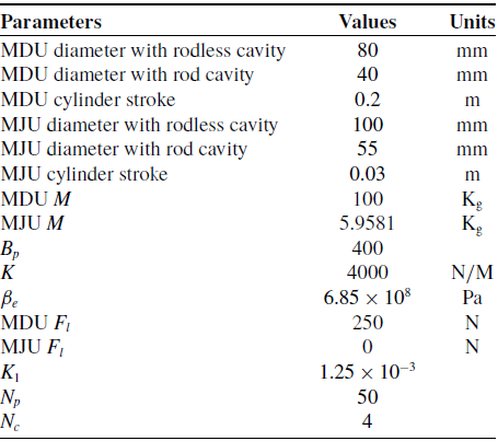
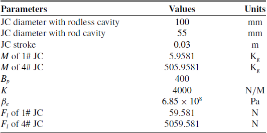
The whole simulation time is set to 20 s, the sample time is 0.01 s, which is identical to experiments. The key simulation parameters are shown in Table I.
Key simulation parameters.

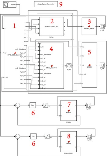
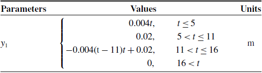
On the basement of Eq. (34), MPC-CCC and PI controller simulation platforms were built in Simulink, as shown in Fig. 10. Then, the reference signal is set up as shown in Table II.
Simulation platform for MPC-CCC and PI controllers 1-MPC-CCC controller; 2-qpSWIFT; 3-Control value extractor; 4-State observer; 5-BRMR; 6-PI controller; 7-MJU; and 8-MJU/MDU.

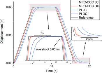
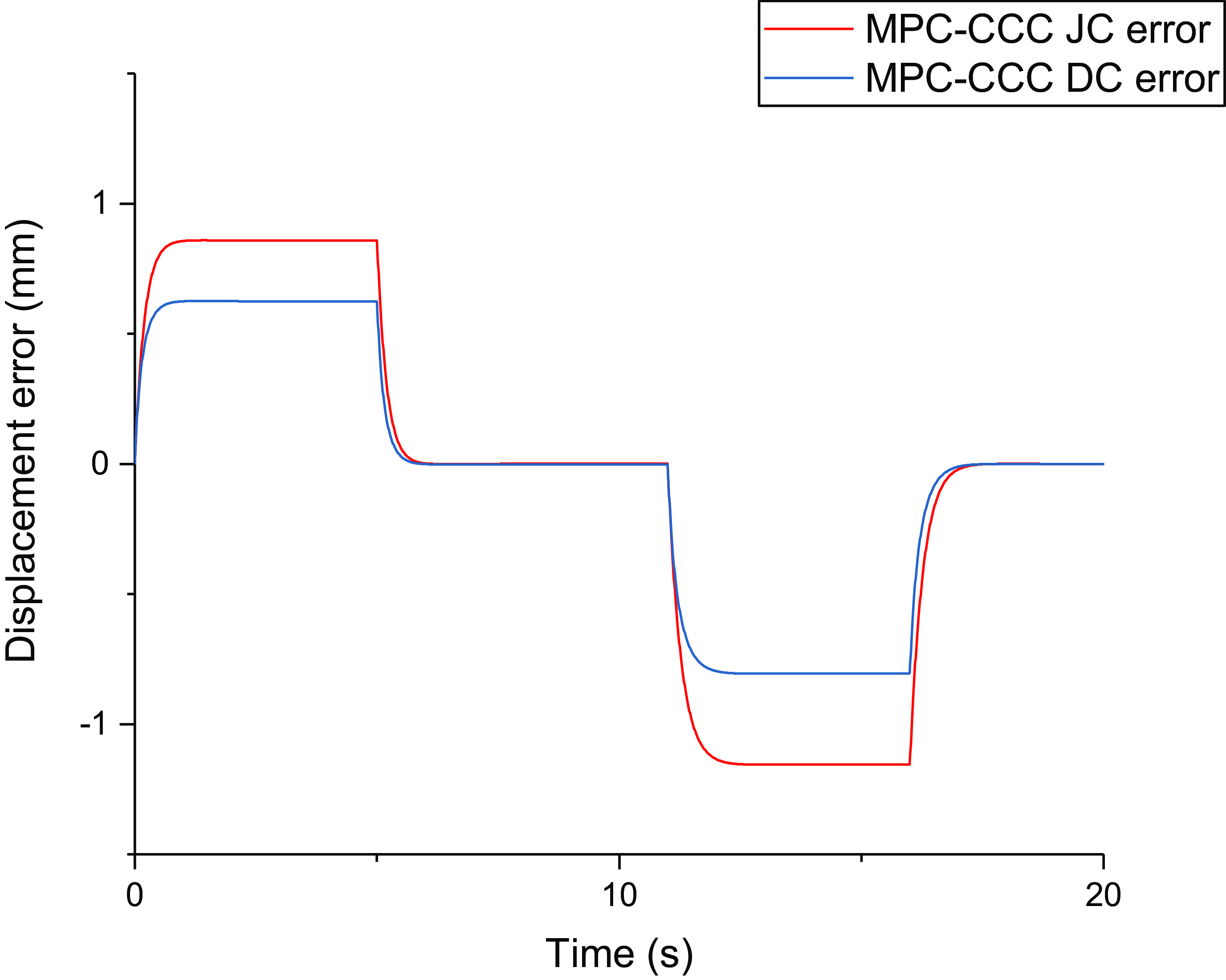
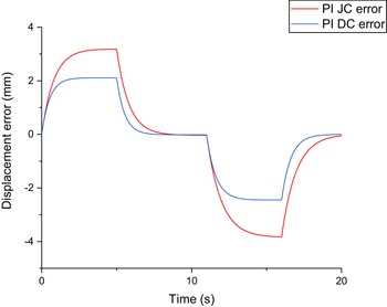
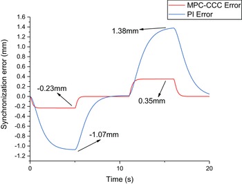
After the simulation, the displacements of the JC of MJU and the DC of MDU in different controllers are shown in Fig. 11. The displacements errors controlled by different controllers are shown in Figs. 12 and 13. The displacements synchronization errors can be seen in Fig. 14.
Ramp reference signal.

Displacements synchronization control in different controllers.

Displacements error in MPC-CCC controllers.

Displacements error in PI controllers.

Displacements synchronization errors in different controllers.

From Fig. 12, the response of the MPC-CCC controller approaches the target value faster than the PI controller. In the upward part of the reference signal, the time for the MPC-CCC controller to reach the target is close to 5.84 s, which is faster than the PI controller whose the fasted time is 7.53 s and slowest time is 8.96 s. The biggest time delay is up to about 3 s. In terms of steady-state error, the response of PI overshoots after reaching the target, and the overshoot increases gradually with time until it reaches the maximum value (0.03 mm). In the falling part of the reference signal, the MPC-CCC controller also has a faster response and less overshoot than the PI controller. The response of the MPC-CCC controller reaches the target value of about 16.89 s, which is faster than the PI controller (19.45 s). The biggest time delay between two controllers is up to about 2.56 s. After the response of the PI controller reaches the target, there is still an overshoot, while the overshoot of the MPC controller is close to 0. In Figs. 12 and 13, the maximum displacement error of the MPC-CCC controller is about 3.5 times the PI controller. From Fig. 14, in the upward part of the reference signal, the maximum synchronization error of MPC is –0.23 mm, and the PI’s is –1.07 mm which is about 4.7 times MPC’s. In the falling part of the reference signal, the maximum synchronization error of MPC is 0.35 mm, and the PI’s is 1.38 mm which is about 3.9 times MPC’s.
Key simulation parameters.

Sin reference signal.

Displacements synchronization control in different controllers.

From the simulation results, we can see that the MPC-CCC can not only guarantee the quick convergence of displacement error of a single system such as MDU and MJU but also have a good convergence of synchronization error in multielement systems (BRMR). MPC-CCC controller outperforms the PI controller in terms of response speed and steady-state error even in the condition of the reference signal changes drastically. The MPC-CCC controller can achieve the optimal control effect in both the dynamic tracking error, steady-state error, and synchronization error because of the characteristic of the MPC model-based predictive control algorithm and the continuous optimization of the cross-coupling term in the thought of CCC algorithm under constraints. From Fig. 12, the simulation results have shown that the maximum dynamic tracking error and the maximum steady-state error of this studied MPC controller are
 $-1.16\sim 0.86$
and
 $1.8\times 10^{-3}$
mm, respectively, which meet the actual technical accuracy requirements of ±5 and ±2 mm, respectively. From Fig. 14 we can see the maximum displacement synchronization error is 0.35 mm, which meets the actual technical accuracy requirements of ±5 mm.
4.2. JCs of MJU synchronization control simulation
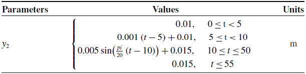
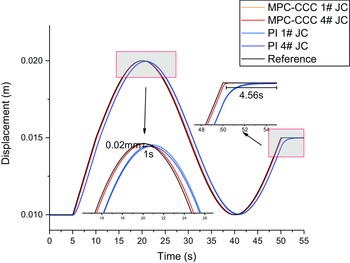
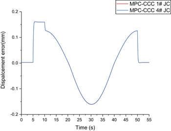
The simulation data is shown in Table III. Noted that the 1# JC with no load and 4# JC with 500 Kg load as shown in Table III. The reference is sin signal as shown in Table IV. The displacements of JCs of MJU in different controllers are shown in Fig. 15. the displacements errors controlled by different controllers are shown in Figs. 16 and 17. The displacements synchronization errors can be seen in Fig. 18.
Displacements error in MPC-CCC controllers.

Displacements error in PI controllers.

Displacements synchronization errors in different controllers.

BRMR experiment platform.

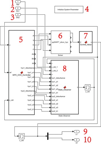
MPC-CCC controller graph in PLC. 1-Reference signal input; 2-Displacement feedback signal input of first cylinder; 3-Displacement feedback signal input of second cylinder; 4-Initialize system parameter; 5-MPC-CCC controller; 6-qpSWIFT; 7-Control value extractor; 8-State observer; 9-Control signal output of first cylinder; 10-Control signal output of second cylinder.

Displacements synchronization control in different controllers.

Displacements error in MPC-CCC controllers.

Displacements error in PI controllers.

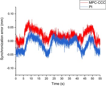
From the simulation results, taking the reference signal in Table IV, the response of the MPC-CCC controller is much faster than the PI controller. The PI response has a response delay of about 1 s and 0.02 mm displacement error at about time 21 s. In the same way, at the peak of the sin function, the response delay of the MPC-CCC controller is about 0 and the displacement error is about –0.0049 mm. In the displacement error, PI is about 4 times MPC-CCC. At end of the sin signal, PI response has about a 4.56 s delay compared with MPC-CCC. In Figs. 16 and 17, the MPC-CCC error range is about –0.16 to 0.16 mm. And PI error range is about –0.82 to 0.75 mm. The displacement error of PI is about 5 times MPC-CCC. In Fig. 18 the maximum synchronization error of PI is much bigger than MPC-CCC. In general, because of the control value optimization and cross-coupling error decrease made by CCC, the synchronization error of MPC-CCC is in a lower lever compared with PI. In this isomorphic condition, the synchronization error, dynamic, and steady-state error of MPC-CCC also satisfy actual displacement accuracy.
5. Experimental verification
5.1. JC of MJU and DC of MDU synchronization control experiment
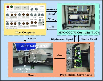
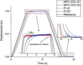
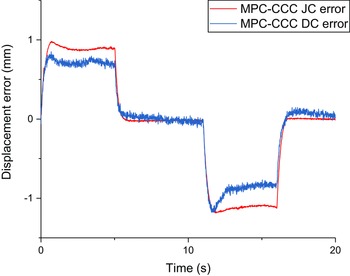
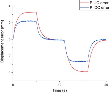
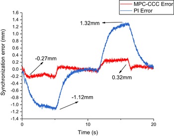
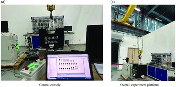
The structure of the BRMR experiment platform is shown in Fig. 19. The synchronous experiments were realized by PLC. The experiment parameters are identical to the corresponding simulation in Table I. The conference signals are identical to Table II. In this experiment, PLC is different from MATLAB/Simulink environment, so the MPC-CCC controller graph is arranged as shown in Fig. 20. After the experiment, the displacements synchronization control in different controllers is shown in Fig. 21. The displacements error in different controllers is shown in Figs. 22 and 23. Displacement synchronization errors in different controllers are shown in Fig. 24.
Displacements synchronization errors in different controllers.

Experiment process diagram.

Displacements synchronization control in different controllers.

Displacements error in MPC-CCC controllers.

Displacements error in PI controllers.

Displacements synchronization errors in different controllers.

In Fig. 21, PI still has a time delay of up to 1.99 s to reach the reference signal compared with MPC-CCC in the upward part of the signal. And PI still has a maximum overshoot of about 0.14 mm at time 11 s. On the contrary, MPC-CCC’s overshoot is nearly 0. In the downward direction, PI has about a 2.3 s time delay to reach 0 compared with MPC-CCC. The experiment displacement response of MPC-CCC is identical to the response in the simulation shown in Section 4.1. In Fig. 22, the maximum displacement error of MPC-CCC is –1.18 mm ∼ 0.98 mm which is much smaller than –3.92 mm ∼ 3.29 mm of PI as shown in Fig. 23. From Fig. 24, the error range of PI is –1.12mm ∼ 1.32 mm, the error range of MPC-CCC is –0.27 mm ∼ 0.32 mm, both of which is identical with the simulation. The experiment results verify the simulation and prove that the MPC-CCC control algorithm has better control effectiveness than PI.
5.2. JCs of MJU synchronization control experiment
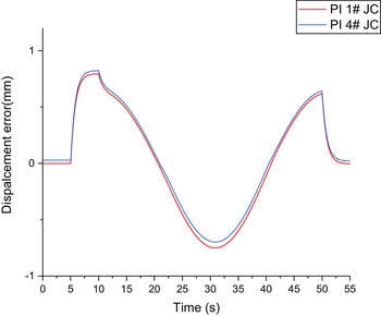
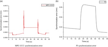
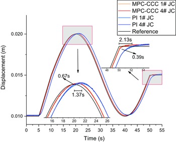
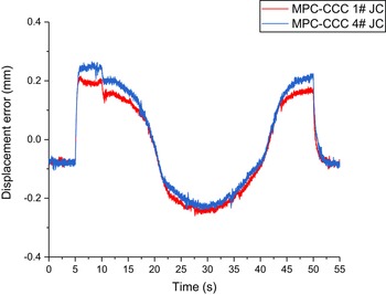
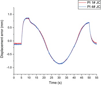
The experiment parameters are identical to the corresponding simulation in Table III. The conference signals are identical to Table IV. The structure of the controller is the same as in Fig. 20. In the JCs of MJU synchronization control, the #1 JC of MJU has no load, but the #4 JC of MJU has a 500 kg load. The load was prehanged for safety reasons (the sling of the crane is loose), and the experiment process pictures can be seen in Fig. 25. The displacement synchronization control in different controllers is shown in Fig. 26. The displacements error in different controllers is shown in Figs. 27 and28. Displacement synchronization errors in different controllers are shown in Fig. 29.
In Fig. 26, at top of the reference signal, MPC-CCC delayed 0.67 s to the reference signal, whereas PI delayed 1.37 s, ad MPC-CCC’s response was 0.7 s faster than PI’s. At the end of the signal, MPC-CCC’s time delay is about 0.39 s, and PI’s time delay is about 2.13 s. The trend is identical to the simulation. From comparing with Figs. 27 and 28, the MPC-CCC’s error range is –0.26 mm ∼ 0.27 mm is smaller than –0.88 mm ∼ 0.87 mm, and the error of PI is about 3 times MPC-CCC. The trend is also identical to the simulation result. In Fig. 29, we can see that there are fluctuations from about time 5 and 42.5 s, respectively, in accordance with Figs. 26, 27 and 28, that is because the #4 cylinder is not completely identical with 1# cylinder of MJU, the #4 cylinder is not usually used leading to a different friction model and the mess of payload also has an error. That is a systemic error. But the displacement error trend is identical between MPC-CCC and PI, and it can also prove the effectiveness of the MPC-CCC controller. In the same synchronization error range of 0.01 mm, the dynamic tracking error of PI is about 3 times MPC-CCC. The control effectiveness of MPC-CCC is verified in actual operation. In the end, the steady-state error, dynamic tracking error, and synchronization error under the control of the MPC-CCC algorithm meet the actual technical accuracy requirements of ±2, ±5, and ±5 mm, respectively.
6. Conclusion
This study aims to realize the high accuracy, stability, and high-efficiency transport of blankets through BRMR by using an innovative MPC-CCC method. First, the general state space mathematical model of BRMR is derived according to the physical-based method which includes two Movers’ hydraulic systems. Second, with the advantage of control value receding horizon optimization based on the model prediction output in the MPC algorithm and the advantage of fast convergence of the cross-coupling displacement error in the CCC algorithm the innovative MPC-CCC controller was proposed in this paper. The main idea of the controller is the cost function establishment which includes the model predictive optimization in MPC and the cross-coupling elimination term in CCC. Through the optimization of both terms, the controller can realize the convergence of single-system displacement error and multisystem synchronization error. This attempt is rarely used in the hydraulic system that needs high synchronization accuracy in the actual project. Third, to verify the BRMR synchronization control effectiveness of the MPC-CCC controller, because of experiment platform limits, the JC of MJU – DC of MDU and JC–JC of MJU were used for the simulation and experiments. And the comparison between MPC-CCC and the original PI used in Mover is obtained in simulation and experiments. From the simulation and experiment results in different reference signals, we can see that the results of the simulation and experiment are highly consistent. The displacement error and synchronization error of PI are 2.22 ∼ 3.33 times and 1.06 ∼ 2.44 times to MPC-CCC in experiments. MPC-CCC controller can reduce the displacement error and synchronization error by up to 70% and 59% compared to PI, respectively. And the accuracy of MPC-CCC satisfies the real requirement that the dynamic tracking accuracy of the displacement is ±5 mm, the steady-state accuracy of the displacement is ±2 mm, and the dynamic tracking accuracy of the synchronous displacement is ±5 mm.
Despite the strengths of this study, there are some limitations to consider. For example, due to the small difference in friction between #1 and 4# hydraulic cylinders of MJU, these two cylinders are not entirely identical leading to fluctuations in the reference signal turning points. Nevertheless, the results of this study provide valuable insights into the synchronization control in BRMR. This work has also provided a theoretical basis and practical experience for the future applications of the MPC-CCC control algorithm in the synchronous control of the BRMR and the synchronous transportation of the blanket.
Looking forward, future research could enhance these findings and explore better performance in MPC-CCC controller by considering nonlinear parts to optimize the mathematical model.
Author contribution
Dongyi Li: conceptualization, data curation, formal analysis, investigation, methodology, software, validation, visualization, and writing – original article. Kun Lu and Yong Cheng: conceptualization, funding acquisition, project administration, resources, supervision, visualization and writing – review and editing. Huapeng Wu and Heikki Handroos: conceptualization, methodology, supervision, visualization, and writing – review and editing. Xuanchen Zhang: methodology and visualization. Xinpeng Guo, Songzhu Yang, Liansheng Du, and Yu Zhang: data curation, visualization.
Financial support
This work was supported by the National Key R&D Program of China with Grant No. 2017YFE0300503, Comprehensive Research Facility for Fusion Technology Program of China under Contract No. 2018-000052-73-01-001228, and Anhui Extreme Environment Robot Engineering Laboratory and the China Scholarship Council with No. 202206340050.
Competing interests
The authors declare no Competing interests exist.
Ethical approval
Not applicable.