Introduction
With the increase in the requirement of various communication system applications, the number of antennas in handheld devices is increasing day by day. So far, a handheld device has about a dozen of antennas, which can cover the existing frequency bands such as long-term evolution (LTE), Global System for Mobile Communication (GSM), Universal Mobile Telecommunication System (UMTS), Digital Cellular System (DCS), Personal Communications Service (PCS), Wireless Fidelity (Wi-Fi), Worldwide Interoperability for Microwave Access (WiMAX), Wireless Local Area Network (WLAN), and Wireless Medical Telemetry (WMT). Upcoming fifth-generation (5G) devices may carry some half-dozen more antennas for 5G, which makes the handheld devices huge. Since space is limited in handheld devices, a multiband antenna with compact size is required. Also designing a multiband antenna with restricted size is very challenging [Reference Huang, Du and Wang1].
Nowadays, many techniques have been studied to design multiband antennas in limited space. Monopole, slot, and loop antennas can generate multiple resonant modes, so this antenna can be used as a multiband antenna [Reference Lee and Sung2–Reference Palmeri, Bevacqua, Morabito and Isernia12]. In [Reference Lee and Sung2], a frequency reconfigurable antenna that can cover LTE and WWAN operating bands by adjusting two pin diodes for the handsets is discussed. This antenna is of size 36.5 × 10 mm2 with good efficiency. For tablet computer applications, the half loop frame antenna [Reference Wong and Tsai3] and inverted-F antenna [Reference Wong and Tsai4] operating on the LTE band are discussed; for both cases, metal casing is used to increase tablet’s robustness. The metal-rimmed multiband antenna for smartphone applications is discussed in [Reference Huang, Du and Wang5–Reference Zhang, Ban, Guo and Yu9]. Huang et al. [Reference Huang, Du and Wang5, Reference Huang and Du6] reported a monopole antenna with 2 and 7 mm ground clearance, which can cover two bands (0.67–1.05 GHz and 1.6–2.8 GHz). A compact dual-band multimode monopole antenna [Reference Yang, Zhao, Yang, Nie and Liu Qing7] designed for smartphones, the proposed antenna covers a −6 dB impedance band for GSM, DCS, PCS, UMTS, and LTE.
Thamil et al. [Reference Thamil Selvi, Thiruvalar Selvan and Babu13] presented a multiband antenna inspired by a planar waveguide-fed split-ring resonator (SRR) metamaterial; the reported antenna size is 40 × 40 × 0.8 mm3 with six resonating bands (UTMS, WLAN, WiMAX, C-band, WLAN-IEEE 802.11ax). Antenna boosters for wireless devices using two reconfigurable multiband [Reference Anguera, Andújar and Leiva14] antennas are investigated, which have very small booster size less than 90 mm2 and operate in two bands (680–960 MHz and 1700-2600 MHz) with appreciable efficiency. Designing a wideband antenna is another area of interest [Reference Yang, Sun and Li15]; there are many techniques to widen the bandwidth of an antenna in a small space, such as lumped-element matching method, reconfigurable technique, multiple branch technique, coupled fed method, and many others. In [Reference Tang and Du16], a T-shaped monopole antenna followed by two parasitic ground strips covering the UMTS, LTE 2500, DCS, and PCS bands for smartphones is reported.
This paper proposes a compact multiband antenna for Wi-Fi, WiMAX, S-band, C-band, 4G, and 5G applications without any lumped element for matching. The proposed antenna is a combination of folded monopole and M-shape strip type antenna with the small size of 26.8 × 10.8 mm2 and printed on the left corner of an inverted C-shaped substrate. The antenna can receive 14 smaller operating bands. The results are simulated and optimized in computer simulation software.
Antenna design
Antenna arrangement
The geometry of the proposed antenna is illustrated in Fig. 1(a). The antenna is designed on a C-shaped Fr-4 substrate of dimensions 120 × 60 × 0.8 mm3 with relative permittivity and loss tangent of 4.4 and 0.02, respectively. The ground plane is designed on the back side of the substrate, including an L-shaped ground plane of 120 × 25 mm2 printed on the front side of the substrate. The proposed antenna, which is shown in Fig. 1(b), is printed on the left corner of the substrate with dimensions of 26.8 × 10.8 mm2. The proposed antenna is fed by a 50 ohm coaxial cable from point P as shown in Fig. 1(b).
(a) The geometry of the proposed multiband antenna. (b) The detail dimensions of the antenna.

The proposed antenna consists of folded monopole antennas (Ant 1 and Ant 2) and an M-shaped strip (Ant 3), responsible for low and high-frequency bands. The antenna is fed with a microstrip feed line of 50 ohms impedance. The proposed antenna is composed of three antennas, i.e. Ant 1, Ant 2, and Ant 3, as illustrated in Fig. 1(b). Ant 1 contributes to 1300 and 4200 MHz band, Ant 2 is responsible for 3540, 4880, and 5448 MHz bands, and a total of seven resonance bands are obtained after the inclusion of the M-shaped strip (Ant 3). In the following section, we investigate and discuss the proposed antenna in details. The broad dimensions of the proposed antenna are specified in Table 1.
Dimensions of the proposed antenna

Flow chart
The flowchart of the proposed multiband antenna is shown in Fig. 2.
The flowchart of the proposed multiband antenna.

Antenna analysis
Some parameters and current distributions are studied to find out the mechanisms of the proposed antenna. The proposed antenna consists of two folded monopole antennas and M-shaped strip. Figure 3 illustrates a comparison of the simulated reflection coefficient (S-parameter) of several antenna geometries. Ant 1 generates two resonant modes for the LTE 1500 and 5G band. Then after adding the strip of Ant 2, two more resonant modes are excited, which is responsible for the WiMax band. Next, M-shaped structure is added to Ant 1 and Ant 2, which makes Ant 3. Three resonance modes are excited after adding the M-shaped structure at the frequencies of 2272, 3152, and 5606 MHz, and the impedance matching for these modes is good. So, the studied antennas may cover 3G, 4G, 5G, UMTS, Wi-Fi, and WiMax bands.
Simulated reflection coefficients for different antennas.

Parametric study
This antenna has been designed with different values of L5, which is depicted in Figure 4 to show how they affect each resonant mode. Figure 4 shows the S-parameter versus frequency curve for L5 increasing from 13 to 16 mm; the resonance mode of the middle band and high band changes accordingly, and the lower band and second resonance mode of the middle band are unchanged.
Simulated reflection coefficients of the studied antenna as a function of L5.

Current distribution
In order to gain a better understanding of the resonant mechanisms employed by the studied antenna, the surface current distributions at frequencies of 1400, 2200, 3400, 4000, and 5500 MHz are illustrated in Fig. 5(a–e). Figure 5 illustrates the different colors of the current intensity of each point as a function of its minimum and maximum values. As can be seen from the figure, the red region shows the peak in the distribution of currents, while the blue region shows the lack of distribution of currents, and the triangular arrows show the flow of currents. Figure 5(a) displays that the current is strong in strip ABC, ADE, and GF, which indicates that the resonance at 1400 MHz is related to the 0.25-λ mode. At 2200 MHz, the current is distributed along strip ABC, as shown in Fig. 5(b), with the surface current being strong at point A and weak at point C. It shows that the resonance at 2200 MHz is related to the 0.5-λ mode. Figure 5(c) illustrates the simulated current distribution at 3400 MHz for the studied antenna, where peak current distributions are observed along ABC and GF paths. The surface current is strong at point A and weak at point B and C, so the 0.75-λ mode is excited at 3400 MHz. At 4000 MHz as presented in Fig. 5(d), the surface current is mostly distributed on the strip ABC and ADE, the current is strong at point A and weak at point B, D, and F, and the number of nulls has been observed in strip ADE. It can be said that at 4000 MHz, the antenna produces a 0.25-λ mode on strip ABC and a higher mode on strip ADE. At 5500 MHz, the current is distributed across strip ABC and ADE. As shown is Fig. 5(e), the surface current is strong at point A, B, and D. Number of nulls is observed in strip ABC and ADE; thus, higher-order modes are active at 5500 MHz for sections ABE and ADE.
The simulated surface current distribution of the studied antenna: (a) 1400 MHz, (b) 2200 MHz, (c) 3400 MHz, (d) 4000 MHz, and (e) 5500 MHz.

Experimental result
The proposed antenna is fabricated and tested to validate its performance in the analysis discussed above. Figure 6 illustrates the picture of the fabricated antenna. 50-ohm coaxial cable is used to feed the antenna. An Anritsu MS46122B vector network analyzer is used to evaluate the S11 parameter of the fabricated antenna.
A photograph of the fabricated antenna: (a) front view and (b) back view.

Figure 7 illustrates the measured and simulated S11 (reflection coefficient) parameter of the proposed antenna. The simulated result is indicated by the red solid line, and the measured result is indicated by the violet dashed line. Observations indicate that the simulation and measurement results appear to be in good agreement, while there is a slight frequency difference due to manufacturing inaccuracies and matching network losses. Measured −10 dB bandwidths are 210 MHz (1200–1410 MHz), 100 MHz (2200–2300 MHz), 193 MHz (3000–3193 MHz), 180 MHz (3330–3510 MHz), 390 MHz (4110–4500 MHz), 4971 MHz, 577 MHz (5300–5877 MHz), and 700 MHz (7100–7800 MHz). Hence, the proposed antenna supports 14 bands, i.e. LTE1500/2300/3500/5900, UTMS/PDC/Wi-Fi/WiMAX, S-band, C-band, and 5G (n40, n50, n51, n77, n78, and n79).
The measured and simulated reflection coefficient of the studied antenna.

The simulated radiation pattern in the E and H planes of the suggested antenna at 1400, 2200, 3400, 4000, and 5500 MHZ are displayed in Fig. 8. At frequencies 1400 and 2200, the studied antenna shows a nearly constant radiation patterns that is omnidirectional in the H-plane and bidirectional in the E-plane. In higher bands, the radiation patterns become more complex as more variations and nulls are observed. As the proposed antenna operates at higher frequencies, it exhibits unwanted side lobes in conjunction with the main lobe due to higher-order mode excitation.
The radiation pattern of the studied antenna: (a) 1400 MHz, (b) 2200 MHz, (c) 3400 MHz, (d) 4000 MHz, and (e) 5500 MHz.

The efficiency of an antenna is the ratio of radiated power of the antenna to the applied power of the antenna. The radiation efficiency antenna differs from the total efficiency of the antenna due to losses attributed to impedance mismatch.
The overall efficiency [Reference Balanis17] is
 \begin{equation}{\eta _{\textrm{o}}} = {\eta _{\textrm{r}}} \times {\eta _{\textrm{c}}} \times {\eta _{\textrm{d}}},\end{equation}
where η o = total efficiency, η r = reflection (mismatch) efficiency, η c = conduction efficiency, and η d = dielectric efficiency.
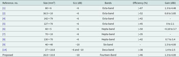
The gain and efficiency of the proposed antenna are represented in Fig. 9. According to Fig. 9, based on the five operational bands, the gains are 1.3, 2.11, 3.4, 4.0, and 2.60 dBi, respectively. Maximum efficiencies of 59%, 54%, 57.6%, 60.2%, and 46% are measured for the 1st, 2nd, 3rd, 4th, and 5th impedance bands, respectively, which is suitable for wireless communications. The efficiency of the proposed antenna is slightly less than 50% in the 5th band due to the excitation of surface waves. Surface waves propagate near the excitation point and returned when they meet the ground or dielectric-to-air boundary. As a result of this trapped field, a portion of the signal energy is absorbed by the substrate, leading to a decrease in efficiency. The compartaive study of the proposed multiband antenna with the multiband antennas available inliterature is represened in Table 2.
The efficiency and gain of the proposed multiband antenna.

Comparative study of the proposed multiband antenna with the multiband antennas available in literature

Conclusion
We present a folded monopole antenna with M-shaped strip for portable communication that complies with the requirements of next-generation wireless communication and can operate over multiple frequency bands. The size of proposed antenna is 26.8 × 10.8 mm2 with a simple architecture. The fabricated antenna achieved seven −10 dB operational bands and could cover 14 smaller service bands in the 3G, 4G, 5G, Wi-Fi, WiMAX, C-band, and S-band. In addition, a maximum gain of 1.3 to 4.00 dBi and efficiency of over 46% are achieved. In addition to exhibiting satisfactory radiation efficiency, the studied antenna design also exhibits a nearly omnidirectional radiation pattern, making it an ideal candidate for use in portable communications.
Competing interest
The authors report no conflict of interest.
Author contributions
Pranjalee Mishra designed the antenna and performed simulations under the guidance of K. D. Kulat. Both the authors contributed equally to analyzing data and reaching conclusions and in writing the paper.

Pranjalee Mishra received B.E. degree in electronics and telecommunication from Shri Shankaracharya Institute of Engineering & Technology, Bhilai, CG, India, in 2013. She further obtained M.Tech degree in digital communication from SCOPE College of Engineering & Technology, Bhopal, MP, India, in 2017; she is currently pursuing her Ph.D. degree from Visvesvaraya National Institute of Technology, Nagpur, India. Her areas of interest include antenna design, metamaterials, wideband antenna, multiband antenna, and millimeter-wave communication. She is also guiding undergraduate students.

Prof. Kishor D. Kulat is currently working as professor in the Department of Electronics and Telecommunication Engineering, Visvesvaraya National Institute of Technology, Nagpur, India. He has 30 years of teaching experience. He received Ph.D. from Visvesvaraya National Institute of Technology, Nagpur, India. He has supervised 29 doctoral dissertations. He has published more than 120 journal and conferences papers in national and international journals and conferences. His research interest are wireless communication, devices and circuits, antenna design, MIMO, multiband antenna, and metamaterial.