I. INTRODUCTION
Large surface area and controlled porosity titanium dioxide is an interesting catalyst support because enhanced activity and selectivity have been observed with the group VIII A metals (Fe, Ni, Pd, Pt, …), which was explained by the so-called “strong-metal support interaction” (SMSI).Reference Tauster, Fung and Garten1,Reference Dulub, Hebenstreit and Diebold2 Moreover, TiO2 is also the object of great interest for solar cell and photocatalysis applications.Reference Hoffmann, Martin, Choi and Bahnemann3,Reference Barbé, Arendse, Comte, Jirousek, Lenzmann, Shklover and Grätzel4
The final purpose of the work reported here is the deposition of catalytic layers on metallic structured reactors. These devices are built by stacking metallic plates incorporating narrow parallel channels coated with a thin layer of catalyst.Reference Haas-Santo, Fichtner and Schubert5–Reference Thormann, Pfeifer, Schubert and Kunz7 They have many advantages like enhanced heat and mass transfer, excellent safety, and quick response time.
For the application of catalytic TiO2 layers onto metallic substrates, the electrophoretic deposition technique (EPD) is very versatile. The working principle of EPD is based on the movement of charged particles in an electric field. The particles move toward the working electrode due to the applied cell voltage and their accumulation on this electrode leads to the formation of a homogeneous layer. This process has several advantages: it is cost effective and it is also possible to coat complex shaped substrates, besides simple planar substrates. Rather large thicknesses, up to several millimeters can be reached for the coatings,Reference Uchikoshi, Suzuki, Tang, Okuyama and Sakka8 in contrast to coatings done with the dip-coating technique, where the thickness for one single dipping cycle is generally limited to a few micrometers.Reference Negishi, Takeuchi and Ibusuki9–Reference Watanabe, Fukayama, Miyauchi, Fujishima and Hashimoto11 Another advantage of EPD is that the porosity of the coatings can be finely tuned, depending on the experimental conditions.
The dependence of the deposited mass on the EPD parameters is given by the Hamaker lawReference Besra and Liu12 (Eq. 1).
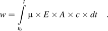 $$w = \int\limits_{{t_0}}^t {{\rm{\mu }} \times E \times A \times c \times dt\quad .}$$
where w is the deposit yield (in g), E is the electric field strength (in V/m), μ is the electrophoretic mobility (in mReference Dulub, Hebenstreit and Diebold2/V/s), A is the surface area of the electrode (in m2), c is the particle mass concentration in the suspension (in g/L), and t is the deposition time (in s).
For industrial applications, water is preferred as a solvent because it is cheap, nontoxic, and has a high relative permittivity (80.1 at 20 °C). However, when the cell voltage exceeds the water splitting potential (−1.23 V at 25 °C), gas evolution is expected to occur at the electrodes. The formation of H2-gas on the deposition cathode is reported to have detrimental effects on the coatings because the gas bubbles prevent good adhesion to the substrate and lead to cracks in the deposit.Reference Uchikoshi, Ozawa, Hatton and Sakka13 Numerous techniques have been developed to overcome this problem, e.g., the deposition on a microporous membrane,Reference Nold and Clasen14 on palladium electrodes,Reference Uchikoshi, Ozawa, Hatton and Sakka13 the application of voltage pulses,Reference Neirinck, Fransaer, Biest and Vleugels15 or the use of porous molds to minimize the gas evolution.Reference Ryan Perera16 Nevertheless, to avoid this problem, more often organic solvents are used.Reference Besra and Liu12,Reference Lin, Yang, Feng, Tsung and Su17–Reference Moskalewicz, Czyrska-Filemonowicz and Boccaccini19
A dispersion used for EPD should have a good stability and the particles should have a high electrophoretic mobility,Reference Castro, Ferrari, Moreno and Durán20 often calculated using the Henry equationReference Besra and Liu12:
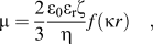 $${\rm{\mu }} = {2 \over 3}{{{{\rm{\varepsilon }}_{\rm{0}}}{{\rm{\varepsilon }}_{\rm{r}}}{\rm{\zeta }}} \over {\rm{\eta }}}f({\rm{\kappa }}r)\quad ,$$
where μ is the electrophoretic mobility (in m2/V/s), ε0 is the vacuum permittivity (8.8542 × 10⁻¹² F/m), εr is the relative permittivity of the solvent, ζ is the zeta potential (in V), η is the solvent dynamic viscosity (in Pa s) and f(κr) is the Henry function, which depends both on the thickness of the double layer (1/κ) and on the core radius (r) of the particle. This equation leads to two limiting cases: for small κr (small particles in a low dielectric constant media), the Henry function is close to 1, which corresponds to the so-called Huckel limit, whereas for large κr (aqueous media with a moderate electrolyte concentration), the Henry function approaches 1.5, which corresponds to the Smoluchowsky limit. From Eq. (2), it can be concluded that an EPD suspension should have a low viscosity, a high relative permittivity, and a high zeta potential to get the highest electrophoretic mobility.
In this work, EPD was performed using two kinds of TiO2 suspensions. First, colloidal dispersions of TiO2 nanoparticles in water synthesized by hydrolysis of a Ti-alkoxide, and second, dispersions of the same TiO2 nanoparticles in ethanol. The EPD with dispersions of nanopowders has already been reportedReference Lin, Yang, Feng, Tsung and Su17,Reference Lebrette, Pagnoux and Abélard21,Reference Abdullah and Sorrell22 but only rarely with colloidal suspensions synthesized from a sol–gel processReference Castro, Ferrari, Moreno and Durán23,Reference Wang and Chou24 Dispersions prepared by the sol–gel method have the advantage of being stable, without the necessity to add dispersants. Furthermore, the very small particle size of these colloids allows tuning the porosity on a wider range.
In order to improve the dispersion stability, the adhesion of the coatings and to reduce the formation of cracks, five different chemical additives were selected in this study: Tiron, Pluronic® F127, polyethyleneimine (PEI), the poly(acrylic acid) (PAA) sodium salt, and carboxymethyl cellulose (CMC) sodium salt. These additives lead in preliminary experiments to the best EPD coatings considering the three criteria: thickness, adherence, and surface area.
The sodium salt of poly(acrylic acid) (PAA) is used as an organic binder in aqueous TiO2 dispersions.Reference Sato, Kondo, Tsukada, Ishigaki and Kamiya25–Reference Liufu, Xiao and Li28 It improves the stability of dispersions, thanks to its ionizable carboxylate groups. In the literature, it is generally used for dispersions in water.
Polyethyleneimine (PEI) is a polyelectrolyte with primary, secondary, and tertiary amine groups in the ratio 1:2:1. It is considered as a good EPD additive to disperse nano-TiO2 and therefore also called a universal EPD agent.Reference Fukada, Nagarajan, Mekky, Bao, Kim and Nicholson29 It was reported that it could create a positive zeta potential for TiO2 dispersions on the whole pH range.Reference Sentein, Guizard, Giraud, Yé and Ténégal30,Reference Tang, Uchikoshi, Ozawa and Sakka31
The Tiron (1.2-dihydroxybenzene-3.5-disulfonic acid) is a salt used to disperse TiO2 nanoparticles. It improves the stability and electrophoretic mobility of the dispersions used for EPD.Reference Lebrette, Pagnoux and Abélard21 In the literature, it is reported that Tiron adsorbs to metal atoms like aluminum or titanium through a negatively charged complex using the hydroxyl groups.Reference Laucournet, Pagnoux, Chartier and Baumard32
The polyelectrolyte carboxymethyl cellulose (CMC) is used as a binder to improve the adherence of TiO2 particles on the substrate.Reference Mancini, Nobili, Tossici and Marassi33,Reference Zhao, Bai, Ren, Guo and Wu34
Pluronic® F127 is a hydrophilic nonionic surfactant. This is a ABA type triblock copolymer, where A is made of hydrophilic poly(ethylene oxide) (PEO) and B of more hydrophobic poly(propylene oxide) (PPO). The average number of EO units in the PEO blocks is 101, whereas the average number of PO units in the PPO blocks is 56.35 We used it to increase the porosity and the adhesion of the coatings.Reference Bleta, Alphonse and Lorenzato36
II. MATERIALS AND METHODS
A. Synthesis of EPD dispersions
The TiO2 colloidal dispersion used for the EPD was synthesized by hydrolysis of Ti-isopropoxide (>98%, Acros Organics, Geel, Belgium) in a large excess of diluted aqueous nitric acid (68%, Acros Organics) solution (H2O/Ti ≈ 90 and H+/Ti = 0.2) as described in one of our previous publications.Reference Alphonse, Varghese and Tendero37 The pH of the dispersion was about 1.4, and the molar concentration of Ti was in the range of 0.6–0.65 M.
All the additives were introduced into the TiO2 colloidal dispersion after its synthesis. In Table I, the concentrations of the additives are always given with respect to the mass of TiO2 in the dispersion. Poly(acrylic acid) sodium salt (PAA, MW 5100 g/mol, Fluka, Lyon, France) was dissolved in water and added to the TiO2 dispersion. Polyethyleneimine (PEI, 50 wt% aqueous solution, branched, MW 60000 g/mol, Acros Organics) was further diluted with water before it was added to the dispersion. Carboxymethyl cellulose sodium salt (CMC, MW 90000 g/mol, degree of substitution 0.60–0.95, Fluka) was dissolved in water and added to the dispersion. Pluronic® F127 (MW ∼ 12,600 g/mol, Sigma, Lyon, France) was added as a powder to the TiO2-dispersion with a concentration of 44 wt%. Tiron (Acros Organics) was added as a powder to the sol in a concentration of 0.1 wt%. After the introduction of the additives, the dispersions were stirred for at least 24 h before further use.
Dispersions used for the EPD experiments. c add is the additive concentration (in wt% relative to the amount of TiO2 in the dispersion). U is the optimum EPD voltage. t is the deposition time.

B. Dispersions in ethanol
The dispersions in ethanol were prepared by drying the colloidal hydrosols at 40 °C until 10 wt% of residual water was left. This paste was dispersed in ethanol by ultrasonication for 10 min (Branson 1510 Ultrasonic Cleaner, Danbury, CT, 42 kHz), followed by dispersion with an Ultra-Turrax IKA T25 Homogenizer (Staufen, Germany) for 5 min at 15,000 rpm. The TiO2 concentration in these ethanol dispersions was 1 wt%.
C. Electrophoretic deposition
For the EPD experiments, constant voltage conditions were used. The setup consisted of a 50 mL beaker as the EPD cell (filled with 10 mL of the TiO2 dispersion), a holder for the electrodes, which was made of two alligator clips attached to an epoxide block, a platinum mesh as the counter electrode, a 316 L stainless steel substrate (15 × 20 × 1 mm) as the working electrode, a DC Power Supply Xantrex XFR 600-2 (Burnaby, Canada; used for the higher voltage range), a Source Meter Keithley 2611A (Cleveland, OH; used as the DC source for the voltage range 2–5 V) and a Multimeter ITC 580 (Grote, Lillois, Belgium) to measure the current. The active surface area was kept constant (1.5 cm2) by using a mask (adhesive tape). The distance between the electrodes was fixed at 2.0 cm.
For each dispersion, the optimum voltage (1.5 V up to 50 V) was determined in a preliminary work (not presented here for the sake of clarity). Different deposition times, TiO2 concentrations, and additive concentrations were tested. The criteria of choice were the thickness, the homogeneity, and the adherence of the coatings. The optimized EPD parameters from this previous study are summarized in Table I.
D. Pre- and posttreatment of substrates
Prior to each EPD, the steel substrates were immersed in a degreasing solution (Turco® 4181, Henkel, Düsseldorf, Germany) at 80 °C for 1 h. After thorough washing with deionized water, the substrates were immersed for 10 min in an ultrasonic bath in an ethanol–acetone mixture (1:1) and finally dried at 80 °C.
After EPD, the coated substrates were dried for 1 h at 40 °C and then heated in air at 350 °C for 2 h in a furnace to remove the additives and to improve the adherence of the deposits.
E. Characterization techniques
For imaging, the EPD coatings and for some thickness measurements, an Optical Microscope Keyence VHX 1000 (Itasca, IL) with the VH-Z100R objective (VH-Z500R for 5000x magnification) was used. Thickness measurements were done with an Interferometer-Profilometer (Zygo New View 100, Middlefield, CT).
A cross-section was prepared by embedding the piece in an epoxy resin (Struers EpoFix) followed by abrasion of several mm (with 120 μm grain) and polishing (down to 10 μm grain using Escil diamond spray), both done by a lapping machine (Struers, TegraPol-15, Champigny sur Marne, France).
BET surface measurements were carried out with a gas adsorption analyzer Micromeritics ASAP 2010. Krypton was used as the adsorption gas. Before the analysis, the samples were degassed by heating under vacuum (1 Pa) at 300 °C for 2 h.
The electrophoretic mobility and the particle size were measured with a Malvern instrument (Zetasizer Model ZEN3691, Worcestershire, UK). A polycarbonate folded capillary cell (DTS 1061) was used.
To estimate the adhesion of the EPD coatings on the substrate, the following adhesion test was done: the coated substrates after the posttreatment were dropped through a 30-cm-long vertical cylinder; the mass of the substrate before and after the drop was compared. From the mass difference, the adhesion of the coating on the steel substrate was estimated.
III. RESULTS AND DISCUSSION
A. Characterization of the TiO2 dispersions
The colloidal dispersions in water are composed of aggregates, with a chain-like structure, of anatase (∼90%) and brookite crystallites (5–6 nm). Stable sols composed solely of anatase crystallites (4 nm) can be prepared by complexing partially the TIP by acetylacetone before hydrolysis.Reference Alphonse, Varghese and Tendero37
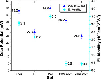
Electrophoretic mobilities of the different suspensions are reported in Fig. 1. The electrophoretic mobility is a very important characteristic of the suspensions used for EPD because it has a main influence on the deposition kinetics.Reference Besra and Liu12 Except for PEI, the additives decreased the electrophoretic mobility. The zeta potential, calculated from the electrophoretic mobility Eq. (2), was also reported in Fig. 1. We see that all zeta potentials are high enough to prevent the dispersions from agglomeration for the time needed for the deposition.
Electrophoretic mobility measurement and zeta potential of EPD suspensions.

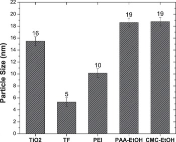
The average particle size, measured for the various dispersions, is shown in Fig. 2. For the aqueous colloidal dispersion without additives, the measured particle size was 15 nm. Addition of PEI decreased this value to 10 nm. The smallest particle size (5 nm) was measured for the TF dispersion. This value is very close to the size of the primary particles,Reference Alphonse, Varghese and Tendero37 which indicates a very good dispersion. The dispersions in ethanol were not as good as with a particle size close to 20 nm.
Particle size measurement of EPD suspensions.

B. Images of the TiO2 deposits
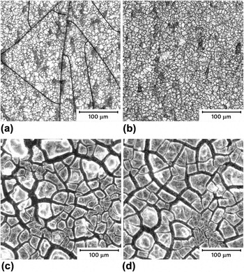
The EPD coatings after the thermal posttreatment at 350 °C in air were observed with an optical microscope (Fig. 3.1). All coatings showed cracks, which appeared after the calcination at 350 °C. The coatings prepared from the aqueous sols exhibited very fine cracks, whereas large cracks were formed on layers produced by ethanol dispersions. This difference is probably due to the faster evaporation and different surface tension of ethanol.
FIG. 3.1. Optical microscope images of EPD coatings after thermal posttreatment at 350 °C in air. (a) TF-Sol; (b) PEI-Sol; (c) PAA-Sol; (d) CMC-Sol (See Table I for the description of EPD parameters).
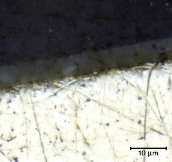
FIG. 3.2. Optical microscope images of a cross-section of a TF-coating after calcination at 350 °C (deposition time = 5 min, other EPD parameters as given in Table I). The bottom part of the image is the stainless steel substrate.


An optical microscope image of a cross-section of the TF coating is given in Fig. 3.2. It shows that the interface between the TiO2 film and the stainless steel substrate (bottom part) was very good; the TiO2 layer closely followed the roughness of the substrate. The coating thickness was in the range of 4–6 μm.
C. EPD experiments
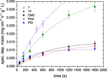
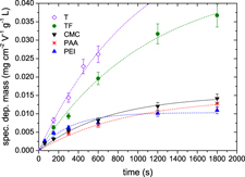
All EPD experiments were done under constant voltage conditions.Reference Sarkar and Nicholson38 It was observed that the deposition rate decreases with increasing time (Fig. 4). This may occur because the poor conductive TiO2 layer, forming on the working electrode, leads to an increase of resistance and a decrease of the electric field.Reference Baldisserri, Gardini and Galassi39 Besides, the depletion of the TiO2 concentration in the vicinity of the working electrode could have a similar effect. The T-sol plot is not shown for time exceeding 600 s because, in this case, the coated mass could not be properly measured due to the bad adhesion of the layer.
Specific deposited mass versus deposition time t, 5 different additive combinations were used. The deposited mass was divided by the electrode surface, the EPD voltage, and the TiO2 concentration. For explanation of the labels and concentrations, refer to Table I.

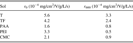
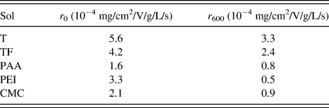
For better comparison, the deposited mass was divided by the electrode surface, the applied voltage, and the initial TiO2 concentration. The highest deposited masses were reached for the coatings made with aqueous dispersions, the best being the T-sol followed by the TF-sol. However, F127 decreases the electrophoretic mobility, which explains the lower deposition rate of the TF-sol in comparison to the T-sol. The dispersions in ethanol gave lower deposited masses. The deposition rates, calculated from the slopes of the fitted curves (see Fig. 4), are reported in Table II. The highest deposition rates were obtained with the T- and the TF-sol. These deposition rates are still rather high after a deposition time of 600 s. Considering the other sols, the highest initial deposition rate was obtained with the PEI-sol. However, the rate became lower than the rates of the CMC- and PAA-sol for a deposition time exceeding 600 s. During the process, the deposition rates decreased continuously until finally the deposition curves of PEI-, CMC- and PAA-sol reached a plateau.
Deposition rates, obtained from the slopes of the fitted curves in Fig. 4; r 0 is the initial deposition rate and r 600 the deposition rate at 600 s.
As the ethanol dispersions have lower electrophoretic mobilities μel (Fig. 1) than the water dispersions, higher voltages are needed to obtain comparable deposition rates. Furthermore, it can be assumed that the effect of water splitting is much higher for the aqueous dispersions than in ethanol, where no gas evolution was observed. The effect of water splitting on the deposition process is complex because it could lower the current used for the electrophoresis, but it also raises the pH, destabilizing locally the dispersion, which can lead to aggregation in the vicinity of the working electrode. Finally, as reported in the literature, the gas bubbles could negatively affect the adhesion on the substrate.
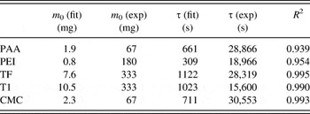
The measured deposited mass curves were fitted with an exponential function as a basic model in an attempt to model the deposition processReference Ferrari, Moreno and Cuesta40 [Eq. (3)]. This model takes into account only the depletion of the particle concentration during the EPD.
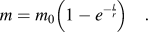 $$m = {m_0}\left( {1 - {e^{ - {t \over r}}}} \right)\quad .$$
In Eq. (3), m 0 is the initial mass of TiO2 in the sol (in g), and τ is the time constant:
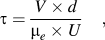 $$\tau = {{V \times d} \over {{{\rm{\mu }}_e} \times U}}\quad ,$$
where V (cm3) is the volume of the dispersion, and d (cm) is the electrode distance.
The best fitting parameters m 0 and τ are reported in Table III and compared with the experimental values. Obviously, though this model could represent the trend of the deposition process, the large discrepancy between fitted and experimental parameters indicates that the model is too simplified. The electric field is considered as constant during the deposition, and the diffusion limitation due to a concentration gradient is not taken into account. It ignores the resistivity of the deposit and the water splitting.
Parameters obtained from the fitting (fit) compared with experimental values (exp).

D. Comparison with the Hamaker law
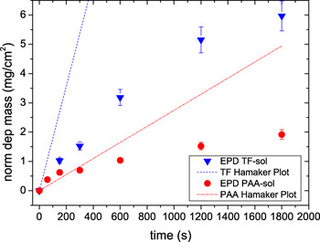
To estimate the effect of water splitting, we have compared the experimental deposited masses with the values predicted by the Hamaker law [Eq. (1)]. For the PAA-dispersion in ethanol (Fig. 5), for lower deposition times, the first part of the deposition curve is close to the curve calculated using the Hamaker law. In contrast, for the aqueous TF-sol, the deposited masses are far lower than those predicted by the Hamaker law. This can be explained because, in aqueous dispersions, a lot of charges are not used for deposition but for water splitting. For longer deposition times, a divergence in the deposited mass compared with the Hamaker law is expected because of the depletion of the TiO2 concentration in the vicinity of the working electrode and probably also because of the increasing resistivity of the deposit.
Deposition curves of the PAA-sol and the TF-sol compared with those calculated using the Hamaker law.

E. Characterization of the EPD coatings
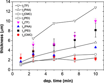
The thickness (t m in Fig. 6) was measured using an Interferometer-Profilometer for the coatings from the TF and PAA dispersions. For the coatings from the CMC and PEI dispersions, this measurement technique failed to give reliable results because the coatings were transparent. In these cases, the thickness was determined with an optical microscope.
Measured thickness t m and calculated thickness t c versus deposition time t. The thickness was measured either with an Interferometer-Profilometer (IP) or with an optical microscope (Mic) as indicated in brackets: TF (IP), PAA (IP), CMC (Mic), PEI (Mic). For explanation of the labels, refer to Table I.

Furthermore, an average thickness can be calculated from the mass of the coatings using Eq. (5), when the density and the porosity are known.
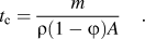 $${t_{\rm{c}}} = {m \over {\rho (1 - \varphi ){ A}}}\quad .$$
where t c is the calculated thickness (in cm), m is the deposited mass (in g), ρ is the deposit density (in g/cm3), ϕ is the porosity, and A is the coating area (in cm2).
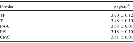
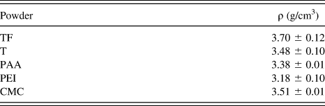
The density ρ was assumed to be the same as the density of a powder sample prepared by drying and calcinating the dispersion at 350 °C. The density of these powder samples was measured with a gas pycnometer using He (Table IV). For the porosity ϕ, we used values reported in a previous work,Reference Bleta, Alphonse and Lorenzato36 i.e., 0.5 for the TF coatings and 0.3 for the other coatings.
Densities ρ of the TiO2 powders prepared by drying and calcination of the dispersions at 350 °C.
In Fig. 6, the measured thickness t m is compared with the thickness t c calculated with Eq. (4). It can be seen that the water dispersions (TF and PEI) gave the thickest coatings (close to 10 μm for TF). For the TF coating, the thickness, determined with the interferometer, was comparable to the thickness obtained from the cross-section (Fig. 3.2). The calculated thicknesses of the TF coatings were larger than the measured values. Perhaps it is because their real porosity was lower than that estimated for calculation. To measure the real porosity by nitrogen adsorption, a much higher deposit mass would be needed. A better agreement between calculated and measured values was observed for the coatings prepared from the PAA and CMC dispersions. The coatings obtained from the T-sol have not been reported in Fig. 6 because their bad adhesion precludes thickness measurements.
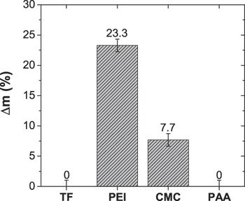
To evaluate the coating adhesion, we used a simple method, in which we measured the mass loss after dropping the samples from a height of 30 cm. From the mass difference before and after the drop, we calculated the relative mass difference Δm rel (in %), as shown in Fig. 7. Preliminary experiments with the TF dispersion have already revealed that Pluronic® F127 improves the adhesion of the deposit. This was confirmed here as the TF and PAA coatings did not lose any mass. The worst adhesion was observed for the CMC and PEI coatings. The good result with the aqueous TF-sol demonstrates that the water electrolysis, occurring during the EPD of the TF-sol, has no negative effect on the adhesion.
Adhesion test showing the relative mass difference Δm, which is the mass difference between the sample mass before and after the 30-cm drop divided by the mass of the coatings. A value of 0 indicates that no mass loss was observed during the test.

The coatings obtained from the T-sol have not been reported in Fig. 7 because their adhesion is so bad that Δm rel was close to 100%.
F. BET surface area
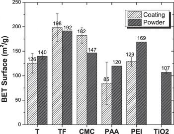
The surface area is a key parameter for catalytic applications. As the amount of coating on a substrate was very low (1–5 mg), the surface area was measured using Krypton as the adsorbate. Figure 8 shows the BET surface area of the EPD coatings compared with the BET surface area of the dried powders prepared as described in the previous paragraph.
Measured BET surface areas. Refer to Table I for explanation of the labels. For comparison, the value measured with a dispersion without additive is also shown.

The highest surface areas (180–200 m2/g) were measured for the TF and CMC coatings, whereas the lowest surface area was obtained for the PAA coatings. When we found that the surface area of the coating was lower than that of the powder, it indicates that some parts of the coating were not accessible to the adsorbate. It can be inferred that the porosity shrunk during the coating process. Conversely, when the surface area of the coating was larger than that of the powders (in the case of CMC), it can be inferred that the coating process increased the porosity. This can be due to either the formation of bubbles produced by water splitting or the presence of cracks.
IV. CONCLUSION
The best coatings on stainless steel substrates synthesized by EPD for catalytic applications were obtained from colloidal dispersions of TiO2 nanoparticles in water containing Tiron and Pluronic® F127 as additives. These coatings were homogeneous, exhibited a very good adherence on the substrate, and a large BET surface area close to 200 m2/g, which is even larger than the values obtained from equivalent powders. For a deposition time of 10 min, a thickness of 10 μm can be reached, which is perfectly appropriate for structured reactors in catalytic applications. Ethanol dispersions also gave much adhesive coatings, when PAA was used as an additive. However, the thickness was only 4 μm after 10 min of deposition, and their surface area was lower than 100 m2/g. We have shown that water splitting, occurring in the aqueous sol during EPD, led to deposited masses lower than those predicted by the Hamaker law. However, the electrolysis of water and also the small cracks, which appeared in the EPD coatings, have no negative effects on the adhesion. Small cracks could even be useful for further catalytic applications because they can increase the macroporosity and improve in that way the reactant accessibility inside the mesopores. Ongoing works are in progress to improve the understanding of the deposition mechanism.