


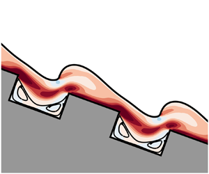



1. Introduction
The film flow along an inclined substrate is a hydrodynamic configuration encountered in numerous environmental and technological applications. Characteristic examples of the former may involve the motion of lava flows (Balmforth et al. Reference Balmforth, Craster, Rust and Sassi2006), debris flow (Allouche et al. Reference Allouche, Botton, Millet, Henry, Dagois-Bohy, Güzel and Ben Hadid2017) and biofilms (Kumar et al. Reference Kumar, Karig, Acharya, Neethirajan, Mukherjee, Retterer and Doktycz2013). Regarding technological applications, they typically involve coating in microelectronics (Stillwagon & Larson Reference Stillwagon and Larson1990; Kistler & Schweizer Reference Kistler and Schweizer1997), industrial heat and mass transfer applications (Sisoev, Matar & Lawrence Reference Sisoev, Matar and Lawrence2005; Guichet & Jouhara Reference Guichet and Jouhara2020), distillation columns (Battisti, Machado & Marangoni Reference Battisti, Machado and Marangoni2020) and falling film reactors (Yeong et al. Reference Yeong, Gavriilidis, Zapf, Kost, Hessel and Boyde2006). In practice, the substrates are frequently rough, either intentionally or accidentally, due to the presence of cavities, pillars, corrugations, or arrested particles and drops on them. The interaction between the irregularities of the topography and the fluid layer often results in a complicated nonlinear dynamical behaviour. Another significant aspect of the dynamics of the flow is the rheology of the material since, in such types of flows, the liquid may be a polymer solution or a suspension of particles which, in principle, exhibit non-Newtonian properties. The rheology of the material may considerably affect the flow, introducing interesting effects on the flow arrangement and the film shape, especially when the film exhibits viscoelastic properties. However, elastic phenomena are often overlooked since most of the existing studies consider the flow of Newtonian liquids. The understanding of the associated mechanisms and interplay of viscoelastic properties with geometrical characteristics of the substrate is of great importance since it may increase the process quality in many industrial applications.
An early attempt to study the dynamics of film flow over a variable topography was made by Pozrikidis (Reference Pozrikidis1988). He studied the two-dimensional (2-D) flow of a Newtonian liquid over a wavy wall using the boundary integral method. Moreover, Stillwagon & Larson (Reference Stillwagon and Larson1990) and Kalliadasis, Bielarz & Homsy (Reference Kalliadasis, Bielarz and Homsy2000) determined the thickness variation of the film over a trench during the spin coating process using lubrication theory and the longwave approximation, respectively. In the limit of low viscosity liquids, they found that the dynamics of the film depends on the characteristics of the obstacle, while the free surface develops a capillary ridge just before the step-down and depression before the step-up region. Later, Gaskell et al. (Reference Gaskell, Jimack, Sellier, Thompson and Wilson2004) and Veremieiev et al. (Reference Veremieiev, Thompson, Lee and Gaskell2010) extended the latter study to moderate values of fluid viscosity and surface tension by solving the inertialess 2-D Navier–Stokes equations for a film flowing over a trench. The transition to the inertia-dominated regime was studied by Bontozoglou & Serifi (Reference Bontozoglou and Serifi2008) for a Newtonian film flowing along a vertical substrate with isolated steps. They showed that the capillary ridge and depression before the step-down and step-up change their streamwise length scale when inertia is introduced in the flow. Primarily, their analysis showed that the computed streamwise length decreases with increasing flow rate. Next, Wierschem et al. (Reference Wierschem, Bontozoglou, Heining, Uecker and Aksel2008) and Nguyen & Bontozoglou (Reference Nguyen and Bontozoglou2011) solved the steady film flow over corrugated substrates with small and finite wall amplitudes, respectively. They demonstrated that resonance is possible between the undulations of the substrate and the free surface. In all the aforementioned studies, the film was considered to wet the solid structure completely. We should mention, however, that a complete wetting state cannot always be achieved, especially when the substrate is deep and aligned with the gravitational force; hence, air may be entrapped inside the topographical features (Giacomello et al. Reference Giacomello, Chinappi, Meloni and Casciola2012; Karapetsas et al. Reference Karapetsas, Lampropoulos, Dimakopoulos and Tsamopoulos2017; Pettas et al. Reference Pettas, Karapetsas, Dimakopoulos and Tsamopoulos2017; Pettas, Dimakopoulos & Tsamopoulos Reference Pettas, Dimakopoulos and Tsamopoulos2020).
Most of the studies in the literature have focused on Newtonian fluids over uneven surfaces. The first attempt to address the interaction between fluid elasticity and inertia was made by Saprykin, Koopmans & Kalliadasis (Reference Saprykin, Koopmans and Kalliadasis2007), who studied the flow over a variable topography of an Oldroyd-B fluid using lubrication theory and assuming very weak fluid elasticity. Later on, Pavlidis, Dimakopoulos & Tsamopoulos (Reference Pavlidis, Dimakopoulos and Tsamopoulos2010) and Pavlidis et al. (Reference Pavlidis, Karapetsas, Dimakopoulos and Tsamopoulos2016) solved the 2-D momentum equations for a viscoelastic film flowing over a topography featuring rectangular trenches employing the exponential Phan-Thien Tanner (ePTT) model (Phan-Thien Reference Phan-Thien1978), which introduces the most common viscoelastic properties. Recently, Pettas, Dimakopoulos & Tsamopoulos (Reference Pettas, Dimakopoulos and Tsamopoulos2020) investigated the steady flow of a polymer solution over a partially coated substrate.
However, a typical characteristic of film flows, either Newtonian or non-Newtonian, is the spontaneous appearance of wavy interfacial instabilities at the free surface if a critical volume flux is exceeded (Haar Reference Haar1965). Early efforts to investigate the flow instabilities of film over flat substrates were reported by Benjamin (Reference Benjamin1957) and Yih (Reference Yih1963). They showed that the flow first becomes unstable to longwave disturbances above a critical value of the flow rate, which depends only on the angle of inclination and fluid viscosity. Subsequent studies examined various aspects of the flow stability in both the linear and nonlinear regimes (Larson Reference Larson1992; Salamon, Armstrong & Brown Reference Salamon, Armstrong and Brown1994; Kalliadasis et al. Reference Kalliadasis, Ruyer-Quil, Scheid and Velarde2012), while some works also considered the case of surfactant-laden films (Scheid et al Reference Scheid, Oron, Colinet, Thiele and Legros2002; Bull & Grotberg Reference Bull and Grotberg2003; Karapetsas & Bontozoglou Reference Karapetsas and Bontozoglou2013, Reference Karapetsas and Bontozoglou2014). Interfacial instabilities, however, can be enhanced or mitigated by the topography of the substrate. Experimental studies on the stability of liquid films flowing over weak, periodical, rectangular trenches have demonstrated that the critical value of the flow rate is shifted to higher values as the steepness of the substrate increases (Vlachogiannis & Bontozoglou Reference Vlachogiannis and Bontozoglou2002; Argyriadi, Vlachogiannis & Bontozoglou Reference Argyriadi, Vlachogiannis and Bontozoglou2006). More recently, D'Alessio, Pascal & Jasmine (Reference D'Alessio, Pascal and Jasmine2009) examined the effects of surface tension and the presence of the bottom wall on the stability of the flow over an uneven surface. They showed that for weak to moderate surface tension, the presence of the topography tends to stabilize the flow. Trifonov (Reference Trifonov2014) performed a theoretical study by directly solving the Navier–Stokes equations while employing the Bloch–Floquet theory to account for disturbances of arbitrary wavelengths. In contrast to film flow over an inclined plane, he found that the flow is stabilized, especially under longwave disturbances. Consequently, the most critical disturbance appears to be for moderate wavenumbers.
An attempt to summarize all the above results was made by Schörner et al. (Reference Schörner, Reck, Aksel and Trifonov2018) by presenting stability maps (comparing experimental observations and theoretical predictions) in the parameter space of the inclination angle, viscosity, and corrugation amplitude and wavelength of the topography. The linear stability analysis presented by these authors also confirmed the existence of short-wave instabilities under specific values of the flow rate, in line with the experimental evidence provided earlier by Cao, Vlachogiannis & Bontozoglou (Reference Cao, Vlachogiannis and Bontozoglou2013). Schörner & Aksel (Reference Schörner and Aksel2018) were able to identify six characteristic stability map patterns that unify the linear instability of Newtonian films flowing over undulated inclines, reporting that the flow stability follows a universal pathway, which they called the ‘stability cycle’. Finally, Dauth & Aksel (Reference Dauth and Aksel2018) studied the nonlinear evolution of waves and reported wave breaking and the route to chaos (Dauth & Aksel Reference Dauth and Aksel2019).
Although a significant number of applications may involve liquids, which may be either a polymeric solution or a suspension of particles (in general, both exhibit non-Newtonian properties), all the aforementioned studies refer to Newtonian liquids. An attempt to consider non-Newtonian effects was made by Millet et al. (Reference Millet, Botton, Rousset and Ben Hadid2008) and Ruyer-Quil, Chakraborty & Dandapat (Reference Ruyer-Quil, Chakraborty and Dandapat2012), who examined the case of a liquid following a generalized Newtonian law flowing over a flat surface using the Carreau model and a modified power-law model, respectively. These studies show that shear-thinning has a destabilizing effect on the flow, while shear-thickening has the opposite effect. Recently, Allouche et al. (Reference Allouche, Botton, Millet, Henry, Dagois-Bohy, Güzel and Ben Hadid2017) confirmed the previous theoretical predictions experimentally. When it comes to the stability analysis of viscoelastic liquids, most of the studies in the literature are restricted to flows over a flat surface (Gupta Reference Gupta1967; Lai Reference Lai1967; Shaqfeh, Larson & Fredrickson Reference Shaqfeh, Larson and Fredrickson1989). The effect of substrate topography was taken into account by Davalos-Orozco (Reference Davalos-Ozorco2013), who examined the flow over a shallow corrugated wall of a viscoelastic fluid following the Oldroyd-B model. According to this study, the deformation of the free surface due to the presence of the substrate undulations may lead to stabilization by fluid elasticity. Very recently, Sharma, Ray & Papageorgiou (Reference Sharma, Ray and Papageorgiou2019), also employing lubrication theory, showed that the impact of elasticity on the stability of the inertialess flow is profoundly affected by the geometrical characteristics of the substrate. They found that as the wavelength of the periodic wall increases, the topography initially exerts a destabilizing influence, while for shorter wall-wavelengths, the topography may stabilize the flow. More recently, Pettas et al. (Reference Pettas, Karapetsas, Dimakopoulos and Tsamopoulos2019b) were able to examine the flow of a viscoelastic film (following the ePTT model) over a wavy substrate of arbitrary, but single amplitude, wavelength and inclination angle by solving the 2-D momentum conservation equations directly while employing the Bloch–Floquet theory to account for disturbances of arbitrary wavelengths. They considered both 2-D and three-dimensional (3-D) disturbances and examined the impact of the elasticity, inertia and surface tension on the stability of the flow, demonstrating the stabilizing effect of fluid elasticity. This work also demonstrated that shear-thinning, often encountered in viscoelastic liquids, has a destabilizing effect in qualitative agreement with the study of Allouche et al. (Reference Allouche, Botton, Millet, Henry, Dagois-Bohy, Güzel and Ben Hadid2017).
The main objective of the present study is to examine the dynamics and the stability of viscoelastic films flowing over a substrate featuring a periodic array of sharp rectangular trenches. This configuration has a clear advantage over previous configurations studied in the literature since, by independently varying the unit length, depth, width and inclination angle, it is possible to examine substrates with very different types of structures, i.e. ranging from substrates with wide trenches to pillared surfaces. These types of substrates are extensively studied nowadays for two main reasons: (a) they appear in electronic components, such as memory boards Stillwagon & Larson (Reference Stillwagon and Larson1990), and (b) they induce superhydrophobic properties to otherwise inert solid surfaces, reducing drag and, hence, promoting flow and surface cleaning, Cottin-Bizonne et al. (Reference Cottin-Bizonne, Barrat, Bocquet and Charlaix2009), Crowdy (Reference Crowdy2017) and Erbil (Reference Erbil2020). As will be shown below, the shape of the substrate topography, in combination with the effect of fluid elasticity, may considerably influence the stability of the flow; interestingly, it is also demonstrated that the topography shape has a non-trivial effect even on the stability of Newtonian film flows. Below, we present a detailed discussion on the mechanisms which affect the flow and provide detailed flow maps that cover a wide range of the parameter space both in terms of the liquid properties and geometrical characteristics of the substrate. To do so, we solve the 2-D steady state momentum balance equations, employing the ePTT constitutive model to account for the viscoelastic properties of the liquid, and perform a linear stability analysis of the flow subjected to 2-D disturbances; by employing the Bloch–Floquet theory, disturbances of arbitrary wavelengths (not necessarily matching the periodicity of the substrate topography) are considered.
The structure of the study is as follows: in § 2, we present the problem formulation along with the governing equations, while in § 3 we briefly describe the numerical implementation. In § 4, we initially proceed with validating our in-house model results against previous experimental observations and theoretical predictions. Next, in § 5 we present and discuss our results relating to the steady state flow patterns and the stability of the flow. Finally, we summarize our results in § 6.
2. Problem formulation
We consider the steady free-surface flow of a viscoelastic liquid over a substrate with a periodic array of rectangular trenches; a schematic is presented in figure 1. The flow is driven by gravity, while the substrate is inclined by an angle  $\alpha $. In what follows, the symbol ‘*’ and the bold variables will indicate a dimensional and a tensorial quantity, respectively. The liquid is incompressible, with constant density,
 ${\rho ^\ast }$, surface tension,
 ${\sigma ^\ast }$, relaxation time,
 $\lambda _e^\ast $ and total zero-shear viscosity,
 ${\mu ^\ast } = \mu _p^\ast + \mu _s^\ast $ where
 $\mu _p^\ast $ and
 $\mu _s^\ast $ are the polymer and the solvent viscosities, respectively. The primitive flow variable is the volumetric flow rate per unit length in the transverse direction,
 ${q^\ast }$. For the base state flow, we consider a periodic domain that consists of a single unit cell. The viscoelastic film thickness at the entrance of the periodic domain is denoted by
 ${H^\ast }$. At distance
 $L_1^\ast $ from the entrance of the unit cell, the film encounters a rectangular cavity with a width
 ${W^\ast }$ and depth,
 ${D^\ast }$, while the distance from the right end of the trench to the exit of the flow domain is denoted by
 $L_2^\ast $. The origins of the cartesian coordinate system are located at the entrance of the flow domain, with the x-axis and y-axis in the directions parallel and normal to the wall at
 $x = 0$, respectively.
Schematic of the gravity-driven, free-surface flow over a substrate with rectangular trenches inclined with respect to the horizontal by an angle  $\alpha $. Here, L* is the length of the unit cell of the periodic substrate, while
 $L_1^\ast $ and
 $L_2^\ast $ depict the inflow and outflow lengths of the corresponding unit cell. The topographical feature is characterized by a width
 ${W^\ast }$ and depth
 ${D^\ast }$ while the film height at the entrance of the domain is denoted by
 ${H^\ast }$.

Traditionally in film flows, all the lengths are scaled with the flat film thickness,  $H_N^\ast $, and all the velocity components with the mean Nusselt film velocity,
 $U_N^\ast $, defined as
 \begin{equation}H_{N}^\ast = {q^\ast }^{1/3}\; {\left( {\frac{{3{\mu^\ast }}}{{{\rho^\ast }{g^\ast }\,\textrm{sin}(a)}}} \right)^{1/3}},\quad U_N^\ast = {q^\ast }^{2/3}\; {\left( {\frac{{{\rho^\ast }{g^\ast }\,\textrm{sin}(a)}}{{3{\mu^\ast }}}} \right)^{1/3}}.\end{equation}
This scaling, for example, has been used by Pavlidis, Dimakopoulos & Tsamopoulos (Reference Pavlidis, Dimakopoulos and Tsamopoulos2010) and Pavlidis et al. (Reference Pavlidis, Karapetsas, Dimakopoulos and Tsamopoulos2016) for the study of the steady viscoelastic film flow over topography. It is apparent, however, that with the above scaling both the length and velocity scales are affected by the flowrate, see (2.1a,b). Such a dependence introduces difficulties in the interpretation of the results and, therefore, it is preferable to use an alternative scaling involving quantities that are independent of the flow rate. To do so, we introduce the capillary and viscous length scales of the liquid, respectively, defined as
 \begin{equation}l_c^\ast = {\left( {\frac{{{\sigma^\ast }}}{{{\rho^\ast }{g^\ast }}}} \right)^{1/2}},\quad l_v^\ast = {\left( {\frac{{{\mu^\ast }^2}}{{{\rho^\ast }^2{g^\ast }}}} \right)^{1/3}}.\end{equation}
Note that these lengths depend on the liquid properties, such as density, zero-shear viscosity and surface tension. The viscous length varies over a much broader range than the capillary length due to the broader variation of  ${\mu ^\ast }$, while surface tension and density of most common polymeric solutions vary over a much shorter range.
Hereafter, we scale all lengths by  $l_c^\ast $; the same choice was also made by (Trifonov Reference Trifonov2014; Pettas et al. Reference Pettas, Karapetsas, Dimakopoulos and Tsamopoulos2019a; Pettas, Dimakopoulos & Tsamopoulos Reference Pettas, Dimakopoulos and Tsamopoulos2020). By scaling all lengths by the capillary length,
 $l_c^\ast $, the dimensionless lengths of the substrate geometry become independent of the primitive flow rate. Moreover, velocities are scaled by
 $U_N^\ast $, time is scaled by
 $l_c^\ast{/}U_N^\ast $, while the pressure and stress components are scaled by the following viscous scale:
 ${\mu ^\ast }U_N^\ast{/}l_c^\ast $. Introducing the above characteristic scales, the dimensionless numbers that arise in the governing equations are the Reynolds number
 $Re$, Kapitza number
 $Ka$, elasticity number
 $El$, viscosity ratio
 $\beta $ and inclination angle
 $\alpha $; their definition is given in table 1. Since the main objective of the paper is to study the impact of the topographical irregularities on the stability of the flow, we examine cases for a constant value of the Kapitza number, i.e.
 $Ka = 2$. This particular choice of
 $Ka$ corresponds to a typical value for liquids that have been used in experiments of coating flows, e.g. solutions of polyethylene oxide (PEO) or Poly-methyl-methacrylate (PMMA) (see Bornside, Macosko & Scriven Reference Bornside, Macosko and Scriven1991; Borkar et al. Reference Borkar, Tsamopoulos, Gupta and Gupta1994; Becerra & Carvalho Reference Becerra and Carvalho2011). Note that this value of Ka corresponds to a case for which the capillary and viscous lengths are constant and equal to
 $l_c^\ast = 1.45\ \textrm{mm}$ and
 $l_v^\ast = 1.02\ \textrm{mm}$, respectively.
Dimensionless parameters and their representative values.

At this point, it is also convenient to define an additional parameter that compares the geometric characteristics of the inflow and outflow region of the unit cell with the width of the groove, named  ${T_r}$:
 \begin{equation}{T_r} = \frac{{L_1^\ast + L_2^\ast }}{{{W^\ast }}}.\end{equation}
By changing the aspect ratio,  ${T_r}$, while keeping constant the total length of the unit cell, we can study the effect of the topographical structures on the formation of the steady free surface. Two limits arise either for large or small values of
 ${T_r}$. Note that for
 ${T_r} \to \infty $ the inflow and outflow region of the domain is much larger than the trench width
 $({L_1} + {L_2} \gg W)$, and the substrate is almost flat. On the contrary, as
 ${T_r} \to 0$ the inflow and outflow regions are much smaller than the width of the groove
 $({L_1} + {L_2} \ll W)$, and the substrate tends to have a pillar-like structure.
2.1. Governing equations and boundary conditions
The governing equations of the flow are the momentum and mass conservation equations, which in the time-dependent dimensionless form are
 \begin{equation}\begin{array}{l} Re\,C{a^{ - 1/2}}{\left( {\dfrac{{\textrm{sin}\,a}}{3}} \right)^{1/2}}\left( {\; \dfrac{{\partial \boldsymbol{u}}}{{\partial t}} + (\boldsymbol{u} - {\boldsymbol{u}_m})\boldsymbol{\cdot }\boldsymbol{\nabla }\boldsymbol{u}} \right) + \boldsymbol{\nabla }P - \boldsymbol{\nabla }\boldsymbol{\cdot }\boldsymbol{\tau } - C{a^{ - 1}}\boldsymbol{g} = 0,\\ \end{array}\end{equation}
 \begin{equation}\boldsymbol{\nabla }\boldsymbol{\cdot }\boldsymbol{u} = 0.\end{equation}
Here,  $\boldsymbol{u} = {({u_x},{u_y})^\textrm{T}}$, P,
 $\boldsymbol{\tau }$ denote the velocity, pressure and stress fields on the flow domain, respectively;
 $\boldsymbol{\nabla } = {({\partial _x},{\partial _y})^\textrm{T}}$ denotes the gradient operator for a cartesian coordinate system, while
 ${\boldsymbol{u}_m} = \partial \boldsymbol{x}/\partial t$ denotes the velocity of the mesh nodes, and
 $g = {(\textrm{sin}\,\alpha , - \textrm{cos}\,\alpha )^\textrm{T}}$ is the unit vector in the direction of gravity. The capillary number,
 $Ca = {\mu ^\ast }U_N^\ast{/}\sigma $, which arises in the above equation is not an independent variable, but is related to the previously defined dimensionless quantities via the expression
 \begin{equation}Ca = K{a^{ - 1}}R{e^{2/3}}\; {\left( {\frac{{\textrm{sin}\,a}}{3}} \right)^{1/3}}.\end{equation}
The extra stress tensor,  $\boldsymbol{\tau }$, is split into a purely Newtonian part and a polymeric contribution,
 ${\boldsymbol{\tau }_p}$, defined as
 \begin{equation}\boldsymbol{\tau } = 2\beta \dot{\boldsymbol{\gamma }} + {\boldsymbol{\tau }_p},\end{equation}
where  $\dot{\boldsymbol{\gamma }} = (\boldsymbol{\nabla }\boldsymbol{u} + \boldsymbol{\nabla }{\boldsymbol{u}^\textrm{T}})/2$ is the rate of strain.
To account for the viscoelasticity of the material, we use the affine exponential model by Phan-Thien and Tanner (ePTT) (Phan-Thien Reference Phan-Thien1978):
 \begin{gather}Y({\boldsymbol{\tau
}_p}){\boldsymbol{\tau }_p} + Wi\; {\mathop{\boldsymbol{\tau
}}\limits^{\nabla}}_{p} - 2(1 - \beta )\dot{\boldsymbol{\gamma
}} = 0,\quad Y({\boldsymbol{\tau }_p}) := \textrm{exp}\left(
{\frac{\varepsilon }{{1 - \beta }}\;
Wi\,\textrm{trace}({\boldsymbol{\tau }_p})}
\right),\end{gather}
 \begin{gather}{\mathop {\boldsymbol{\tau
}}\limits^{\nabla}}_{p} := \frac{{\partial {\boldsymbol{\tau
}_{\boldsymbol{p}}}}}{{\partial t\; }} + (\boldsymbol{u} -
{\boldsymbol{u}_m})\boldsymbol{\cdot }\boldsymbol{\nabla
}{\boldsymbol{\tau }_p} - [{\boldsymbol{\tau
}_p}\boldsymbol{\cdot }\boldsymbol{\nabla }\boldsymbol{u} +
{({\boldsymbol{\tau }_p}\boldsymbol{\cdot
}\boldsymbol{\nabla
}\boldsymbol{u})^\textrm{T}}],\end{gather}
where  $Wi = \lambda _e^\ast {U_N}/l_c^\ast $ is the Weissenberg number. Wi can be expressed as a function of the elasticity number El, i.e.
 $Wi = El\,K{a^{1/2}}Ca$. Note that the elasticity number, El, as defined in table 1, denotes the ratio of the relaxation time of the polymeric solution with the viscous timescale,
 $t_v^\ast = {({\mu ^\ast }/{\rho ^\ast }{g^{{\ast} 2}})^{1/3}}$. For our parametric study, it is preferable to use the elasticity number, instead of Wi, since El depends only on material properties – the relaxation time, zero-shear viscosity and liquid density – which facilitates direct comparison with experiments; whereas Wi depends on the volumetric flow rate and, hence, on Re, see relevant discussion in Pettas et al. (Reference Pettas, Karapetsas, Dimakopoulos and Tsamopoulos2019b). Finite values of the parameter
 $\varepsilon $ set an upper limit to the elongational viscosity, which increases as the parameter decreases, while it introduces elongational and shear thinning to the fluid model. The ePTT model is reduced to the Oldroyd-B model by setting the value of the parameter
 $\varepsilon $ equal to zero and to the Upper Convective Maxwell model by additionally setting
 $\beta $ equal to zero.
Accounting for the boundary conditions, along the free surface of the film, a local interface force balance is imposed between the normal stress and capillary forces,
 \begin{equation}\boldsymbol{n}\boldsymbol{\cdot }( - P\boldsymbol{I} + \boldsymbol{\tau }) ={-} {P_{air}}\boldsymbol{n} + C{a^{ - 1}}\; \frac{{\textrm{d}\boldsymbol{t}}}{{\textrm{d}s}},\end{equation}
where  $\boldsymbol{n}$ is the outward unit vector to the free surfaces and
 $\boldsymbol{t}$ is the unit tangent vector pointing in the clockwise direction (see Ruschak Reference Ruschak1980). Note that the air in contact with the interface is at the ambient air pressure, which is set equal to zero,
 ${P_{air}} = 0$. Also, the interfaces obey the kinematic condition
 \begin{equation}\boldsymbol{n}\boldsymbol{\cdot }(\boldsymbol{u} - {\boldsymbol{u}_m}) = 0,\end{equation}
while along the walls of the substrate, we impose the usual no-slip, no-penetration boundary conditions. Moreover, at the inflow and the outflow of the unit cell, periodic boundary conditions are employed. Note that for the purposes of the present study, we assume that the steady flow has the same periodicity as the substrate structure (i.e. we assume that the steady solution is L-periodic),
 \begin{equation}\boldsymbol{u}{|_{x = 0}} = \boldsymbol{u}{|_{x = L}},\end{equation}
 \begin{equation}\boldsymbol{n}\boldsymbol{\cdot }( - P\boldsymbol{I} + \boldsymbol{\tau }){|_{x = 0}} = \boldsymbol{n}\boldsymbol{\cdot }( - P\boldsymbol{I} + \boldsymbol{\tau }){|_{x = L}},\end{equation}
The remaining degree of freedom, the film height at the entrance of the unit cell  ${H^\ast }$, is determined by requiring that the dimensionless flow rate is equal to unity:
 \begin{equation}q: = \int_0^{{H^\ast }/l_c^\ast } {{u_x}\,\textrm{d}y} = 1.\end{equation}
3. Numerical Implementation
3.1. Base state – steady state solution
The base flow is steady, 2-D and is assumed to be L-periodic. In order to solve the above set of equations at steady state numerically, we employ the mixed finite element/Galerkin method (Pettas et al. Reference Pettas, Karapetsas, Dimakopoulos and Tsamopoulos2015; Pavlidis et al. Reference Pavlidis, Karapetsas, Dimakopoulos and Tsamopoulos2016) along with an elliptic grid generation scheme (Dimakopoulos & Tsamopoulos Reference Dimakopoulos and Tsamopoulos2003; Chatzidai et al. Reference Chatzidai, Giannousakis, Dimakopoulos and Tsamopoulos2009) to account for the free surface deformation. The corresponding weak formulation of the governing equations is presented in detail in the Appendix of Pettas et al. (Reference Pettas, Karapetsas, Dimakopoulos and Tsamopoulos2019a). Moreover, to trace the steady-state solution in parameter space, a pseudo-arc-length continuation is incorporated as part of the solution of the finite element code (see Pettas et al. Reference Pettas, Karapetsas, Dimakopoulos and Tsamopoulos2017; Varchanis, Dimakopoulos & Tsamopoulos Reference Varchanis, Dimakopoulos and Tsamopoulos2017).
3.2. Linear stability analysis
We consider the stability of this steady flow subjected to infinitesimal 2-D perturbations. To account for the perturbed physical domain (x, y), we map it to a known reference domain (η, ξ). The variables are written in the computational domain and are decomposed into a part which corresponds to the base state solution and an infinitesimal disturbance using the following ansatz:
 \begin{equation}\left[ {\begin{array}{@{}c@{}} \boldsymbol{u}\\ {\begin{array}{@{}c@{}} P\\ {\begin{array}{@{}c@{}} \boldsymbol{G}\\ {\begin{array}{@{}c@{}} {{\boldsymbol{\tau }_p}}\\ \boldsymbol{x} \end{array}} \end{array}} \end{array}} \end{array}} \right](\eta ,\xi ,t) = \left[ {\begin{array}{@{}c@{}} {{\boldsymbol{u}_b}}\\ {\begin{array}{@{}c@{}} {{P_b}}\\ {\begin{array}{@{}c@{}} {{\boldsymbol{G}_b}}\\ {\begin{array}{@{}c@{}} {{\boldsymbol{\tau }_{p,b}}}\\ {{\boldsymbol{x}_b}} \end{array}} \end{array}} \end{array}} \end{array}} \right](\eta ,\xi ) + \delta \left[ {\begin{array}{@{}c@{}} {{\boldsymbol{u}_d}}\\ {\begin{array}{@{}c@{}} {{P_d}}\\ {\begin{array}{@{}c@{}} {{\boldsymbol{G}_d}}\\ {\begin{array}{@{}c@{}} {{\boldsymbol{\tau }_{p,d}}}\\ {{\boldsymbol{x}_d}} \end{array}} \end{array}} \end{array}} \end{array}} \right](\eta ,\xi )\,{\textrm{e}^{\lambda t}}.\end{equation}
The first terms on the right-hand side of these equations represent the steady state solution, indicated by the subscript ‘b’, while the second ones are the perturbation. The subscript ‘d’ corresponds to the spatial variation of the disturbance while  $\delta \ll 1$; the
 ${\boldsymbol{x}_d}$ is the disturbance of the position vector. According to our ansatz, an exponential dependence on time is assumed; here, λ denotes the growth rate. If the calculated λ turns out to have a positive real part, the disturbance grows with time, and therefore the corresponding steady state is considered unstable. Introducing the expression (3.1) in the weak formulation of the time-dependent governing equations and the corresponding boundary conditions (2.4)–(2.11), and neglecting terms of order higher than the first in the perturbation parameter
 $\delta $, the linearized equations are derived; a detailed description is provided in appendix A of Pettas et al. (Reference Pettas, Karapetsas, Dimakopoulos and Tsamopoulos2019b).
3.3. Periodic boundary conditions and implementation of Floquet–Bloch theory
For flows over periodically structured surfaces, the most unstable disturbance may have a wavelength that exceeds the period of the domain. Thus, it becomes evident that if one assumes periodic conditions for the disturbances between the inflow and outflow boundaries, the overall linear stability of the system cannot be captured unless a sufficiently long computational domain is considered. This would imply a formidable computational cost in the case where longwave disturbances are the most unstable ones, as is typical for thin-film flows. As we will discuss below, the most appropriate and efficient way to deal with this issue is to employ the Floquet–Bloch theory, which allows us to model the flow over a structured surface by considering the small periodic domain of the topography. This accomplishes a considerable reduction to the computational cost, while examining disturbances with wavelengths that may extend over multiple trenches or fractions thereof. According to Bloch's theorem (Pain Reference Pain2008), it is sufficient to look for solutions such that the disturbances between the inflow and outflow of the unit cell are related to each other with the following expression:
 \begin{equation}{\left. {\left[ {\begin{array}{@{}c@{}} {{\boldsymbol{u}_d}}\\ {\begin{array}{@{}c@{}} {{P_d}}\\ {\begin{array}{@{}c@{}} {{\boldsymbol{G}_d}}\\ {\begin{array}{@{}c@{}} {{\boldsymbol{\tau }_{p,d}}}\\ {{y_d}} \end{array}} \end{array}} \end{array}} \end{array}} \right]} \right|_{x = 0}} = {\left. {\left[ {\begin{array}{@{}c@{}} {{\boldsymbol{u}_d}}\\ {\begin{array}{@{}c@{}} {{P_d}}\\ {\begin{array}{@{}c@{}} {{\boldsymbol{G}_d}}\\ {\begin{array}{@{}c@{}} {{\boldsymbol{\tau }_{p,d}}}\\ {{y_d}} \end{array}} \end{array}} \end{array}} \end{array}} \right]} \right|_{x = L}}\,{\textrm{e}^{2\mathrm{\pi }Q\textrm{i}}}.\end{equation}
Using this formulation, the unknown disturbances  $({\boldsymbol{u}_d},{P_d},{\boldsymbol{G}_d},{\boldsymbol{\tau }_{p,d}},{y_d})$ will be determined by imposing (3.2) at the edges of the periodic domain, ensuring that for finite real values of Q, the disturbances will not be L-periodic. It may be shown that it is sufficient to examine the values of
 $Q \in [0,0.5]$ (Pettas et al. Reference Pettas, Karapetsas, Dimakopoulos and Tsamopoulos2019b). For example, when
 $Q = 0.5$, the imposed perturbation has a wavelength that is twice the size of the physical domain, whereas
 $Q \to 0$ corresponds to disturbances with wavelength much larger than the size of the periodic domain. Disturbances with
 $Q = 0$ should be distinguished, since in that case (3.2) reduces to typical periodic boundary conditions. Thus, this case corresponds to disturbances that have the same period or aliquots of the basic solution, i.e. correspond to superharmonic instabilities.
3.4. The Arnoldi algorithm
After we discretize the linearized set of equations, we end up with a generalized eigenvalue problem of the form
 \begin{equation}\boldsymbol{Aw} = \lambda \; \boldsymbol{Mw},\end{equation}
where  $\boldsymbol{A}$ and
 $\boldsymbol{M}$ are the Jacobian and the mass matrix, respectively, with
 $\lambda $ the eigenvalues and
 $\boldsymbol{w}$ the corresponding eigenvectors. This eigenvalue problem is solved using Arnoldi's method combined with the shift-and-invert transformation, which allows us to locate only the eigenvalues of interest; for determining critical conditions, we need those eigenvalues with the smallest real part (Christodoulou Reference Christodoulou1990; Natarajan Reference Natarajan1992; Karapetsas & Tsamopoulos Reference Karapetsas and Tsamopoulos2013; Pettas et al. Reference Pettas, Karapetsas, Dimakopoulos and Tsamopoulos2015). According to our framework, the solution is stable if the real parts of all eigenvalues are less than or equal to zero for all values of Q. To implement Arnoldi's algorithm, we use the public domain code ARPACK (Lehoucq, Sorensen & Yang Reference Lehoucq, Sorensen and Yang1997), while the accuracy of the converged eigenpairs is independently checked by evaluating the residual
 $|{\boldsymbol{Aw} - \lambda \; \boldsymbol{Mw}} |$, and this quantity is always less than 10−12 for the reported results.
4. Validation
The accuracy of our numerical results is verified by examining their convergence with mesh refinement. Since the sharp changes of the topography and particularly the sharp corners in viscoelastic flows may give rise to singularities (see Karapetsas & Tsamopoulos Reference Karapetsas and Tsamopoulos2013; Pettas et al. Reference Pettas, Karapetsas, Dimakopoulos and Tsamopoulos2015), they may strongly influence the flow. Hence, we have performed a detailed mesh convergence study focusing οn these areas to identify the most suitable mesh to use in our calculations. Moreover, although we had no numerical difficulties with keeping the corners sharp, we have examined the possible influence on the flow of turning them to circular sections, because this is often reported in the literature (see Schörner et al. Reference Schörner, Reck, Aksel and Trifonov2018). When the local radius of curvature was up to dimensionless 0.1, we observed no effect on the solution. All these tests are reported in the Appendix.
Before we proceed with the discussion of our results, we present a series of validation tests of our in-house code with experimental observations and theoretical predictions for relevant flows found in the literature. To this end, we have examined the stability of Newtonian films over substrates with rectangular trenches subjected to 2-D disturbances, and we present in figure 2 the theoretical and experimental data for two different liquids, Elbesil 100 and Elbesil 145, the properties of which are given in table 2.
Comparison of the predicted neutral curves with previous numerical and experimental studies. The liquids that have been used are (a) Elbesil 100 and (b) Elbesil 145 (see table 2); the inclination angle is  $a = 10^\circ $ and the geometric parameters are
 ${T_r} = 0.05$,
 $D = 5.506$. In panels (a) and (b), the length of the unit cell is
 $L = 13.765$ and 20.648
 $({L_1} = {L_2} = 0.05)$, respectively. The orange dashed lines and the cyan dots indicate the theoretical analysis and the experimental data, respectively, of Schörner et al. (Reference Schörner, Reck, Aksel and Trifonov2018). Finally, the continuous black lines correspond to our study.

Newtonian fluids and their properties that are used for validation.

In figure 2 we present the dependence of the critical  $R{e_c}$ on the frequency of the instability. According to our formulation, the dimensional frequency is related to the imaginary part of the eigenmode via the following expression:
 \begin{equation}{f^{\ast}} = \frac{{Imag(\lambda )}}{{2\pi }}\frac{{U_N^{\ast} }}{{l_c^{\ast} \; }} = \frac{{Imag(\lambda )}}{{2\pi }}K{a^{1/2}}Ca\,t{_v^{\ast - 1}}.\end{equation}
By scaling the dimensional frequency with  $t{_v^{\ast - 1}}$ the dimensionless frequency is given by the following expression:
 \begin{equation}f = \frac{{Imag(\lambda )}}{{2\pi }}K{a^{1/2}}Ca.\end{equation}
We present in figure 2 the stability maps obtained both theoretically and experimentally by Schörner et al. (Reference Schörner, Reck, Aksel and Trifonov2018) along with our numerical predictions (shown with the continuous black line) for Elbesil 100 (see figure 2a) and Elbesil 145 (see figure 2b) for  $L = 13.765$ and 20.648, respectively. In both cases, our predictions are in excellent agreement with theoretical and experimental results found in the literature. We note, though, that there is a slight deviation between our theoretical analysis and that of Schörner et al. (Reference Schörner, Reck, Aksel and Trifonov2018) (which is more obvious in figure 2b) due to the different details of the considered substrate. In our case, we have used a topography with sharp edges, as in the experimental structure, while Schörner et al. (Reference Schörner, Reck, Aksel and Trifonov2018) considered smoothed rectangular trenches for their theoretical analysis. Interestingly, our predictions are closer to the experimental observations, underlining the relative importance of the different shape of the topography on the stability of the film.
Interestingly, above a specific value of Re, the experimental observations deviate from the theoretical results, see figure 2(b) for  $Re \gt 12$. At this point, we should mention that there is no guarantee that all base flow formations in this particular experiment correspond to the steady state solution considered in the theoretical model. We speculate though that thick films may have different flow arrangements (i.e. L-periodicity of the steady fluid flow may have broken down). Our hypothesis is reinforced by the study of Tseluiko, Blyth & Papageorgiou (Reference Tseluiko, Blyth and Papageorgiou2013), who observed that the film flow might experience a sequence of multiple steady states where the solution may, in general, not be L-periodic.
5. Results and discussion
Numerical solutions were obtained over a wide range of parameter values. The ‘base’ case, however, has typical dimensional values of  $L = 20$,
 ${L_1} = {L_2} = 5$,
 $\; W = 10$ and
 $D = 5$; from (2.3), assuming the above geometrical characteristics, it is also derived that
 ${T_r} = 1$. This set of parameters will be kept constant throughout the paper unless stated otherwise.
5.1. Steady state
We start with a brief discussion of the steady state solution. As mentioned above, a detailed discussion of this problem has been presented by Pavlidis, Dimakopoulos & Tsamopoulos (Reference Pavlidis, Dimakopoulos and Tsamopoulos2010) and Pavlidis et al. (Reference Pavlidis, Karapetsas, Dimakopoulos and Tsamopoulos2016). It is important to note, though, that these authors have used a different scaling (i.e. based on the film thickness); therefore, we find that it will be useful to briefly discuss the results in the light of the scaling employed herein (i.e. based on the capillary length scale), which may also provide new insight. Moreover, we will focus on cases with unit cells of considerably smaller length than the ones examined by Pavlidis, Dimakopoulos & Tsamopoulos (Reference Pavlidis, Dimakopoulos and Tsamopoulos2010) and Pavlidis et al. (Reference Pavlidis, Karapetsas, Dimakopoulos and Tsamopoulos2016), making the surface tension effects more prominent.
In figure 3, we consider a substrate with  $L = 20$,
 ${T_r} = 1$ and
 $D = 5$ and present the streamline pattern for an Oldroyd-B liquid
 $(\varepsilon = 0)$. As representative values, we choose
 $Ka = 2$ and
 $El = 3$ since in coating applications, the flowing materials typically have a high viscosity
 $(Ka \lt 6)$ and short relaxation time (Borkar et al. Reference Borkar, Tsamopoulos, Gupta and Gupta1994; Becerra & Carvalho Reference Becerra and Carvalho2011); the ratio of the Newtonian solvent viscosity over the total zero shear viscosity is
 $\beta = 0.10$, and the angle of inclination is
 $\alpha = 10^\circ$. Moreover, figure 3(a–d) shows the streamline pattern of the flow for different values of
 $Re = 3,8,12,30$, respectively. As Nguyen & Bontozoglou (Reference Nguyen and Bontozoglou2011) described in a Newtonian liquid, many characteristics of the flow field can be explained by considering the flow as ballistic flow, where the ejection platform for the fluid is the flat part of the substrate at the inflow. The magnitude of Re determines the distance the fluid can travel before it ‘lands’ somewhere inside the cavity.
Steady states of the film flow over the substrate for (a)  $Re = 3$, (b)
 $Re = 8$, (c)
 $Re = 12$ and (d)
 $Re = 30$. The liquid parameters are
 $Ka = 2$,
 $El = 3$,
 $\beta = 0.10$, for an Oldroyd-B fluid while the geometrical characteristics of the substrate are
 $L = 20$,
 ${T_r} = 1$ and
 $D = 5$. The inclination angle is
 $\alpha = 10^\circ $.

Starting with figure 3(a), low values of Re correspond to thin films, while the streamlines and the film shape depict that the fluid lands closer to the upstream wall. Hence, a local minimum is formed at the free surface while a vortex arises at the upstream concave corner of the substrate. Increasing the flow rate to moderate values, see figure 3(b,c), the injected liquid impacts the liquid ahead and with the aid of elasticity, causing the formation of a cusp. This is clearly a non-Newtonian effect since in the case of Newtonian liquids, the interface remains smooth for all values of Re and can be attributed to the fluid elasticity. With increasing inertia, the two recirculation regions expand and merge into one large eddy inside the cavity. For very large values of Re, inertia prevails, and the film surpasses the trench without significant redirection of the flow, figure 3(d). After that point, the free surface deformations decrease due to the increased film thickness, while the eddy expands and occupies the entire area of the groove.
5.1.1. Effect of elasticity
The impact of the elasticity in the flow arrangement is apparent when we examine its effect on the amplitude of the free-surface deformation, A, which can be defined as
 \begin{equation}A = \frac{{H_{max}^\ast{-} H_{min}^\ast }}{2}.\end{equation}
In figure 4(a), we present the dependence of A on Re for polymer solutions that exhibit various relaxation times (El changes). For low values of the flowrate  $(Re \to 0)$, the deformation of the free surface was calculated to be
 $A \approx 0.57$ for all values of El. Hence, in the absence of inertia, the film closely follows the shape of the wall, whereas the viscoelastic effects become negligible. In the opposite limit, at high values of the Reynolds number, the film succeeds in surpassing the topographical structures, and the shape of the steady free surface tends to acquire a planar shape, since the liquid near the interface does not feel the presence of the substrate topography. However, at moderate values of Re
 $(3 \lt Re \lt 20)$, the presence of the substrate structure along with the interplay between the inertia, gravity and surface tension causes a prominent rise in the amplitude of the free surface deformation. This effect is often referred to as ‘resonance’ in the literature (Bontozoglou & Papapolymerou Reference Bontozoglou and Papapolymerou1998; Wierschem & Aksel Reference Wierschem and Aksel2004), while it was experimentally validated by Vlachogiannis and Bontozoglou (Reference Vlachogiannis and Bontozoglou2002) and Argyriadi, Vlachogiannis & Bontozoglou (Reference Argyriadi, Vlachogiannis and Bontozoglou2006). This is an outcome of the interaction between the reflected wave of the free surface and the capillary waves that travel in the upstream direction of the flow. The point of resonance corresponds to a specific value of the Reynolds number,
 $R{e_{res}}$, for which the surface velocity of the fluid is equal to the phase velocity of the capillary waves. In the case of a Newtonian liquid, which is depicted by the black dashed line in figure 4(a), the resonance point arises at
 $Re = 10.4$, where the amplitude of the free surface deformation obtains its maximum value, 0.98.
(a) Amplitude of the free surface, A, as a function of the Reynolds number for various values of El while the dashed black line indicates the case of a Newtonian liquid. (b,c) Film shape and spatial variation of normal stress component,  ${\tau _{p,xx}}$, for
 $El = 1$ and
 $El = 2$, respectively, and the same Reynolds number,
 $Re = 14$. The remaining parameters are
 $Ka = 2$,
 $\varepsilon = 0$ and
 $\beta = 0.10$. The inclination angle
 $\alpha = 10^\circ $.

Increasing the elasticity number, the amplitude of the free surface is not affected either for  $Re \to 0$ or high values of Re. Nevertheless, for small values of Re even a small amount of elasticity leads to the decrease of A since the bulk elasticity of the fluid resists the deformation imposed by the solid wall. Therefore, the amplitude of the free surface decreases up to
 $Re \approx 3.5$. For moderate values of Re, the elasticity has the opposite effect and tends to amplify the free surface deformation. As shown in figure 4(a), on increasing El, the maximum amplitude of the free surface increases considerably (for
 $El = 1,2,3$ the maximum value of A is
 $0.98,1.38,1.67$, respectively).
We note, though, that elasticity shifts  $R{e_{res}}$ to higher values, which can be attributed to some extent to fluid elasticity generating a force that opposes the effect of inertia. To rationalize this mechanism, it is convenient to describe the relevant mechanisms in terms of a single viscoelastic fluid parcel of constant volume. Note that a viscoelastic fluid parcel can undergo all rearrangements of a Newtonian one – translation, rotation and stretching – but exhibits stronger resistance to the last of these, which is dictated by the presence of the viscoelastic stresses. Besides, the presence of the stress gradients that are generated by the substrate morphology force it to be extended or compressed in the direction of the flow, while the value of
 ${\tau _{p,xx}}$ is a measure of that stretching. Consequently, the fluid parcel is stretched in the upstream corner
 $({\tau _{p,xx}} \gt 0)$ and compressed at the downstream corner
 $({\tau _{p,xx}} \lt 0)$, see figure 4(b,c). For moderate values of Re it undergoes a ballistic trajectory, while the magnitude of Re determines the distance it can travel before it ‘lands’ somewhere inside the cavity. Simultaneously, the build-up of viscoelastic stress gradients at the upstream convex corner tries to prevent this movement.
The elongation of the fluid parcel in the x-direction by the  $xx$-stress gradients causes additional shrinkage in the y-direction, via volume preservation. As a result,
 ${\tau _{p,yy}}$ obtains negative values in the upstream convex corner of the trench, see figure 5(a,b). The stress variation in the y-direction will decrease the height of the free surface locally. On the contrary, at the downstream convex corner, the fluid parcel is squeezed, resulting in positive values of
 ${\tau _{p,yy}}$ with the additional pushing the free surface to increase the hump, as shown in figure 3.
Film shape and spatial variation of the normal stress component,  ${\tau _{p,yy}}$, for (a)
 $El = 1$ and (b)
 $El = 2.0$ at
 $Re = 14$. The remaining parameters are
 $Ka = 2$,
 $\varepsilon = 0$, and
 $\beta = 0.10$. The inclination angle
 $\alpha = 10^\circ $.

5.1.2. Effect of the topography
Next, we examine the impact of the geometrical characteristics of the substrate on the deformation of the free surface. In figure 6(a) we present the amplitude of the steady free-surface distortions as a function of Re for various values of D. For shallow trenches (D = 1), the free surface acquires a smoother shape since the film easily surpasses the cavities of the periodic topography, see figure 6(b). With increasing depth of the trench, the amplitude of the free-surface deformation increases considerably, since it becomes more difficult for the film to surpass the step-up region and therefore gives rise to a more prominent static hump near the downstream wall, see figure 6(c). Interestingly, for large trench depths  $(D \ge 3)$ the dependence of A on Re remains unaffected; in figure 6(a), the curves for
 $D = 5$ and 7 are almost identical. Clearly, beyond some critical value of D the amplitude of the free surface deformations is independent of the depth of the topographical features. When the structures are deep, the mainstream region of the film does not feel the presence of the bottom wall, i.e. the generation of the eddy in the midplane smooths out the wall structure. Thus, the existence of the recirculation also provides a limitation, to some extent, to the effect of elasticity for trenches with large depths.
(a) Relative amplitude of the free surface, A, as a function of the Reynolds number for  $D = 1$ (red),
 $D = 2$ (green),
 $D = 5$ (blue) and
 $D = 7$ (orange). (b,c) Spatial variation of normal stress component,
 ${\tau _{p,xx}}$ and the streamline pattern for
 $D = 1$
 $(Re = 11.8)$ and
 $D = 7$
 $(Re = 13.8)$, respectively. The remaining parameters are
 $Ka = 2$,
 $El = 3$,
 $\varepsilon = 0.0$,
 $\beta = 0.10$ and
 $\alpha = 10^\circ $.

Another significant factor that affects the steady film formation is the shape and the size of the topographical structure. In figure 7(a), we present the amplitude of the free surface deformation as a function of Re for different types of topographical features. To this end, we keep the length of the unit cell  $(L = 20)$ constant, and vary the aspect ratio,
 ${T_r}$, as defined in (2.3). High values of
 ${T_r}$ correspond to cases where the inflow and outflow region of the domain is much larger than the trench width (e.g. see figure 7b), whereas low values of
 ${T_r}$ correspond to cases with pillar-like structures (e.g. see figure 7c). As shown in figure 7(a), for
 ${T_r} = 4$, the free surface is relatively smooth even at the peak of the resonance. For such high values of
 ${T_r}$, the size of the trench is relatively small with respect to the rest of the substrate, and the film flow tends to the simple Nusselt flow limit. Figure 7(b) depicts the film shape and the spatial variation of the normal stress component for
 ${T_r} = 4$ and
 $Re = 11.8$; this value of Re corresponds to the case with maximum deformation. Clearly, the film surpasses the cavity easily with very little interfacial deformation and a low level of stresses in the cavity; the picture remains almost the same over the entire range of Re.
(a) Relative amplitude of the free surface, A, as a function of the Reynolds number for various values of  ${T_r}$. (b,c) Film shape and spatial variation of normal stress component,
 ${\tau _{p,xx}}$, for
 ${T_r} = 4$ and
 ${T_r} = 0.10$ for
 $Re = 11.8$ and
 $Re = 17.6$, respectively. The remaining parameters are
 $Ka = 2$,
 $El = 3$,
 $\varepsilon = 0.0$,
 $\beta = 0.10$ and
 $\alpha = 10^\circ $.

On decreasing the value of  ${T_r}$, the relative width of the cavity increases. As a result, the redirection of the flow is inevitable, with more fluid going through the cavity. Therefore, the resonance of the free surface with the bottom undulations becomes stronger, resulting in a considerable increase of the maximum interfacial deformation. As depicted in figure 7(a), the amplitude of the free surface deformation at the resonance point is inversely proportional to
 ${T_r}$. For
 ${T_r} = 0.10$, A is found to be equal to 2.23. Also, for this particular case, we observe a change in the slope of A for
 $Re \approx 11$. As showed by Pettas et al. (Reference Pettas, Karapetsas, Dimakopoulos and Tsamopoulos2019a), the latter phenomenon is connected with a new resonance point related to the cusp formation at the steady free surface. For
 ${T_r} = 0.1$ (see figure 7c), the maximum normal polymeric stress field arises at the inflow and outflow regions of the unit cell where the polymeric chains are squeezed to conform with the fluid flow arrangement, while residual stresses are convected from one unit cell to the other producing a stronger polymeric stress field. Therefore, the elastic phenomena are more prominent, resulting in amplification of the free-surface deformation.
5.2. Linear stability
So far, we have investigated the impact of non-Newtonian properties on the steady free-surface formation. In this section, we will discuss the stability of the steady flow subjected to infinitesimal, 2-D disturbances. Since much of the work in the literature has focused on the stability of flow under longwave disturbances and to provide the proper context, we will briefly discuss the predictions of our model for  $Q \to 0$. Then we will proceed with the discussion of the linear stability for disturbances with arbitrary wavelengths. Our analysis is focused mainly on the stability of an Oldroyd-B fluid, whereas in the last subsection, we will investigate the effect of varying shear and extensional viscosity in the flow stability by employing the ePTT constitutive model.
5.2.1. Longwave disturbances
We begin our discussion by examining the stability of the steady flow when subjected to longwave disturbances. To this end, we focus on disturbances with Bloch wave number  $Q = {10^{ - 2}}$. In figure 8(a), we depict the critical value of the Reynolds number as a function of the trench depth, D, for three different values of the elasticity number, El. The black dashed line corresponds to the case of a Newtonian liquid
 $(El = 0)$, while the dashed blue and the solid red lines represent the critical conditions for
 $El = 1$ and 2, respectively; the shaded area corresponds to the unstable flow regime, where at least one eigenmode has a positive real part. All curves in this figure exhibit two limits, one for
 $D \to 0$ and another for
 $D \gg 1$. In the former case, the topography approaches the case of a flat plane and the flow field resembles the Nusselt type of flow, while the critical value of Re for instability can be derived from the following expression in the case of an Oldroyd-B fluid (Lai Reference Lai1967):
 \begin{equation}R{e_c} = \tfrac{5}{6}\textrm{cot}\,\alpha - \tfrac{5}{2}Wi(1 - \beta ).\end{equation}
Clearly, for  $D \to 0$, both elasticity and inertia are destabilizing. The predicted values from (5.2) appear in figure 8(a) as points (
 ) and are in perfect agreement with our calculations. As discussed by Sharma, Ray & Papageorgiou (Reference Sharma, Ray and Papageorgiou2019) and Huang & Khomami (Reference Huang and Khomami2001) for viscoelastic film flow over flat substrates, due to the effect of normal stresses in the disturbed flow, elasticity ‘pushes’ the fluid in the streamwise direction towards local maxima of the film thickness and away from local minima.
(a) Critical Re as a function of depth for  $Q = {10^{ - 2}}$ and (b) penetrated volume as a function of depth calculated at
 $Re = 5$ for
 $El = 0,\;1,\;2$. The marks
 represent the analytical predictions of (5.2). The remaining parameters are
 $Ka = 2$,
 $\varepsilon = 0$ and
 $\beta = 0.10$. The inclination angle is
 $\alpha = 10^\circ $.

As depicted in figure 8(a), for Newtonian liquids and relatively shallow structures (for  $D \lt 3$), the flow field deviates from the typical Nusselt limit and the topography appears to stabilize the flow; the stabilizing effect of shallow structures on the film flow is well known and has been reported in previous works for the case of Newtonian flows (Kalliadasis & Homsy Reference Kalliadasis and Homsy2001). Interestingly, though, deeper structures result in the decrease of
 $R{e_c}$ indicating destabilization of the flow. A critical point of depth,
 $D \approx 3$, arises at which
 $R{e_c}$ reaches a maximum value.
In order to rationalize this behaviour (i.e. the non-monotonic dependence of  $R{e_c}$ on the trench depth even for Newtonian liquids), it is important to understand how the depth of the trench may affect the flow inside the cavity. To this end, we evaluate in figure 8(b) the surface area of the groove that is occupied by the mainstream flowing liquid (see inset in figure 8b). This surface area is denoted by
 ${V_p}$, and we evaluate it as a function of the depth of the trench for a fixed value of the flowrate
 $(Re = 5)$. To evaluate the
 ${V_p}$, we exploit the fact that in this flow regime, the flow can be split into two regions by the separatrix. For a given substrate with known geometrical characteristics, the calculation of the
 ${V_p}$ is simply reduced to calculating the separatrix line (the streamline with stream function
 $\Psi = 0$). Then, we calculate the area occupied by the entrapped fluid, which we subtract from the total area of the groove to find the fluid volume inside the trench that flows along with the outer film.
Note that the curves have a clear non-monotonic dependence, and the maximum arises approximately for the same values of D as in figure 8(a). Due to the non-existence of any recirculating vortices in the grooves, the mainstream flowing liquid covers the entire groove for shallow trenches. As a result,  ${V_p}$ starts from zero and monotonically increases with increasing depth of the trenches. However, beyond a certain value of D, small eddies arise at the concave corners of the substrate, see inset in figure 8(b), and the mainstream flowing liquid can no longer enter the areas where recirculation takes place. Therefore, the area covered by the mainstream flowing liquid is restricted by these recirculations, which affect both the outer velocity field and the film shape. With increasing D, the recirculations increase further in size, the flow rearranges, and the eddies are merged into one single recirculation covering most of the cavity. Such a large recirculation vortex considerably affects the effective penetration of the outer film region in the cavity, which obtains an almost constant area for deeper trenches. In this state, the shape of the free surface is independent of the depth of the structures and so is the critical value of
 $R{e_c}$, figure 8(a).
Returning back to figure 8(a), in the case of viscoelastic liquids, we observe that elasticity tends on the one hand to destabilize the flow for shallow trenches, but on the other hand provides strong stabilization of the flow for substrates with very deep structures. As discussed in the energy analysis of Pettas et al. (Reference Pettas, Karapetsas, Dimakopoulos and Tsamopoulos2019b) for viscoelastic film flows over wavy structures, the two most important mechanisms that affect the stability of the flow are the following: (a) coupling of the stress gradient perturbation with the base state velocity and (b) coupling of the base state stress gradients with the velocity perturbations. The former destabilizes the flow, whereas the latter provides a strong stabilizing effect. For substrates with shallow structures, the base state stress gradients are rather weak (non-existent for the case of flat substrates) and, therefore, the only acting mechanism (caused by the coupling of the stress gradient perturbation with the base state velocity) destabilizes the flow. On the other hand, the elastic phenomena and base state stress gradients increase with the morphological variations, producing a force that opposes inertia, resulting in overall stabilization of the flow.
5.2.2. Disturbances with an arbitrary wavelength
So far, we have discussed the stability of an Oldroyd-B liquid for steady flows allowing only longwave disturbances, i.e. for  $Q \ll 1$. To investigate the effect of disturbances with any wavelength, in this section, we present stability maps considering values of the Bloch wavenumber Q in the range [0, 0.5]. The stability maps are presented in the (Re, f) plane. The latter representation is preferable (as compared to stability maps in the (Re, Q) plane often found in the literature), having the advantage that the theoretical predictions can be directly compared with experimental observations (e.g. see figure 2).
5.2.2.1 Effect of elasticity
In figure 9(a–d), we present stability maps for viscoelastic liquids with  $El = 1,1.5,2,3$, respectively. In this figure, the neutral stability curve is indicated by the continuous black line, while the white and light blue areas represent the stable and unstable regimes, respectively. Note that in figure 8(a), the black dashed line corresponds to the neutral curve of a Newtonian liquid for the same geometrical characteristics of the substrate. We notice that as in the case of substrates with wavy structures (see Pettas et al. Reference Pettas, Karapetsas, Dimakopoulos and Tsamopoulos2019b), the flow becomes first unstable for a finite value of the disturbance frequency, i.e. for
 $f = 0.027$ (which corresponds to
 $Q = 0.215$) and
 $R{e_c} = 5.98$. With increasing fluid elasticity, the flow progressively deviates from the Newtonian case. For
 $El = 1$, the most unstable state is encountered for longwave disturbances
 $(f \to 0)$ and
 $R{e_c} = 6.55$, which is higher than in the case of Newtonian liquids. We can observe that for disturbances of any frequency, the neutral curve shifts to higher values of Re. Therefore, the flow appears to be more stable for a viscoelastic liquid under all types of disturbances for structures with
 $D = 5$, see figure 9.
Stability diagrams for  $El = 1.00$, 1.50, 2.00 and 3.00 using the Oldroyd-B model. The black dashed line depicts the neutral curve for a Newtonian liquid. The remaining parameters are
 $Ka = 2$,
 $\varepsilon = 0$ and
 $\beta = 0.10$. The inclination angle is
 $\alpha = 10^\circ $.

On increasing the elasticity to  $El = 1.50$, fluid elasticity further stabilizes the flow, while an island of stability arises at supercritical conditions for low-frequency disturbances; Re lies in the range
 $8.70 \lt Re \lt 10.30$. The presence of finite normal stress gradients impedes the film flow passing the cavities of the substrate, inducing a distorted free surface. In this case, the steady free surface distortions generate a window where the longwave disturbances are damped. For
 $El = 2$, the previously mentioned island expands in size and crosses the primary neutral curve, producing another unstable island for low-frequency disturbances at
 $6.97 \le Re \le 8.18$. For higher values of Re, longwave disturbances are no longer the most unstable ones, since the most unstable mode has frequency
 $f = 0.03$ (which corresponds to
 $Q = 0.20$) and arises at
 $Re = 8.45$. With further increase of El, see figure 8(d), at supercritical conditions, due to fluid elasticity, an island of stability arises for
 $10.27 \lt Re \lt 14.10$; as mentioned, the latter behaviour can be attributed to the resonance of the interface with the substrate, which results in large interfacial deformations (see figure 5), producing in turn a more intense polymeric stress field in the base state. Eventually, though, for higher values of Re, inertia manages to destabilize the flow despite the stabilizing effect of elasticity.
5.2.2.2 Effect of geometrical characteristics of the trench
In figure 10(a–d), we focus on the effect of the substrate on the stability of the flow by varying the depth to  $D = 0.5,\;1,\;2,\;3$, respectively. We note that for
 $D = 0.5$, which corresponds to the case of a rather shallow structure, the most critical conditions for the onset of instability arises for longwave disturbances. The shaded area in figure 10(a) corresponds to the unstable regime of a viscoelastic film over a flat substrate. It can be seen that in the case of substrates with shallow topography, viscoelasticity destabilizes the flow since the calculated
 $R{e_c}$ (~3.23) is smaller than the Newtonian case
 $(R{e_{c,Newt}} = 4.73)$, as shown in figure 8(a), while for
 $D = 0.5$ the flow is mildly stabilized not only for longwave disturbances but also for disturbances of any frequency.
Stability diagrams for  $D = 0.5$,
 $D = 1$,
 $D = 2$ and
 $D = 3$ using the Oldroyd-B model. The black dashed line depicts the neutral curve for the case of viscoelastic Nusselt flow. The remaining parameters are
 $Ka = 2$,
 $\varepsilon = 0$ and
 $\beta = 0.10$. The inclination angle is
 $\alpha = 10^\circ $.

In figure 10(b), we examine the case of  $D = 1$. The two neutral curves, i.e. for the structured and flat substrate, are quite close, as one might have expected since the structures are still rather shallow. The increase of the critical value of Re for instability for all types of disturbances (most critical conditions arise for longwave disturbances at
 $R{e_c} = 5.29$ for the structured substrate) indicates the stabilizing effect of viscoelasticity even for moderately deep structures.
As discussed above, this can clearly be attributed to the stabilizing effect of the base polymeric stress field that arises due to the substrate topography. The stabilization becomes stronger with increasing depth of the trench, as can be seen in figure 10(c,d) depicting unstable regions with increasing values of D. For deeper trenches  $(D \gt 3)$, though, the stability of the flow is not affected significantly. We note that the stability maps for
 $D = 3$ and
 $D = 7$ look almost identical; the latter is not shown here for conciseness. As already mentioned in the discussion of figure 8, the appearance of a recirculating vortex inside the cavity separates the flow between the mainstream flow and the recirculating fluid that resides in the trench, resulting in film shapes and flow conditions that are not affected significantly for deeper trenches, i.e.
 $D \gt 3$.
Apart from the trench depth, it is also important to examine the effect of its aspect ratio on the hydrodynamic stability of the flow. In figure 11, we consider substrates with different values of the aspect ratio,  ${T_r}$. To this end, we vary the trench width, W, and the total length of the inflow and outflow regions of the unit cell is
 ${L_1} + {L_2} = L - W$; the size of the unit cell is kept constant
 $(L = 20)$ while for all cases examined here, we take
 ${L_1} = {L_2}$. Figure 11(a–d) depicts the stability maps for
 ${T_r} = 4,\;1,\;0.5,\;0.1$, respectively; the black dashed line in figure 11(a) represents the critical conditions for the onset of the instability in the case of flat film. High values of
 ${T_r}$ correspond to cases that the inflow and outflow region of the domain is much larger than the trench width (e.g. see figure 7b), and as we have seen in figure 7(a), the film flow tends to the simple Nusselt flow limit with very little deformation. It is no surprise that the stability of the film flow for
 ${T_r} = 4$ resembles that for a flat wall, as can be seen by the coincidence of the two neutral curves in figure 11(a). For substrates with lower values of
 ${T_r}$, though, the trench occupies more space in the unit cell, while the amplitude of interfacial deformation, as well as the level of polymeric stresses, increases with decreasing values of
 ${T_r}$ (see figure 7). As is clearly shown in figure 11(c,d), a decrease in
 ${T_r}$ has a stabilizing effect, with maximum stabilization arising for pillar-like structures.
Stability diagrams for  ${T_r} = 4$ (
 ${L_1} = {L_2} = 8$),
 ${T_r} = 1$ (
 ${L_1} = {L_2} = 5$),
 ${T_r} = 0.5$ (
 ${L_1} = {L_2} = 3.33$) and
 ${T_r} = 0.1$ (
 ${L_1} = {L_2} = 0.90$). The total length of the unit cell is constant and equal to
 $L = 20$. The black dashed line depicts the neutral curve for the case of viscoelastic Nusselt flow. The remaining parameters are
 $Ka = 2$,
 $\varepsilon = 0$ and
 $\beta = 0.10$. The inclination angle is
 $\alpha = 10^\circ $.

For  ${T_r} = 0.1$, the polymeric chains are subjected to large extensions at the inflow and outflow regions of the unit cell, where the polymeric chains are squeezed to conform with the fluid flow arrangement producing a large hump at the interface (see figure 7c). The small lengths of the inflow and outflow regions do not allow the polymeric chains to relax, giving rise to an extensional flow field that strongly stabilizes the flow (see figure 11d). Therefore, the first unstable island decreases considerably in size (and vanishes for even lower values of
 ${T_r}$), while the second one (for
 $14.36 \lt Re \lt 18.36$) moves to higher values of Re and also decreases in size.
5.2.2.3 Effect of unit length size
Next, in figure 12(a–d), we present the stability diagrams for four different sizes of the periodic unit cell,  $L = 5,10,15$ and 20, respectively, while keeping constant the scales of the other geometrical characteristics. For short wall wavelengths, see figure 12(a), the film is relatively thick compared to the substrate variations resulting in an almost planar film shape (Sharma, Ray & Papageorgiou Reference Sharma, Ray and Papageorgiou2019). Hence, the neutral curve resembles that of the Nusselt flow, see the black dashed line in figure 12(a). As the length increases, linear stability calculations show a much higher sensitivity to wall deformation. The latter is in qualitative agreement with the results of Sharma, Ray & Papageorgiou (Reference Sharma, Ray and Papageorgiou2019), while for
 $L = 10$ a stable isle appears at supercritical conditions in the range
 $6.66 \lt Re \lt 7.40$. Increasing further the size of the unit cell, the impact of the topography on the free surface is more prominent. For
 $L = 15$,
 $R{e_c} = 5.43$, a slight stabilization of the flow can be observed in high frequencies at supercritical conditions. Furthermore, the stable island expands in size, indicating a more intense resonance due to the presence of the substrate, see figure 12(c). Finally, for
 $L = 20$, the intense elastic phenomena along with the surface tension stabilize the high-frequency disturbances. It seems that the flow will continue to become more stable with increasing L.
Stability diagrams for  $L = 5$
 $(D = 1.25)$,
 $L = 10$
 $(D = 2.5)$,
 $L = 15$
 $(D = 3.75)$,
 $L = 20$
 $(D = 5.00)$. The black dashed line depicts the neutral curve for the case of viscoelastic Nusselt flow. The remaining parameters are
 $Ka = 2$,
 $\varepsilon = 0$ and
 $\beta = 10^\circ $. The inclination angle is
 $\alpha = 10^\circ $.

5.2.2.4 Effect of the inclination angle
To complete our parametric study for liquids governed by the Oldroyd-B model in figure 12(a–d), we present the effect of the inclination angle on the stability of the flow for  $\alpha = 5^\circ ,10^\circ ,15^\circ ,20^\circ$. Note that the black dashed lines represent the corresponding neutral curves for the case of a flat substrate. Clearly, for the latter case the flow destabilizes with increasing inclination angles, while the most unstable conditions arise for longwave disturbances. For
 $\alpha = 5^\circ $, the presence of topography in combination with the fluid elasticity results in significant stabilization of the flow for longwave disturbances. In fact, in this case, the most unstable conditions for instability arise for disturbances with
 $f = 0.018$ (
 $Q = 0.12$) and for
 $R{e_c} = 11.79$. It is also noteworthy that the two neutral curves (i.e. for flat and structured substrates) almost coincide for high-frequency disturbances. On the other hand, on increasing the inclination angle, the corresponding stability maps deviate significantly from the flat film case, see figure 13(b–d), exhibiting the formation of an unstable island and considerable stabilization of the flow for all types of disturbances. We note that for
 $\alpha = 15^\circ $ in the case of viscoelastic Nusselt flow, critical conditions arise at
 $R{e_{c,flat}} = 1.58$, while for the case of a structured substrate, the flow first becomes unstable at
 $R{e_c} = 6.21$; in both cases, the most unstable conditions arise for longwave disturbances. The stabilization becomes stronger for
 $\alpha = 20^\circ $ since
 $R{e_{c,flat}}$ is 0.81, while the corresponding
 $R{e_c}$ is approximately the same with the case of
 $\alpha = 15^\circ $, see figure 13(d). The strong stabilization of the flow for increasing inclination angles can be understood as follows. By increasing the inclination angle, the gravity component in the x-direction increases, and therefore the film is accelerated more by gravity. The latter affects the flow in the following ways: (a) the effect of inertia becomes more important and (b) faster flow reduces the film thickness. So far, it has been demonstrated that elasticity provides a stabilizing effect for structured substrates, which becomes more prominent for deeper or pillar-like structures. It is also true that elastic phenomena intensify with film velocity (and hence increasing inertia), and therefore increase in the inclination angle intensifies the effect of elasticity.
Stability diagrams for  $\alpha = 5^\circ $,
 $\alpha = 10^\circ $,
 $\alpha = 15^\circ $ and
 $\alpha = 20^\circ $ using the Oldroyd-B model. The geometrical characteristics of the substrate are
 $L = 20$,
 ${L_1} = {L_2} = 5$ and
 $W = D = 5$. The black dashed line depicts the neutral curves for the case of viscoelastic Nusselt flow. The remaining parameters are
 $Ka = 2$,
 $El = 3$,
 $\varepsilon = 0$ and
 $\beta = 0.10$.

This is depicted in figure 14(a,b), where we present contour plots of  ${\tau _{p,xx}}$ for
 $\alpha = 5^\circ $ and
 $a = 20^\circ $, respectively. In fact, by increasing the inclination angle due to inertia, polymeric chains become stretched in the streamwise direction, resulting in the formation of an intense normal polymeric stress field which is responsible for the stabilization of the flow.
Film shape and spatial variation of the normal stress component,  ${\tau _{p,xx}}$, for (a)
 $\alpha = 5^\circ $ and (b)
 $\alpha = 20^\circ $ at
 $Re = 12$. The remaining parameters are
 $Ka = 2$,
 $\varepsilon = 0$,
 $El = 3$ and
 $\beta = 0.10$.

5.2.2.5 Effect of shear-thinning
Up to now, we have examined the effect of elasticity of a film following the Oldroyd-B model. In this section, we are going to study the effect of shear-thinning via the ePTT model. As previously mentioned, by increasing the rheological parameter  $\varepsilon $, the effect of shear-thinning becomes increasingly important. In figure 15(a) we present the stability diagrams for four different values of the rheological parameter (i.e.
 $\varepsilon = 0,0.05,0.10,0.15$, respectively). As shown in figure 15(a), even a small extent of shear-thinning brings substantial changes in the stability diagrams. Shear-thinning clearly has a destabilizing effect on the flow, since the most critical value of Re is inversely proportional to
 $\varepsilon $, in line with previous works (Allouche et al. Reference Allouche, Botton, Millet, Henry, Dagois-Bohy, Güzel and Ben Hadid2017; Pettas et al. Reference Pettas, Karapetsas, Dimakopoulos and Tsamopoulos2019b; Mogilevskiy Reference Mogilevskiy2020); for
 $\varepsilon = 0.05$ the instability arises under longwave disturbances
 $(Q \to 0)$ for
 $R{e_c} = 5.45$, while for
 $\varepsilon = 0.10$ and 0.15 the critical value of Re decreases to 4.39 and 3.78, respectively. We note, though, that in the case of flow over corrugated surfaces, Pettas et al. (Reference Pettas, Karapetsas, Dimakopoulos and Tsamopoulos2019b) reported that shear-thinning might also promote the appearance of short-wave instabilities. No short-wave instabilities are observed in this study, which could be attributed to the fact that the dimensionless parameters represent a liquid with rather high viscosity in the present simulations. The destabilizing effect of shear-thinning can be rationalized as follows. Due to the shear-thinning, viscosity decreases locally and, therefore, the surface velocity of the film is higher than its nominal value. Consequently, the flow disturbances can propagate more easily on the free surface of the film resulting in the reduction of the critical flowrate. In figure 16(a,b), we present the spatial variation of
 ${\tau _{p,yx}}$ at
 $Re = 10$ for
 $\varepsilon = 0.05$ and 0.15, respectively. In both cases, polymeric shear stresses obtain higher values in the mainstream region (i.e. outside the cavity). In addition to the liquid–wall interface, where the highest shear stresses typically arise, the film forms a band of shear stresses at the midplane of the unit cell. Due to the local reduction of the liquid viscosity, the film is facilitated to surpass the trenches. As a result, the fluid mobility increases, while the static hump at the free surface decreases its magnitude and the elastic phenomena become less intense.
Stability diagrams for (a) for four different values of  $\varepsilon $ under the constant value of
 ${T_r} = 1.0$ and (b) for various values of
 ${T_r}$ for
 $\varepsilon = 0.15$. The remaining parameters are
 $Ka = 2$,
 $El = 3$ and
 $\beta = 0.10$. The inclination angle is
 $\alpha = 10^\circ $.

Film shape and spatial variation of the normal stress component,  ${\tau _{p,yx}}$, for (a)
 $\varepsilon = 0.05$ and (b)
 $\varepsilon = 0.15$ at
 $Re = 10$. The remaining parameters are
 $Ka = 2$,
 $El = 3$ and
 $\beta = 0.10$.

Apart from shear-thinning, the rheological parameter  $\varepsilon $ also controls the elongational viscosity. As noted, in this particular flow, normal stress gradients are triggered by topographical variations of the substrate, while the wall shape can mitigate shear-thinning. The former mechanism stabilizes the flow while the latter destabilizes it. In this manner, the morphology of the substrate may provide the potential for instability control through the development of appropriately tailored substrates. This is shown in figure 14(b), where we consider a liquid with
 $\varepsilon = 0.15$ (strong shear-thinning); we present in this figure stability diagrams for substrates with different values of the aspect ratio,
 ${T_r}$. As noted above, small values of
 ${T_r}$ correspond to pillar-like structures (see figure 7c). Therefore, in such cases the inflow and outflow regions of the unit cell are somewhat smaller, limiting, on the one hand, the region where most of the shear-thinning takes place in the flow domain. On the other hand, elongational stresses become intensified for pillar-like structures (see figure 11 and relative discussion), which is responsible for the overall stabilization of the flow shown in figure 15(b).
6. Conclusions
In this study, we examined the flow of a viscoelastic film over topography with sharp rectangular trenches. We solve numerically, employing the finite element method, the 2-D momentum and mass conservation equations while considering the exponential Phan-Thien and Tanner constitutive model to account for the rheology of the material. We first compute the steady viscoelastic film flow and then perform a linear stability analysis around this base state when subjected to infinitesimal 2-D disturbances in the streamwise direction. By employing the Floquet–Bloch theory, we account for disturbances of arbitrary wavelengths, i.e. not necessarily matching the periodicity of the substrate structure. We end up with an eigenvalue problem, which is solved to determine the critical conditions for the onset of the interfacial instabilities. The results of our code have been successfully validated for limiting cases against previous experimental and theoretical studies that exist in the literature.
We present an extensive parametric study to elucidate the interplay of the substrate structure with the complex rheology of the material on the flow stability. Our simulations reveal that even for Newtonian liquid films, the topography shape has a non-trivial effect on the stability of the flow, i.e. exhibiting a non-monotonic dependence of  $R{e_c}$ with trench depth. Although it is already known that fluid elasticity has an overall stabilizing effect on the film flow over structured surfaces (Pettas et al. Reference Pettas, Karapetsas, Dimakopoulos and Tsamopoulos2019b; Sharma, Ray & Papageorgiou Reference Sharma, Ray and Papageorgiou2019), we demonstrate that the shape of the substrate topography may also affect the intensity of the elastic phenomena considerably and in turn have an impact on the stability of the viscoelastic film. Moreover, when the depth of the trenches exceeds a critical threshold, the overall stability of the flow remains unaffected. Finally, our results concerning the effect of shear-thinning indicate the destabilization of the flow, in accordance with the study of Pettas et al. (Reference Pettas, Karapetsas, Dimakopoulos and Tsamopoulos2019b), albeit it is shown that this effect could be mitigated to some extent for substrates with a pillar-like structure. The latter findings give the potential for instability control through the development of appropriately tailored substrates. This may assist in the construction of superhydrophobic surfaces, particularly when air gets entrapped inside the cavity.
The present study provides a theoretical analysis of the effect of viscoelasticity and shear-thinning on the stability of film flow over a fully wetted undulated topography. We note, though, that such a fully coated state is not the only possible state. Recent studies indicate that the wetting state of the substrate depends both on its geometrical and liquid properties, while air inclusions can be formed during the coating process of these surfaces, resulting in products of inferior quality (see e.g. Giacomello et al. Reference Giacomello, Chinappi, Meloni and Casciola2012; Lampropoulos, Dimakopoulos & Tsamopoulos Reference Lampropoulos, Dimakopoulos and Tsamopoulos2016; Karapetsas et al. Reference Karapetsas, Lampropoulos, Dimakopoulos and Tsamopoulos2017; Varchanis, Dimakopoulos & Tsamopoulos Reference Varchanis, Dimakopoulos and Tsamopoulos2017). The interaction between the primary free surface and another liquid–air interface that lies inside the cavity of the substrate, however, may affect the flow stability significantly, while it may provide an additional stabilization mechanism for the flow. The latter study is already underway.
Finally, it is important to note that experimental studies for the stability of viscoelastic films with different polymeric solutions are currently lacking and would be extremely beneficial for verifying the findings of the present work.
Funding
G.K. would like to acknowledge the financial support from the Hellenic Foundation for Research and Innovation (HFRI) and the General Secretariat for Research and Technology (GSRT), under grant agreement no. 792. This work has been supported financially by the Hellenic Foundation for Research and Innovation (HFRI) and the General Secretariat for Research and Technology (GSRT), under grand agreement no. 1743 and the LIMMAT foundation under the grant MuSiComPS.
Declaration of interests
The authors report no conflict of interest.
Appendix
We present a mesh convergence study to verify that the reported results have converged and are not affected by the sharp corners of the topography, which are known to induce singularities, particularly in the viscoelastic stresses. The mesh properties used in the mesh convergence test are presented in table 3.
Properties of the meshes used for mesh convergence.

In figure 17, we depict the result of our mesh convergence study for the value of critical Reynolds number,  $R{e_c}$, for various trench depths. This figure corresponds to figure 8(a) of the paper. We note that
 $R{e_c}$ is the most sensitive parameter to evaluate in this problem. It is evident that
 $R{e_c}$ is independent of the mesh discretization even in the region of sharp corners. This can be attributed to the fact that the reported instabilities are for moderate values of Ka and El (given the fluids we examined) and are generated near the liquid–air interface. Hence, the discretization close to the edges of the trench does not appear to affect in any way the critical conditions for instability for this particular flow and fluids.
(a) Critical Re as a function of depth for  $Q = {10^{ - 2}}$ for different meshes. The properties of each mesh are given in table 3. The remaining parameters are
 $Ka = 2$,
 $El = 1$,
 $\varepsilon = 0$, and
 $\beta = 0.10$. The inclination angle is
 $\alpha = 10^\circ $. (b) A blow-up of the mesh with 2 refinement levels close to the upstream convex corner.

We have also tested whether the same results are affected when smooth edges are considered. In figure 18, we present  $R{e_c}$ as a function of the trench depth computed with three different meshes and for radii of the edges 0, 0.05 and 0.10, respectively; zero radii correspond to the case of a sharp edge. As shown in figure 18, in the limit of small radii, the presence of the smoothed edges does not significantly affect the stability of the flow. However, the presence of even smoother edges (radii values typically larger than 0.5, see Schörner et al. Reference Schörner, Reck, Aksel and Trifonov2018) affects the stability of the flow considerably. This can be seen in figure 2(b) of our study.
(a) Critical Re as a function of depth for  $Q = {10^{ - 2}}$ for meshes with differently smoothed corners. The properties of each mesh are given in table 3. The remaining parameters are
 $Ka = 2$,
 $El = 1$,
 $\varepsilon = 0$, and
 $\beta = 0.10$. The inclination angle is
 $\alpha = 10^\circ $. (b) A blow-up of the mesh close to the upstream convex corner presenting the curvature of the edge.


 Open access

