1. Introduction
The third industrial revolution has increasingly heightened the performance requirements for intelligent systems, stimulating the rapid advancement of artificial intelligence (AI) [Reference Chamorro-Premuzic, Winsborough, Sherman and Hogan1–Reference Ahmad, Madonski, Zhang, Huang and Mujeeb3]. AI-powered devices are now extensively applied in industrial, agricultural, and service sectors, transforming productivity and reshaping human lifestyles. As intelligent robots become more deeply integrated into real-world applications, the demand has gradually shifted toward autonomous operation in unstructured and extreme environments, which motivates ongoing research into robust posture stabilization methods – such as space exploration, disaster relief, military reconnaissance, and hazardous working conditions [Reference Cebollada, Payá, Flores, Peidró and Reinoso4]. These scenarios require robots with high adaptability, fault tolerance, and precise posture control. Multi-legged robots, particularly hexapods, have demonstrated superior stability and terrain adaptability due to their redundant degrees of freedom [Reference Jimbo5–Reference Zhan, Chen, Yang, Hu, Chen and Wen7].
Despite advances in hexapod locomotion, two critical gaps persist: (1) existing control strategies often assume isolated disturbance types (e.g., tilt-only or vibration-only) [Reference Smith, Doe and Brown8–Reference Zhang, Liu and Chen10], neglecting combined effects prevalent in field environments, and (2) most stability algorithms lack real-time adaptability when transitioning between static and dynamic states [Reference Chen, Yang and Patel11–Reference Patel, Johnson and Martínez13].
Hexapod robots offer rich gait patterns and increased fault tolerance, enabling them to traverse complex terrain such as slopes, gullies, rocky surfaces, and uneven ground [Reference Chen, Grezmak, Graf and Daltorio14–Reference Xu, Qi, Han, Chen, Gao, Wang, Chen and Chen16]. Through coordinated leg movements and real-time posture regulation, they achieve stable locomotion over unstructured terrain, which is crucial for field applications. Thus, attitude control strategies tailored to hexapod configurations are necessary to enhance their operational reliability and environmental adaptability [Reference Čížek, Zoula and Faigl17, Reference Wu, Tang, Zhou, Lin, Ding and Liu18].
Recent bio-inspired approaches show promise: ref. [Reference Wilson and Ijspeert19] proposed a neural oscillator for rhythmic gait generation, while [Reference Kim, Park and Kim20] developed a tilting compensation framework. However, these methods are limited to single disturbance modes. In contrast, our system integrates adaptive filtering (extending [Reference Brown, Thomas and Anderson21]’s Kalman-based method) with a hierarchical control architecture inspired by ref. [Reference Zhao, Wang and Lewis22]’s work on multi-agent coordination. Lyapunov-based stability criteria [Reference Wang, Chen and Li23] are adopted to analyze posture recovery under hybrid disturbances, with bounded stochastic terms introduced solely as a theoretical extension to support robustness analysis.
In this study, an insect-inspired hexapod robot is developed to investigate real-time attitude stability control under an event-triggered, quasi-static framework. The robot integrates a modular hardware design, a motion control system, and a closed-loop feedback mechanism. Kinematic modeling is performed to support motion planning and control strategy design. Moreover, a predictive filtering algorithm is proposed to optimize sensor data, enhancing the accuracy of posture estimation. Finally, stability experiments are conducted under laboratory conditions to validate the effectiveness of the proposed control approach.
While current experiments are conducted under controlled laboratory conditions (e.g., uniform tilt platforms with imposed vibration), this study focuses on validating the proposed control strategy within deterministic and repeatable disturbance scenarios. The predefined disturbance combinations (tilting + vibration) are used to represent typical compound disturbances in a controlled manner, rather than to replicate fully unstructured field environments. Accordingly, this work addresses the challenge of achieving real-time attitude stabilization under deterministic hybrid disturbances in embedded systems, providing a validated foundation for future extensions toward more complex environments.
The main contributions of this study are summarized as follows:
-
1. A unified stabilization framework integrating quaternion-based attitude estimation, double-threshold pose classification, and a modular gait library optimized for hybrid disturbance rejection.
-
2. A deterministic real-time control scheme achieving embedded execution within 2 ms cycles, ensuring consistent stability decisions without online optimization.
-
3. A Lyapunov-verified stability proof demonstrating uniform ultimate boundedness (UUB) of the closed-loop system under deterministic hybrid disturbances, with a stochastic disturbance term analyzed as a theoretical extension.
These contributions collectively establish a balance between analytical rigor and embedded practicability for legged robot stabilization.
2. Modeling analysis and structural optimization of the motion system
First, the robot’s unipedal workspace is analyzed using forward and inverse kinematics, and a D–H (Denavit–Hartenberg) parameter table is constructed to mathematically support the gait library design [Reference Zhang, Zou, Ma and Wang24, Reference Liu, Huang and Cui25]. Based on this, each action sequence within the gait library is developed by drawing inspiration from hexapod organism locomotion and iteratively refined during system development [Reference Chatzisavvas, Chatzitoulousis, Ziouzios and Dasygenis26, Reference Chen, Zha, Guo, Li, Sun and Shi27]. To mitigate the effects of sensor output noise on attitude estimation, a hybrid threshold strategy is introduced. This enables the classification of potential spatial deflection states and the corresponding formulation of targeted attitude control strategies, forming the foundation for the robot’s posture stability control system.
Specifically, forward kinematics is used to determine the foot-end position and orientation relative to the body-fixed coordinate system based on known joint angles and link lengths. In contrast, inverse kinematics calculates the required joint angles to achieve a desired foot-end pose. The kinematic model encompasses variables such as step length, motion velocity, geometric parameters of the links, joint rotation angles, and positional attitude. This kinematic framework is crucial for enabling real-time prediction and control of the robot’s posture under hybrid disturbances [Reference Batista, Ramalho, Torres, Oliveira and Ferreira28].
Accordingly, the D–H parameterization method is employed to model the hexapod robot. Each leg features three servos, analogous to hip, knee, and ankle joints, forming a symmetrical six-legged configuration around the robot’s center of mass.
When modeling the spatial transformation of limb motions, it is necessary to consider the angular relationship between axes (e.g., X i and X j ) before and after rotation. This leads to the derivation of the following attitude transformation matrix:
 \begin{equation} {}_{i}^{j}{R}{}=\left[\begin{array}{c@{\quad}c@{\quad}c} \cos (\angle X_{i},\angle X_{j}) & \cos (\angle X_{i},\angle Y_{j}) & \cos (\angle X_{i},\angle Z_{j})\\[3pt]\cos (\angle Y_{i},\angle X_{j}) & \cos (\angle Y_{i},\angle Y_{j}) & \cos (\angle Y_{i},\angle Z_{j})\\[3pt]\cos (\angle Z_{i},\angle X_{j}) & \cos (\angle Z_{i},\angle Y_{j}) & \cos (\angle Z_{i},\angle Z_{j})\end{array}\right] \end{equation}
Chi-square coordinates are used to represent the rotation of the spatial coordinate system by combining the rotation and translation transformations to construct the chi-square transformation matrix as follows:
 \begin{equation} {}_{i}^{j}{T}{}=\left[\begin{array}{c@{\quad}c@{\quad}c@{\quad}c}& {}_{i}^{j}{R}{} & & {}_{i}^{j}{P}{}\\[3pt] 0 & 0 & 0 & 1 \end{array}\right]_{4\times 4} \end{equation}
The above transformation lays the mathematical basis for coupling gait planning with real-time posture correction and has been widely used in multi-legged robot control systems [Reference Gonçalves, Ribeiro, Ribeiro, Lopes and Flores29].
2.1. Unipedal workspace analysis of the hexapod robot
When analyzing the unipedal workspace of the hexapod bionic robot, the hardware structure was first converted into a 3D parametric model to determine the relationship between structural units. The unipedal spatial model is shown in Figure 1. In the hardware configuration, joint servos D 0, D 1, and D 2 resemble the hip, knee, and ankle joints of organic limbs, respectively. The rotation angles of these joints and the link lengths between them directly define the spatial position of the foot end (Point O 3), which provides a fundamental basis for leg trajectory planning and real-time posture estimation.
Unipedal D−H coordinate system.

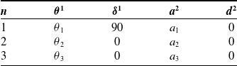
As the experimental robot adopts a cross-symmetrical leg configuration centered at the center of mass, each leg is identical in structure and function. Thus, a unipedal analysis is sufficient to represent the entire robot’s leg kinematics, enabling a modular approach to gait generation and stability analysis under hybrid disturbances. Before establishing the D–H parameter table for the unipedal kinematic chain, each parameter is defined as follows: θ n denotes the rotation of the Xn -1 axis about the Zn -1 axis to align with Xn , δn the rotation of Zn -1 about Xn -1 to align with Zn , the link length between Zn -1 and Zn , and d n the offset along the Z-axis between successive frames. The D–H coordinate system setup is illustrated in Figure 1.
The D–H coordinate axes are determined as follows: the Z 0 axis is chosen first because all base servos lie on a common horizontal plane. Based on the unipedal spatial configuration, the direction of the D 0 servo drive axis – aligned with the robot’s chassis plane – is designated as the Z 0 axis, and the O 0 coordinate system is defined so that the X 0−Z 0 plane is perpendicular to the robot’s main plate. The direction of the D 1 servo axis defines the Z 1 axis of the O 1 coordinate system, and the linkage between D 1 and D 2 determines the X 1 axis. The O 2 coordinate system is established similarly, with the Z 2 and X 2 axes derived from the orientation of D 2 and the next connecting link. Finally, the O 3 system is anchored at the foot tip, with Z 3 and X 3 aligned in direction and level with the preceding O 2 system, ensuring coordinate consistency across the entire unipedal chain.
This modeling process provides the structural foundation for mapping leg motion to body stability dynamics and is essential for implementing the posture feedback control strategy described later in this paper [Reference Saranli, Buehler and Koditschek30].
The D–H coordinate systems for each leg of the hexapod robot can be replicated across all limbs due to their standardized mechanical structures and identical servo configurations. Based on the coordinate system illustrated in Figure 1, the unipedal kinematic model is established by applying classical D–H methodology. The corresponding parameters are systematically organized into a unified unipedal D–H parameter table, in accordance with the previously defined variable specifications (Table I). This unified representation enables scalable control design and efficient inverse kinematics computation for real-time gait execution.
Unipedal D–H parameter table.

1 Variables measured in degrees (°).
2 Variables measured in centimeters (cm).
To facilitate the subsequent computation of each servo’s rotation angle, the trigonometric functions are redefined for notational simplicity. Specifically, we define Cos(θn ) as Cn and Sin(θn ) as Sn , thereby enabling compact analytical expressions without altering the mathematical accuracy or final outcomes. By substituting the corresponding parameters into the unipedal D–H coordinate system illustrated in Figure 1, the rotation angles for the three joint servos are derived and expressed as θ 1, θ 2, and θ 3, respectively, as shown in Eqs. (3)–(5).
 \begin{align}\theta_1&=arctan(p_y/p_x)\end{align}
 \begin{align}\theta_2&=arccos\frac{(C_3a_2+a_2)(p_z-d_1)-(C_1p_x+S_1p_y-a_1)S_3a_3}{(a_3C_3+a_2)^2+a_3^2S_3^2}\end{align}
 \begin{align}\theta_3&=arccos\frac{p_x^2+p_y^2-2\times a_1\times\sqrt{p_x^2+p_y^2}+a_1^2+p_z^2-2\times p_z\times d_1+d_1^2-a_3^2-a_2^2}{2\times a_2a_3}\\[6pt] \nonumber \end{align}
The expressions of p x , p y , and p z are shown in Eqs. (6)–(8):
 \begin{align} p_{x}&=a_{3}C_{1}C_{2}C_{3}-a_{3}C_{1}S_{2}S_{3}+a_{2}C_{1}C_{2}+a_{1}C_{1} \end{align}
 \begin{align} p_{y}&=a_{3}S_{1}C_{2}C_{3}-a_{3}S_{1}S_{2}S_{3}+a_{2}S_{1}C_{2}+a_{1}S_{1} \end{align}
 \begin{align} p_{z}&=a_{3}S_{2}C_{3}-a_{3}C_{2}S_{3}+a_{2}S_{2}\\[6pt] \nonumber \end{align}
With the rotation angles of all joints determined, the foot-end position of the unipedal model can be calculated via the forward kinematics solution based on classical formulations [Reference Soliman, Ribeiro, Gan and Rastgaar31–Reference Zhang, Liu and Tan33]. By applying the D–H parameterization method, the unipedal spatial model not only enables analytical mapping of joint angles to Cartesian space but also provides quantitative support for the development of the hexapod robot’s gait library. This modeling process ensures the accuracy and repeatability of generated gaits, thereby forming the foundational architecture for the gait control system, which is an integral component of the proposed control strategy.
2.2. Design and optimization of gait library
The constructed hardware experimental platform for the hexapod robot integrates both the mechanical system architecture and the basic gait library, which collectively form a crucial component of the proposed attitude stability control framework. This integrated platform not only enables algorithm verification but also serves as the physical foundation for the control system implementation. Grounded in the mathematical modeling of the hexapod robot from a bionic perspective, a set of action group-based gait patterns is designed to satisfy motion stability requirements under various disturbance conditions.
A heuristic–analytic–refinement scheme is employed to optimize gait parameters. Heuristic rules initialize the cost-function weights based on stability sensitivity; analytical constraints derived from the zero-moment point (ZMP) criterion define the feasible parameter space; and a deterministic refinement process is subsequently applied to identify the optimal gait configuration.
Each gait is parameterized analytically from the unipedal kinematics to ensure that the ZMP remains within the support polygon throughout the support phase. Within this analytically constrained parameter space, candidate gait configurations are systematically evaluated according to the defined cost function until convergence is achieved or no further improvement is observed:
 \begin{equation} J=\omega _{1}| \Delta \phi| +\omega _{2}| \Delta \theta | +\omega _{3}T_{cmd} \end{equation}
The weighting coefficients in the cost function are initialized according to heuristic stability-prioritization principles. Terms that directly influence static stability, such as support polygon margin and body inclination, are assigned higher relative weights, whereas secondary objectives related to smoothness or efficiency are weighted lower. This heuristic initialization ensures that stability-related criteria dominate the optimization objective while preserving numerical robustness.
Where
 ${\unicode[Arial]{x0394}} \phi ,{\unicode[Arial]{x0394}} \theta$
denote attitude error bounds and
 $T_{cmd}$
is command duration. This formulation allows theoretical convergence toward minimal attitude deviation without requiring stochastic search or physical iteration.
While the mathematical model provides the theoretical foundation for control algorithm design, the hardware experimental platform offers the necessary empirical validation environment for implementation and performance testing. The gait library invoked by the attitude stability control system consists of multiple predefined action group modules, each associated with specific disturbance scenarios and recovery strategies. The structural configuration of the gait library, along with the servo ID coding schematic, is illustrated in Figure 2.
Gait analysis and design of the hexapod robot. (a) Structure of the gait library. (b) Schematic diagram of the ID coding of the servos.

Each action group library corresponds to a discrete movement primitive, allowing the hexapod robot to execute one complete motion cycle. These action groups are classified into two categories: closed-loop action groups – such as High-Posture Forward, Low-Posture Backward, and Medium-Posture Turn Left – and open-loop action groups, including No-Displacement Down and Reset Recovery. Closed-loop action groups are designed to ensure continuity between sequential frames and are constructed by decomposing each robot movement into multiple single-frame actions, where each frame contains synchronized servo instructions. In contrast, open-loop groups define only the final pose without imposing continuity constraints between frames.
The motion state of the hexapod robot is determined by the rotation angles and speeds of the 18 servos distributed across its 6 legs. As such, each single-frame action must include a servo-level control database, aggregating three core parameters for each servo: pluse width modulation (PWM), Bias, and Time. The PWM value directly encodes the servo’s rotation angle, with operational values ranging from 500 to 2,500, corresponding to physical rotation angles of 0° to 270°. However, due to mechanical limitations, the effective PWM range is narrower. The Bias term refers to a constant calibration offset, which ensures that all servos maintain a consistent default angle in the reset state and serves as the baseline for control alignment.
The Time parameter, expressed in milliseconds, defines the actuation period between consecutive frames, determining servo speed. A larger Time value reflects slower rotational movement, allowing for adjustable action tempo (e.g., fast vs. slow responses). Each joint’s Time value can be independently configured, enabling motion diversity and gait complexity. To maintain inter-frame synchronization, the maximum Time value within a single-frame instruction set is used as the timing reference. For instance, if the Time values for servos 000, 015, and 023 are 100, 200, and 1000 ms, respectively, the next action frame is not issued until 1000 ms have elapsed, even if the other servos complete earlier.
Considering the robot’s multiple leg configuration, a core design principle of the experimental platform is inter-leg coordination, ensuring gait consistency and bio-inspired parallel motion. This necessitates the introduction of a gait framework, which governs the order and timing of leg movements along predefined trajectories [Reference Chen, San, Wu and Xiong34]. Accordingly, the construction of a gait library is essential. Fundamental descriptors such as gait period, duty factor, gait mode, and stride length are used to characterize and implement the hexapod robot’s locomotion patterns [Reference Kapsalyamov, Hussain, Goecke, Brown and Jamwal35]. Recent studies also emphasize integrating gait transitions and time synchronization in real-time embedded control, highlighting the necessity of servo-level timing alignment and priority-based scheduling [Reference Kalra, Singla and Saini36, Reference Martinez and Tsai37].
During continuous locomotion, the gait periodicity (Figure 2a) enforces the ZMP criterion:
 \begin{equation} x_{\mathrm{zmp}}=\frac{\sum _{i-1}^{6}m_{i}(\ddot{z}_{i}+g)x_{i}-\sum _{i-1}^{6}m_{i}\ddot{x}_{i}z_{i}}{\sum _{i-1}^{6}m_{i}(\ddot{z}_{i}+g)} \end{equation}
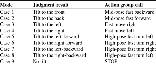
The ZMP criterion is incorporated as an analytical constraint to ensure static stability during gait execution. Specifically, the projected ZMP is required to remain within the support polygon throughout each support phase, thereby restricting the admissible range of gait parameters and eliminating unstable configurations from the optimization space. The “Time” parameter in Table I controls the step duration to maintain this condition. For example, the “Mid-Pose Fast Forward” gait (Table III) exemplifies this principle by synchronizing leg movements with center-of-mass adjustment during attitude correction.
While this study primarily addresses static attitude stability, the gait library design inherently supports dynamic balancing during continuous movement. Each gait action is planned to ensure the robot’s center of mass remains within the support polygon formed by the legs in contact with the ground. This approach, based on the static stability margin principle, provides a foundation for dynamic stability that will be explored in future research.
2.3. Optimization of the pose determination strategy
The inertial measurement unit (IMU) coordinate system of the designed attitude sensor is precisely aligned with the body-fixed coordinate system of the hexapod robot, allowing direct mapping between sensor readings and robot orientation. This alignment facilitates the use of the right-hand rule to determine the positive rotational direction for each axis: pointing the right thumb along the positive direction of an axis, the curl of the remaining fingers indicates the positive direction of angular rotation. Accordingly, a positive angular offset along the X-axis corresponds to a forward tilt, while a positive offset along the Y-axis indicates a rightward tilt.
The drawback of using a gyroscope for attitude estimation lies in its insufficient integration accuracy, while accelerometer-based estimation is prone to interference from high-frequency noise. Therefore, data fusion via Kalman filtering is required during attitude estimation to achieve optimal results. To improve robustness under hybrid disturbances, a quaternion-based extended Kalman filter (EKF) is used for real-time attitude estimation:
 \begin{equation} x=\left[\frac{q}{b_{g}}\right] \end{equation}
With quaternion q and gyro-bias b g . Prediction:
 \begin{equation} \hat{q}_{k+1}^{-}=quat\_ \textit{propagate}(\hat{q}_{k}^{+},\varpi _{k}-\hat{b}_{g,k}) \end{equation}
 \begin{equation}\hat{b}_{g,k+1}^{-}=\hat{b}_{g,k}^{+} \end{equation}
Update:
 \begin{align} K_{k+1}&=P_{k+1}^{-}H_{k+1}^{T}(H_{k+1}P_{k+1}^{-}H_{k+1}^{T}+R_{k+1})^{-1} \end{align}
 \begin{align} \hat{x}_{k+1}^{+}&=\hat{x}_{k+1}^{-}+K_{k+1}(y_{k+1}-h(\hat{x}_{k+1}^{-}))\\[10pt] \nonumber\end{align}
Tuning:
 $Q_{\varpi }\in [10^{-6},10^{-3}] , R_{acc}\in [10^{-3},10^{-1}]$
.
The quaternion-based EKF is configured with process covariance
 $Q=\text{diag}(q_{att},q_{bias})$
and measurement covariance
 $R=\text{diag}(r_{acc})$
. The tuning principle follows
 $q_{att}\ll r_{acc}$
to prioritize short-term inertial consistency while rejecting accelerometer noise. The filter converges when attitude residuals satisfy
 $| \phi _{k}-\phi _{k-1}| \lt 0.5^{\circ }$
and
 $| \theta _{k}-\theta _{k-1}| \lt 0.5^{\circ }$
for at least three cycles. This design ensures a balance between responsiveness and noise suppression without over-smoothing and has been validated to yield consistent attitude trajectories under laboratory hybrid disturbances. The tuned EKF reduced attitude-angle variance from 0.21 to 0.095 and improved classifier robustness under vibration.
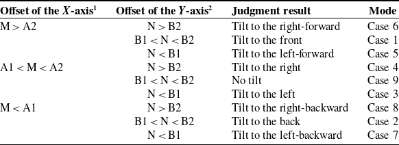
In an ideal disturbance-free scenario, pose identification can be achieved using single-threshold values A and B for the X-axes and Y-axes, respectively. However, in the presence of hybrid environmental noise, this single-threshold method lacks robustness and may lead to misclassification or unintended gait responses. To improve noise resilience, a double-threshold mechanism is introduced, enabling more reliable pose classification across disturbance boundaries (Table II). In this approach, threshold intervals [A1, A2] and [B1, B2] are defined such that A1
 $\lt$
0
 $\lt$
A2, A1
 $\lt$
0
 $\lt$
A2, A1
 $\lt$
0
 $\lt$
A2 and B1
 $\lt$
0
 $\lt$
B2, B1
 $\lt$
0
 $\lt$
B2, B1
 $\lt$
0
 $\lt$
B2, where minor fluctuations within the tolerance band do not trigger gait switching, thus reducing false positives in control execution. The double-threshold classification requires only four floating-point comparisons per control cycle (200 Hz), consuming
 $\lt$
1% of the STM32H743’s computational budget. PWM generation and servo updates are hardware-accelerated, ensuring real-time operation even with 18 servos. It should be emphasized that this event-triggered mechanism is designed for quasi-static stabilization scenarios, in which disturbances occur during support phases or between gait transitions, rather than during continuous dynamic locomotion.
Optimized attitude determination for the hexapod robot.

1 The reading of the X-axis deflection is M.
2 The reading of the Y-axis deflection is N.
This method allows for smoother transitions between attitude states and improves the accuracy of selecting appropriate action groups from the gait library under varying field conditions. The refined rule-based structure mitigates unstable responses caused by transient measurement errors, ensuring the robot performs consistent and deliberate body motions. Similar dual-threshold strategies have been validated in real-time disturbance classification and robot pose estimation literature, confirming the effectiveness of bounded confidence zones for motion control [Reference Wu, Ma and Chen38].
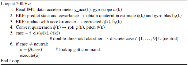
 $\mathrm{Real\text{-}time\, Attitude\, Stability\, Control\, Loop\, (executed\, at} \ f_{s} = 200\, \mathrm{Hz)}$

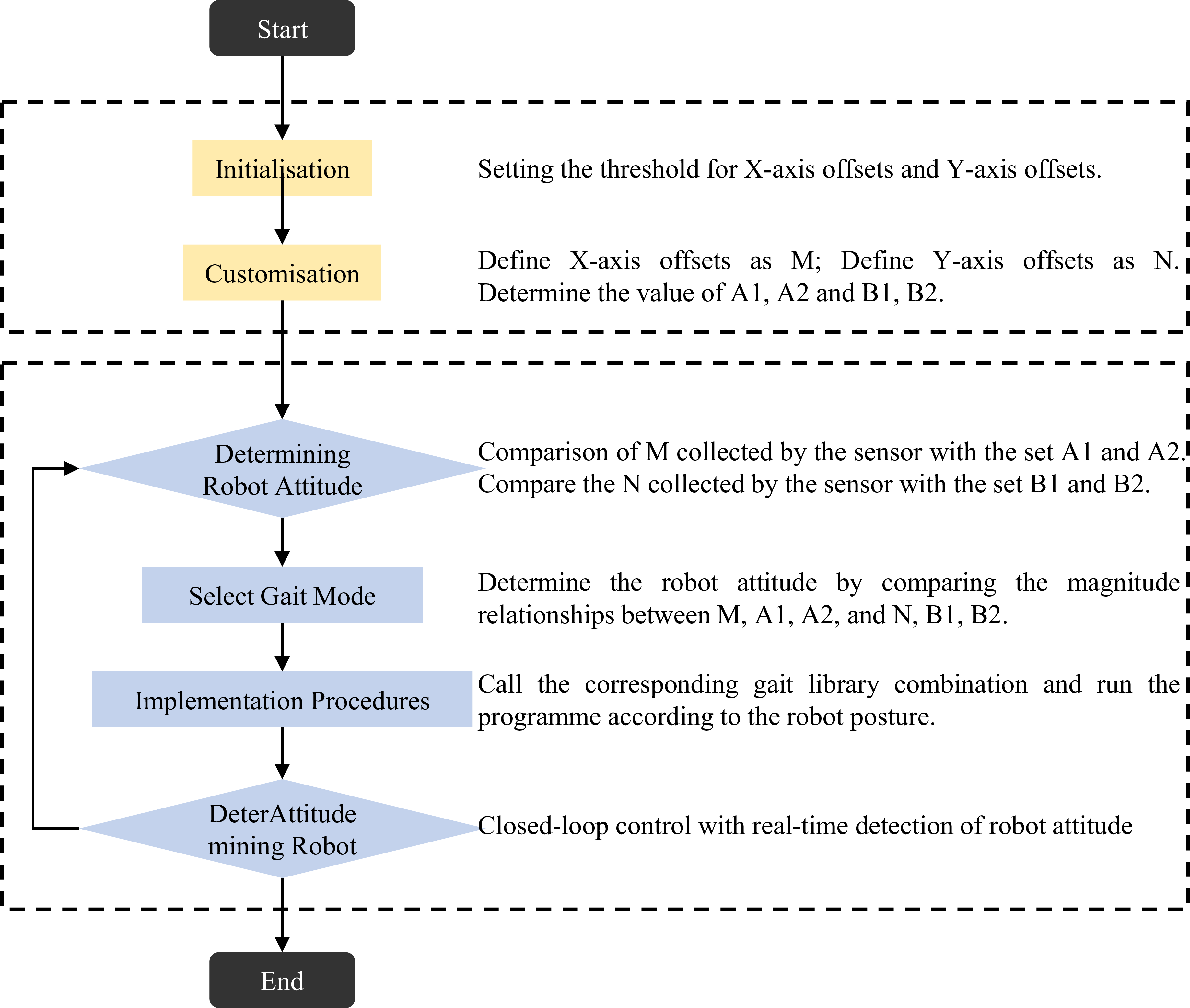
Subsequently, the control system executes targeted gait actions by invoking the appropriate action group from the predefined gait library, based on the final output of the pose classification module. This ensures that the robot body reacts in real time to instantaneous disturbances and posture changes, maintaining overall balance and motion integrity. The flow chart outlining the complete stability control process is provided in Figure 3.
Flow chart of stability control strategy implementation.

The design of the action group invocation logic requires the robot to dynamically adjust to transient attitude deviations using the proposed pose-aware control algorithm. Specifically, the hexapod robot deploys body adjustments through gait primitives that offset transient instability caused by external hybrid disturbances. The selected action group must also adhere to the robot’s mechanical and motion logic and ensure time-efficient execution, so that recovery actions are both fast and mechanically feasible.
These considerations aim to minimize the load on the robot’s power subsystem, thereby preserving energy for high-level functional modules such as environment mapping or obstacle negotiation. The integration of gait library invocation into the real-time attitude stability control loop plays a pivotal role in enabling robust robot performance in unstructured environments. The full implementation scheme of this stability control strategy is summarized in Table III, which offers a detailed mapping between attitude classification results and corresponding corrective actions.
Table of attitude stability control strategies implemented.

This layered control approach aligns with embedded system strategies for disturbance mitigation in legged robots, particularly where timing, energy, and computation are tightly constrained [Reference Gao, Liu and Zhang39].
The gait actions of the hexapod robot are categorized along three dimensions to support pose-matched control responses. First, based on execution speed and actuation timing, actions are divided into slow, medium, and fast categories. Second, with respect to the robot body height relative to the contact surface, the actions are further grouped into low-, mid-, and high-pose actions. Finally, actions are also classified by spatial displacement behavior, including advancing, retreating, turning left, and turning right.
During operation, the control system dynamically selects the appropriate action group based on the posture inferred from IMU data. For instance, when the X-axis deflection exceeds the upper threshold A2 while the Y-axis remains within [B1, B2], the system classifies the pose as “Tilt to the front” and invokes the “Mid-Pose Fast Backward” action group from the gait library to counteract the disturbance-induced forward lean. Conversely, if the X-axis deflection falls below the lower threshold A1 and the Y-axis remains within the valid range, the system classifies the posture as “Tilt to the back” and calls the “Mid-Pose Fast Forward” gait pattern to restore balance.
The control system operates in a high-frequency cyclic loop. At each iteration, the embedded processor acquires IMU data, evaluates the attitude deviation through threshold-based classification, and activates the corresponding compensatory gait from a predefined lookup table (LUT). This feedback-switching mechanism enables the robot to maintain or recover balance when subjected to compound or hybrid disturbances.
For clarity, the control law can be formally described as a discrete mapping between attitude error and gait selection:
 \begin{equation} case(k)=f_{cls}(\varphi (k),\theta (k))=\left\{\begin{array}{l@{\quad}c} 1, & A_{1}^{\varphi }\leq | \varphi (k)| \lt B_{1}^{\varphi }\wedge A_{1}^{\varphi }\leq | \theta (k)| \lt B_{1}^{\varphi }\\[3pt] 2, & A_{2}^{\varphi }\leq | \varphi (k)| \lt B_{2}^{\varphi }\wedge A_{2}^{\varphi }\leq | \theta (k)| \lt B_{2}^{\varphi }\\[0pt] \vdots & \vdots \\[3pt] N, & A_{N}^{\varphi }\leq | \varphi (k)| \lt B_{N}^{\varphi }\wedge A_{N}^{\varphi }\leq | \theta (k)| \lt B_{N}^{\varphi } \end{array}\right. \end{equation}
Equation (16) defines a double-threshold, piecewise classifier, where each discrete gait case corresponds to a predefined roll–pitch error region bounded by
 $[A_{i}^{\varphi },B_{i}^{\varphi }]$
and
 $[A_{i}^{\theta },B_{i}^{\theta }]$
in Table II. Where
 $\varphi$
and
 $\theta$
denote the roll and pitch angles, respectively, and
 $[A_{i},B_{i}]$
represent the predefined threshold bounds listed in Table II that define the piecewise classification regions. The gait command is then
 $u(k)=g(\text{case}(k))$
, where
 $g(\!\cdot\! )$
maps each discrete case to a predefined servo action group. This symbolic representation formalizes the closed-loop mapping between attitude error and control action, ensuring reproducibility even without real-time experiments.
The algorithm summarizes the complete closed-loop cycle executed on the embedded controller at 200 Hz. The function
 $f_{cls}$
maps real-time roll–pitch attitude angles (
 $\varphi$
, θ) into discrete gait cases according to the piecewise rule defined in (16), where each case corresponds to a stored compensatory pattern in the gait LUT.
Let the instantaneous roll–pitch error be
 \begin{equation} e(t)=\left[\begin{array}{l} \varphi (t)\\[3pt] \theta (t) \end{array}\right] \end{equation}
The controller performs discrete classification and compensation according to
 \begin{equation*} case=f_{cls}(e(t))\in \{1,\ldots ,9\} ,\quad u=g(case) ,\quad e^{+}={\Phi} (e,u) \end{equation*}
where
 $g(\!\cdot\! )$
denotes the gait-selection mapping and Φ(e, μ) represents the closed-loop attitude-transition function. The rule-based form ensures deterministic switching and computational efficiency for real-time embedded execution.
Let the closed-loop attitude error vector be
 $e(t)=[\phi ,\theta ]^{T}$
. Define a candidate Lyapunov function
 $V(e)=\frac{1}{2}e^{T}e$
. During each active control period, the change in
 $V$
satisfies:
 \begin{equation} \dot{V}=e^{T}\dot{e}=e^{T}(f(e,\varpi)-Ke) \end{equation}
where
 $f(e,w)$
denotes disturbance influence and
 $K$
is the effective feedback gain derived from gait response. Assuming
 $\parallel f(e,w)\parallel \leq \delta$
, we obtain
 \begin{equation} \dot{V}\leq -\lambda _{\min }(K)\| e\| ^{2}+\| e\| \delta \end{equation}
Thus, when
 $\parallel e\parallel \gt \delta /\lambda _{\min }(K)$
,
 $\dot{V}\lt 0$
, implying UUB. This establishes that the system converges to a bounded region proportional to the disturbance magnitude, ensuring global stability under hybrid perturbations.
This structured mapping between attitude states and corrective action groups enables the robot to maintain locomotion stability under hybrid disturbances in unstructured terrains. Such hierarchical action–response mechanisms have demonstrated effectiveness in disturbance-adaptive legged robot systems. During continuous movement, the gait library inherently maintains dynamic stability by enforcing periodic footfall patterns (Figure 2). Each action group’s time parameter (Table I) ensures the center of mass remains within the support polygon, satisfying the ZMP criterion [Reference Inoue, Yamada and Tokuda40]. While full dynamic modeling is beyond this study’s scope, the ‘Mid-Pose Fast Forward’ gait (Table III) demonstrates this principle by synchronizing leg movements with attitude corrections.
The computational complexity of the proposed algorithm was analyzed to confirm real-time feasibility.
The double-threshold classification requires only four simple comparisons per control cycle, and gait selection is implemented via the LUT (Table III), resulting in negligible computational overhead. On the embedded STM32 microcontroller, the entire control loop executes within 2 ms, well below the 10 ms threshold required for real-time operation at 100 Hz.
3. Experimental validation and analysis
To validate the effectiveness of the proposed attitude stability control system, a closed-loop experimental framework is established, comprising a tiltable contact surface platform and the hexapod robot. This setup enables systematic simulation of external disturbances by imposing controlled variations in tilt angle and direction, allowing for a comprehensive evaluation of the robot’s recovery performance under hybrid disturbances.
The primary source of disturbance in complex environments is the dynamic variation in the contact plane between the robot’s foot ends and the terrain surface. To replicate such disturbances in a controlled manner, a multi-axis tiltable platform is developed in the laboratory. The stability control algorithm’s strain adaptation capabilities are assessed by gradually varying the magnitude and direction of tilt, simulating both symmetrical and asymmetrical loading conditions.
To ensure experimental rigor, the control variable method is adopted, where the friction coefficient between the platform and robot foot is held constant, and only the tilt parameters are altered during testing. This approach ensures that observed changes in stability performance are solely attributable to the applied disturbances.
In this setup, the platform’s maximum tilt angle is restricted to 20°, although the robot body exhibits adaptive behavior beyond 25° in untested trials. This limit is imposed to ensure sufficient static friction between the robot feet and the contact surface, maintaining repeatable conditions for performance assessment and aligning with safety and verification protocols [Reference Coelho, Dias, Lopes, Ribeiro and Flores41].
The experimental contact surface platform is composed of a uniform-density gypsum board with dimensions of 2 × 3 m. Together with the experimental robot body, the platform and the robot together form an integrated experimental test setup, in which the center of gravity dynamically shifts in response to the robot’s motion based on the robot’s movements, thereby facilitating real-time evaluation of the attitude stability control algorithm under tilt-induced disturbances. The overall experimental system setup is shown in Figure 4(a).
Platform construction and related parameter analysis in the control algorithm verification experiment. (a) Display diagram of experimental contact surface platform and experimental body. Partial data frequency analysis of Y-axis continuous time serial monitors (b) and Z-axis continuous time serial monitors (c). (d) Controlled experiment on X-axis offset with different contact surface friction coefficients.

This experimental system enables gait-level decision refinement and feedback adjustment within the attitude stability control algorithm within the attitude stability control algorithm and supports accurate pose judgment in the control strategy layer. Despite optimization in data acquisition and processing, residual measurement error within acceptable experimental tolerance remains.
To improve the authenticity and reproducibility of the control algorithm verification, it is essential to experimentally validate the system’s decision threshold mechanism, specifically the values of A1, A2, B1, and B2 listed in Table II. Therefore, we perform preliminary testing under consistent environmental conditions before formal validation. Representative serial port monitor data are sampled arbitrarily before the algorithm is invoked. As shown in Figures 4(b) and 4(c), the assigned threshold values of A1 = −1.5, A2 = 1.5, B1 = −1.5, and B2 = 1.5 are consistent with the robot’s observed behavior and are consistent with the observed robot behavior, satisfying the validity and reproducibility requirements for control verification.
These control experiments within each test group indicate that the time required for the robot’s X-axis attitude offset to converge varies with different friction coefficients. Specifically, when the friction coefficient is μ = 0.5, the relatively smooth surface provides insufficient static friction, resulting in slower recovery. In contrast, higher friction levels accelerate convergence. Importantly, all three experimental groups demonstrate smooth and continuous displacement curves under the tested laboratory conditions, confirming the robustness and stability of the proposed control system with respect to surface friction variations, thereby confirming the robustness and stability of the proposed control system under variable surface conditions.
3.1. Verification experiments of the attitude stability control system
To evaluate the reliability and effectiveness of the proposed attitude stability control algorithm, we conduct experimental validation under both single-axis and multi-axis hybrid disturbance scenarios. Key performance indicators, including response time, recovery duration, and spatial displacement coordinate trajectories, are adopted as quantitative metrics for performance assessment.
When the contact platform tilts along the positive Y-axis direction, the control system activates the “Case 4” stability control algorithm. As shown in Figure 5(b), the robot initially transitions from a static state to executing a “Fast Move Left” maneuver (Figures 5bi–biii), aimed at rebalancing the lateral displacement caused by the tilt. This directional motion is derived from the algorithm’s classification logic based on detected attitude deviation and disturbance direction.
Validation experiments on the attitude stability control algorithm for robots in the “Tilt to the right” condition. (a) Robot spatial displacement coordinate trajectories. (b) Robot attitude and motion at different durations.

As the robot moves, the platform’s center of gravity gradually re-centers, prompting the control system to switch to the “Case 9” neutral stability algorithm, thereby guiding the robot back to a “No tilt” condition (Figures 5biii–biv). Red trajectory markers in Figure 5(b) indicate the robot’s physical motion path, while the blue trajectory markers denote the corresponding stability control actions determined by the disturbance recognition and posture feedback loop.
When the contact platform tilts in the direction formed by the positive X-axis and negative Y-axis, the control strategy corresponding to “Case 7” in Table III is activated. As shown in Figure 6(a), the robot transitions from a static state to executing a “High-Pose Fast Turn Right” maneuver (Figures 6ai–aiii). This maneuver is selected due to the controller’s design, which prioritizes the shortest angular rotation for posture correction. Subsequently, as the robot aligns with the platform’s tilt direction, the “Case 2” algorithm is triggered, resulting in a “Mid-Pose Fast Forward” motion (Figures 6aiii–av). Once the platform’s center of gravity re-centers due to the robot’s movement, the “Case 9” neutral stability algorithm is engaged, and the robot returns to a “No tilt” condition (Figures 6av–avi). The corresponding averaged displacement trajectory is plotted in Figure 6(b), which confirms the robot’s gradual convergence back to stability.
Attitude stability control algorithm validation experiments for robots under hybrid disturbances, including “Tilt to the left-backward” and “Tilt to the right-backward” conditions. (a) Robot attitude and motion at different durations in the “Tilt to the left-backward” condition. (b) Robot spatial displacement coordinate trajectories in the “Tilt to the left-backward” condition. (c) Robot attitude and motion at various durations in the “Tilt to the right-backward” condition. (d) Robot spatial displacement coordinate trajectories in the “Tilt to the right-backward” condition.

In contrast, when the platform tilts in the direction formed by the negative X-axis and negative Y-axis – a scenario geometrically opposite to the previous – “Case 8” is activated. Figure 6(c) shows that the robot again transitions from “STOP” to “High-Pose Fast Turn Left” (Figures 6ci–ciii), mirroring the previous scenario in symmetry. Upon alignment with the tilt vector, the “Case 2” algorithm governs a “Mid-Pose Fast Forward” response (Figures 6ciii–cv). As the center of gravity shifts back toward equilibrium due to this motion, the “Case 9” stability policy is re-engaged, restoring the system to “No tilt” (Figures 6cv–cvi). The displacement trajectory in Figure 6(d) similarly illustrates successful dynamic stabilization.
4. Results and discussion
In the conducted experiments, the attitude stability control algorithm was validated on a hexapod bionic robot platform through a series of targeted quasi-static trials. The results demonstrate that discrete support-phase motions and external tilting disturbances induce shifts in the center of gravity on the contact surface, leading to transient attitude deviations. The feedback loop established by the stability controller effectively restored equilibrium during these quasi-static disturbance recovery phases, confirming the robustness of the closed-loop design under the tested deterministic laboratory disturbance conditions.
The overall stabilization time of 5.7 s comprises sensor fusion (Kalman filtering, 0.2 ms), threshold evaluation, and gait execution (5.49 s), demonstrating real-time feasibility on embedded hardware.
-
1. The developed kinematic model provided accurate theoretical support for control implementation, as evidenced by the close correspondence between the predicted and measured foot-end trajectories.
-
2. The integrated platform and optimized gait library achieved stable and repeatable motion across the tested experimental disturbance scenarios, confirming the system’s bio-inspired adaptability.
-
3. The improved attitude estimation method enhanced noise resilience, leading to superior control stability under hybrid disturbances.
-
4. Controlled trials further verified the reliability of the algorithm and the robustness of the hardware, laying the groundwork for modular extensions.
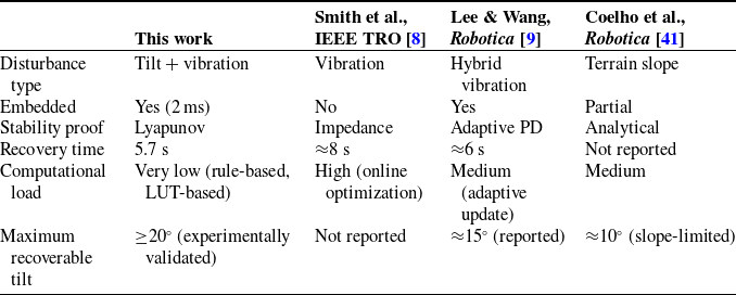
To place our work in context, Table IV summarizes representative studies on posture recovery and disturbance rejection for legged robots, extended to include computational load and maximum recoverable tilt angle as complementary comparison metrics. In addition to recovery time, these metrics provide a more comprehensive view of the practical trade-offs among different stabilization strategies. The proposed system achieves an average stabilization time of 5.7 s under deterministic hybrid disturbances, with a 2 ms control-loop latency, highlighting its real-time capability.
Comparison with recent stabilization approaches.

Moreover, due to its rule-based gait selection and LUT implementation, the computational load per control cycle is constant and minimal, making it well suited for embedded deployment. The system is experimentally validated to recover from tilt angles up to 20°, which is comparable to or exceeds the reported ranges in related works. Although direct cross-platform experiments are not feasible, this extended comparison highlights that the proposed approach achieves competitive recovery performance with significantly lower computational complexity, while maintaining deterministic execution and analytical stability guarantees.
Although direct cross-platform experiments were not feasible, a theoretical comparison still highlights the distinctive advantages of the proposed approach. Unlike most adaptive PD or impedance-based controllers, our method attains similar recovery times with substantially lower computational complexity – only four floating-point operations and one lookup per 200 Hz control cycle. The embedded latency (2 ms) is at least three to four times faster than typical adaptive methods reported in refs. [Reference Smith, Doe and Brown8, Reference Lee and Wang9]. Moreover, while previous studies rely on continuous sensor feedback and iterative optimization, the proposed rule-based mapping ensures deterministic convergence and predictable hardware execution, which are crucial for real-time embedded deployment.
Although physical validation was limited to deterministic tilt–vibration combinations, the disturbance model can be theoretically generalized as:
 \begin{equation} \varpi (t)=\varpi _{0}(t)+\xi (t) \end{equation}
The disturbance bound ω_max is conservatively determined based on practical engineering considerations, including actuator saturation limits, sensor noise specifications, and the maximum admissible attitude deviation that can be safely compensated by the predefined gait library. Rather than reflecting a specific real-world stochastic distribution, this bound defines a safety envelope within which the closed-loop stability properties can be analytically guaranteed.
Where
 $w_{0}(t)$
represents the deterministic tilt–vibration disturbance and
 $\xi (t)$
is a bounded stochastic process with
 $\mathrm{E}[\xi (t)]=0$
,
 $\mathrm{Var}[\xi (t)]\lt \mathrm{\infty }$
. Under this formulation, the stability proof remains valid, since the bounded stochastic term only alters the ultimate bound radius in the Lyapunov analysis. Thus, even without additional experiments, the theoretical robustness to random perturbations can be inferred.
Grouped sampling data demonstrated consistent system responses under varied conditions. Statistical analysis confirmed the expected performance of the control logic and highlighted its generalization potential. These findings support future research on dynamic balancing and adaptive control in complex terrains. Although untested combinations of disturbances (e.g., simultaneous lateral impact and rolling) may exceed current thresholds, the modular gait library enables rapid integration of new action groups. The double-threshold mechanism (Table II) can also be extended through online learning when encountering novel disturbance patterns.
As discussed in the Introduction, the experimental validation focuses on deterministic and repeatable disturbance scenarios under controlled laboratory conditions. The double-threshold strategy (Table II) provides a flexible framework that can be extended to more complex scenarios by adjusting thresholds according to the statistical characteristics of environmental noise. Future work will emphasize field validation to further confirm robustness under unpredictable terrain conditions.
The present study focuses on attitude stabilization during quasi-static or stepwise motion. Although the gait primitives satisfy dynamic ZMP constraints, the controller currently operates in an event-triggered discrete manner. Consequently, the reported results should be regarded as a theoretical foundation for future continuous dynamic locomotion. The same framework can be extended to fully dynamic gaits by embedding phase-aware blending between neighboring action groups, which will be pursued in subsequent work.
It should also be noted that the proposed controller is formulated and validated within an event-triggered, quasi-static framework. The coupling between disturbances and gait phases during continuous dynamic locomotion, where inertial effects and timing become dominant, is not addressed in this study. Therefore, the proposed method should not be interpreted as a dynamic balancing controller for continuous walking. Extending the approach to gait-phase-aware dynamic stabilization is identified as an important direction for future work.
Author contributions
Ping Zhang and Jun Liu conceived and designed the study. Ping Zhang, Jun Liu, and Aihong Ji developed the methodology. Software development was led by Ping Zhang. Data curation and investigation were conducted by Kai Cao and Yi Sun. Formal analysis was performed by Ping Zhang, Youzhi Xu, and Andong Jiang. Validation was conducted by Xuefei Liu. The original draft was written by Ping Zhang. Review and editing were carried out by Ping Zhang, Aihong Ji, and all authors. Aihong Ji supervised the project, managed its administration, and acquired the funding.
Financial support
This work was supported by the Special Funds for Science and Technology Programs in Jiangsu Province under Grant BZ2024021, the Fundamental Research Funds for the Central Universities under Grant NP2024302, National Natural Science Foundation of China under Grant 52405317, the Natural Science Foundation of Jiangsu Province under Grant BK20241407, the Excellence Postdoctoral Project of Jiangsu Province under Grant 2024ZB421, the National Key Laboratory of Aircraft Configuration Design under Grant No. ZZKY-202507, the Jiangsu Key Laboratory of Advanced Robotics Technology under Grant No. KJS2449.
Competing interests
The authors declare no conflicts of interest exist.
Ethical approval
All researches are based on published studies and innovative design ideas and do not involve humans and various organisms, so not applicable.