Introduction
Current wireless communication systems require compact-sized narrow-band microwave bandpass filters with low insertion loss, high return loss, sharp skirt characteristics, and extended stopband with a rejection level better than 35 dB [Reference Hong and Lancaster1]. In this context, conventional hairpin-line bandpass filters have been studied extensively by researchers to achieve the above performances [Reference Singh, Chacko, Sebastian, Thoppilan, Kotrashetti and Mande2, Reference Nwajana3]. However, the sizes of the conventional hairpin-line filters are quite large, not suitable for modern days wireless communication systems. Accordingly, a compact-sized (0.31λ g × 0.09λ g, λ g is the guided wavelength at the center frequency f 0) hairpin-line filter has been proposed by Kim et al. [Reference Kim and Kim4] by meandering two stepped-impedance resonators and placing a uniform impedance stub-load between the resonators. Alternatively, a narrowband (6.5%) stair-step hairpin-line bandpass filter of size 0.566λ g × 0.234λ g has been proposed by Mezaal et al. [Reference Mezaal and Al-Zayed5]. Later, a compact-sized (0.22λ g × 0.37λ g) bandpass filter has been designed by Qian et al. [Reference Qian and Chen6] using two proximity-coupled dual-behavior resonators. As an alternative approach, a miniaturized (0.114λ g × 0.083λ g) bandpass filter with two integrated arms split-ring resonators with a defected ground structure has been designed by Troudi et al. [Reference Troudi, Machac and Osman7]. Very recently, four sharp transmission zeros have been incorporated close to the passband edges for a compact (0.39λ g × 0.36λ g) bandpass filter to improve the skirt selectivity by Lu et al. [Reference Lu, Xu, Guo, Ren and Chen8]. However, the discussed studies in [Reference Kim and Kim4–Reference Lu, Xu, Guo, Ren and Chen8] have mainly focused on the improvements of passband response and its miniaturization. The effects of such compactness on harmonic suppression have not been investigated. Moreover, the passband bandwidths are quite large (>19%), restricting their applications for narrowband wireless systems.
Traditionally, the harmonics are generated for the coupled-line filters due to the asymmetrical even- and odd-mode phase velocities of electromagnetic (EM)-wave propagation through the dispersive microstrip-line structure. In this context, different nonuniform slow-wave coupled-line structures have been studied for the modal phase velocity compensation for parallel-coupled line bandpass filters such as wiggly lines with sinusoidal perturbations proposed in [Reference Lopetegi, Laso, Falcone, Martin, Bonache, Garcia, Perez-Cuevas, Sorolla and Guglielmi9]. As a result, multispurious harmonic suppression with a rejection level of 30 dB up to 4f 0 has been recorded. However, the design complexity of such wiggly lines has been minimized in [Reference Sánchez-Soriano, Torregrosa-Penalva and Bronchalo10] by precisely controlling the degree of coupling between the resonators. Accordingly, a rejection level of 25 dB up to 7f 0 has been achieved. However, the large sizes of the parallel-coupled line filters proposed in [Reference Lopetegi, Laso, Falcone, Martin, Bonache, Garcia, Perez-Cuevas, Sorolla and Guglielmi9, Reference Sánchez-Soriano, Torregrosa-Penalva and Bronchalo10] have restricted their applications.
Subsequently, the study of [Reference Lopetegi, Laso, Falcone, Martin, Bonache, Garcia, Perez-Cuevas, Sorolla and Guglielmi9] has been extended in [Reference Partal11] for the hairpin-line filter to reduce the size by 30% and to achieve a suppression level of 35 dB up to 2.88f 0. Later, meandered hairpin-lines have been employed by Ghalibafan et al. [Reference Ghalibafan, Fallahzadeh, Komjani and Tayarani12] and a harmonic suppression level of 35 dB up to 2f 0 has been recorded. Afterward, by utilizing the space-filling and self-similarity properties of quasi-Minkowski fractals, a rejection level of 31 dB up to 2.8f 0 has been achieved for the hairpin-line filter by Lotfi-Neyestanak et al. [Reference Lotfi-Neyestanak and Lalbakhsh13]. In this context, by applying the stagger tuning and voltage redistributions for hairpin-line filters the harmonics have been suppressed to 34 dB up to 3f 0 by Huang [Reference Huang14]. However, the sizes of the filters [Reference Partal11–Reference Huang14] are pretty large due to their conventional hairpin-line filter configuration.
Accordingly, compact-sized hairpin-line filters with harmonic suppression have been proposed by several researchers such as by Marimuthu et al. [Reference Marimuthu, Bialkowski and Abbosh15] using open-ended stepped-impedance stubs (rejection level of 15 dB up to 3.9f 0), by Huang in [Reference Huang and Shao16] combining four λ/4-folded stepped impedance resontors (SIRs) and two λ/2 SIRs (rejection level of 30 dB up to 3f 0), and by Dembele et al. [Reference Dembele, Zhang, Bao and Bukuru17] using SIR (rejection level of 18 dB up to 2.26f 0). However, rejection levels in [Reference Marimuthu, Bialkowski and Abbosh15, Reference Dembele, Zhang, Bao and Bukuru17] were not satisfactory. Subsequently, the stopband rejection level of 60 dB up to 2.04f 0 has been obtained by Cheng et al. [Reference Cheng, Lu and Huang18] using stub-loaded resonators. Later, the EM coupling has been employed in [Reference Olvera-Cervantes, Corona-Chavez, Kaur and Romero-Ramirez19] to improve the rejection bandwidth up to 3.3f 0 with a rejection level of 40 dB. Alternatively, by utilizing spectrally periodic transversal filtering sections a stopband rejection level of 30 dB up to 2.8f 0 has been obtained in [Reference Chu, Guo, Zhang and Wu20]. However, the size of the filter is quite large restricting its applications. Afterward, the study of quasi-Minkowski fractals [Reference Lotfi-Neyestanak and Lalbakhsh13] has been extended by Das et al. [Reference Das and Chatterjee21] for a double-folded hairpin-line filter and a stopband rejection level of 36 dB up to 3f 0 along with a size reduction of 30% has been reported. However, it has been revealed from [Reference Marimuthu, Bialkowski and Abbosh15–Reference Das and Chatterjee21] that there was a compromise between the stopband rejection level and stopband bandwidth. In this context, very recently, a stopband rejection level of 40 dB up to 12f 0 has been obtained in [Reference Gómez-García, Yang and Muñoz-Ferreras22] for the narrowband (3.8%) and compact (0.129λ g × 0.081λ g) bandpass filters by combining SIRs and substrate-integrated coaxial lines. However, the design complexity has been increased for [Reference Gómez-García, Yang and Muñoz-Ferreras22] due to complex perturbations proposed for harmonic suppression that also require very fine-tuning of the entire structure.
Subsequently, as an alternative approach, researchers have investigated the applications of spurlines in the microstrip filters to utilize its bandstop behavior and ability to generate multiple transmission zeros in the stopband. The size of the filters could also be reduced significantly by the slow-wave property of the spurline. In this context, different compact-sized filters with wide stopband have been proposed such as by Wang et al. [Reference Wang, Zhang, Shi, Shen, Liu and Ahn23] (size of 0.13λ g × 0.085λ g, stopband rejection level of 34 dB up to 3.6f 0), by Tang et al. [Reference Tang, Teng and Sun24] (stopband up to 8.3f 0 with a rejection level of 21 dB), by Huang et al. [Reference Huang, Shao and Chen25] (size of 0.16λ g × 0.75λ g, stopband rejection level of 20 dB up to 4f 0), and Yan et al. [Reference Yan, Huang, Huang, Ding, Wang and Bozzi26] (size of 0.44λ g × 0.29λ g, stopband rejection level of 20 dB up to 4f 0). However, the rejection levels in [Reference Tang, Teng and Sun24–Reference Yan, Huang, Huang, Ding, Wang and Bozzi26] were not satisfactory regarding modern-day applications. Thus, the design of compact, highly selective, narrowband (<5%) bandpass filters with a wide stopband beyond 4f 0 and rejection level better than 35 dB still become a challenging issue for researchers.
In the present work, the study of Das et al. [Reference Das and Chatterjee21] has been extended to design a compact and wide stopband folded hairpin-line bandpass filter (FHLBF). A significant size reduction of 24% has been achieved by reducing the cross-coupling gap between the folded lines compared to [Reference Das and Chatterjee21]. Accordingly, the coupled arms of the adjacent folded hairpin-line (FHL) cells of the folded filter have been perturbed by an L-shaped spurline to reduce the attenuation levels of the spurious harmonics beyond 35 dB. Three fourth-order folded filters have been designed with spurlines incorporated between different pairs of folded cells to validate the design scheme. All the filters have been designed on an FR4 epoxy substrate having dielectric constant ɛr = 4.4, loss tangent tan δ = 0.02, and thickness h = 1.6 mm. As a result, an upper stopband rejection level of 38 dB has been obtained up to 4.48f 0 along with a compact size of 0.62λ g × 0.12λ g.
Compact hairpin-line bandpass filter design
The proposed Chebyshev-type filter has the specifications of center frequency f 0 = 2.5 GHz, fractional bandwidth FBW = 4%, passband ripple L Ar = 0.01 dB, and stopband rejection L As = 30 dB at 2.8 GHz. Accordingly, the order N of the filter has been calculated based on the specifications as four, and the element values of the equivalent lowpass filter prototype have been determined as g 0 = 1.0000, g 1 = 0.7129, g 2 = 1.2004, g 3 = 1.3213, g 4 = 0.6476, and g 5 = 1.1008 [Reference Hong and Lancaster1]. The external quality factors of the first and fourth cells and the coupling coefficients between the adjacent hairpin-line (HL) cells placed in the hybrid coupling mode have been obtained as Q e1 = Q e4 = 17.82, M 1,2 = M 3,4 = 0.0432, M 2,3 = 0.0318 from (1) and (2) for i = 1 to N−1 [Reference Hong and Lancaster1]:


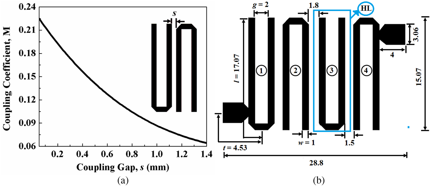
Accordingly, the coupling gaps between the adjacent cells have been determined from the design curve as plotted in Fig. 1(a) and the layout of the fourth-order hairpin-line bandpass filter with optimum dimensions has been shown in Fig. 1(b) [Reference Das and Chatterjee21].
(a) Coupling coefficient versus coupling gap plot for a pair of HL cells and (b) layout of a fourth-order conventional hairpin-line bandpass filter.

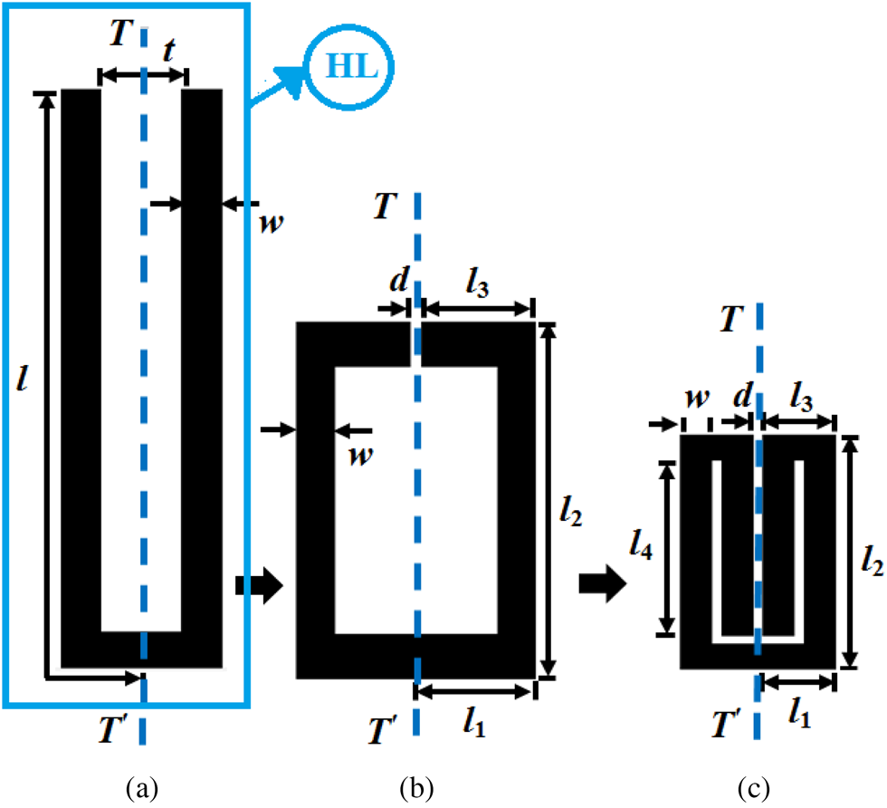
The overall size of the filter is 434 mm2 i.e. 0.42λ 0 × 0.22λ 0. The size of the conventional filter has been reduced by replacing each HL cell as shown in Fig. 1(b) with the FHL cell as shown in Fig. 2. Each FHL cell has been obtained by folding the open ends of the conventional HL cell by folding once symmetrically (about T–T′ plane) toward each other (Fig. 2(b)) and then by folding further toward the inward direction (Fig. 2(c)). The dimensions of the conventional hairpin-line cell are l = 17.07 mm, w = 1 mm, and t = 2 mm [Reference Hong and Lancaster1]. The total area occupied by the HL cell is 60.28 mm2 and accordingly, those for the FHL cell have been determined as l 1 = l 3 = 2.3 mm, l 2 = 9.11 mm, l 4 = 8.81 mm, w = 1 mm, and cross-coupling gap between the folded arms as d = 0.3 mm.
Folded mechanism of hairpin-line cell: (a) conventional HL cell, (b) first-order folding, and (c) second-order folding (FHL).

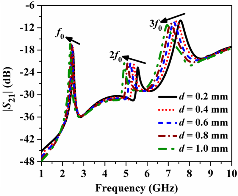
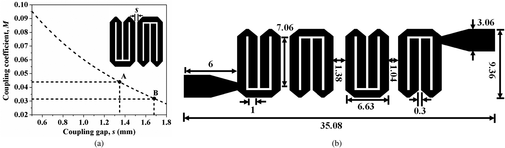
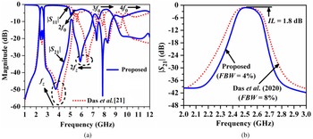
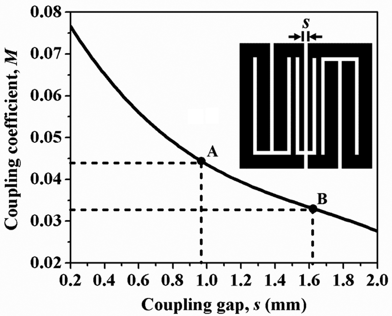
The total area occupied by the FHL cell is 44.64 mm2 and accordingly size reduction of 26% has been achieved compared to the HL cell. All the dimensions of HL and FHL cells have been tuned to f 0 = 2.5 GHz. The resonant characteristics of the unit FHL cell for different values of d have been compared in Fig. 3. The values of the second-harmonic frequency 2f 0 have been decreased with an increased attenuation level and the value of third-harmonic frequency 3f 0 has been decreased with degradation in the attenuation level. This is due to the degradation of the amount of cross-coupling between the folded arms as d increases. Accordingly, the value of d has been chosen as low as 0.3 mm by considering the fabrication tolerance. The width of the tapped-line feed-ports has been calculated as 3.06 mm for a characteristic impedance of 50 Ω. The initial values of coupling gaps between the adjacent cells have been extracted from the design curve of Fig. 4(a) as s 1,2 = s 3,4 = 1.35 mm for M 1,2 = M 3,4 = 0.0432, and s 2,3 = 1.68 mm for M 2,3 = 0.0318 (marked by A and B). Figure 4(b) shows the layout with optimized dimensions in mm. The size of the filter is 328.35 mm2 i.e. 0.51λ g × 0.14λ g and accordingly, a size reduction of 24.34% over the conventional hairpin-line filter [Reference Das and Chatterjee21] has been achieved. Figure 5(a) compares the wideband simulated S-parameter plots in the IE3D EM solver of the proposed filter with that of [Reference Das and Chatterjee21]. It has been observed that the attenuation level at the transmission zero (marked by f z) has been increased by 7 dB in the proposed filter due to the additional cross-coupling of the field lines for a small cross-coupling gap. Moreover, the attenuation level at 2f 0 has been degraded by 5 dB and the second transmission zero (marked by 2f z) has been shifted to 6 GHz from 6.7 GHz due to the additional capacitive effects in the cross-coupling gap. The attenuation level at 3f 0 has been increased by 3.5 dB along with shifting to a higher frequency region. Figure 5(b) compares the passband response comparison of the proposed folded filter with that of [Reference Das and Chatterjee21]. It has been observed that the passband bandwidth becomes narrow than that of [Reference Das and Chatterjee21] with the insertion loss of 1.8 dB at f 0 = 2.5 GHz. Accordingly, the inclusion of spurlines at the coupled edges of the adjacent resonators of the folded filter to achieve higher-order harmonics suppression performance has been studied in the following section.
Resonant characteristics of a unit FHL cell.

Fourth-order folded hairpin-line filter, (a) coupling-coefficient variation, (b) layout.

(a) Wideband response of S-parameters, (b) passband response.

Harmonic suppression by spurlines
Resonance characteristics of a spurline
The spurline is a defected structure, which is realized by etching one L-shape slot in the microstrip line [Reference Wang, Zhang, Shi, Shen, Liu and Ahn23–Reference Nguyen, Hsieh and Ball28]. It consists of a pair of coupled microstrip lines joined together at one end with the other end of one of the lines being left open as shown in Fig. 6(a). It exhibits virtually nondispersive behavior, characterized by the electromagnetic fields of the odd-mode of propagation. The conventional spurline has been characterized by the length of the open-end line l sp, open-end discontinuity gap g, width w, line width w 1, resonator length l as highlighted by the indications a, b, and c in Fig. 6(a). The center frequency f 0 of the stopband of the spurline bandstop filter is determined by l sp. However, the skirt selectivity and bandwidth are determined by g. The physical length of the spurline has been approximated by Bates [Reference Bates27] as (3):


L-shaped spurline, (a) microstrip layout diagram, (b) transmission line structure.

In (3), c is the speed of light, ɛ effo is the effective dielectric constant of the odd-mode, Z oo is the characteristic impedance of the odd-mode, C sp is the total parasitic capacitance at the end of the open line at resonance due to the gap g and Δl is the effective extension of the open line caused by g. The chain matrix of the two-port L-shaped spurline network as shown in Fig. 6(b) has been derived as [Reference Nguyen, Hsieh and Ball28]
 $$\eqalign{& \left[{\matrix{ {V_A} \cr {I_A} \cr } } \right] = \left[{\matrix{ {\cos \theta_{oe}} & {\displaystyle{\,j \over 2}( {Z_{0e}\sin \theta_{oe} + Z_{oo}\tan \theta_{oo}\cos \theta_{oe}} ) } \cr {j \displaystyle{2 \over {Z_{oe}}}\sin \theta_{oe}} & {\cos \theta_{oe}-\displaystyle{{Z_{oo}} \over {Z_{oe}}}\sin \theta_{oe}\tan \theta_{oo}} \cr}} \right] \cr & \quad \times \left[{\displaystyle{{V_B} \over {I_B}}} \right]}$$
In (5), Z 0o and Z 0e are the odd- and even-mode characteristic impedances; θ oo and θ oe are the odd- and even-mode electrical lengths respectively of the coupled-line section. Here, the terminal voltage conditions are considered as V 1 = V 2 = V A, V 4 = V B and terminating current conditions are considered as I A = I 1 + I 2, I B = −I 4, and I 3 = 0. By assuming θ oo = θ oe = θ, (5) has been modified as (6):

The equivalent |S 21| has been derived by the parameters conversion [Reference Hong and Lancaster1] and expressed as


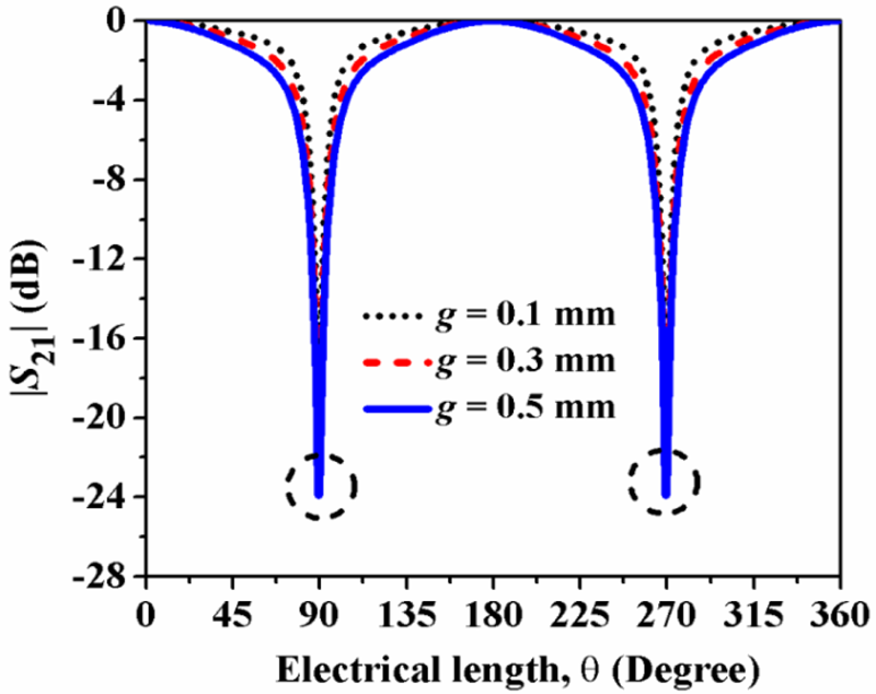
Figure 7 illustrates the |S 21| (dB) plot for the L-shaped spurline according to (7) for different values of g. The values of Z oe and Z oo in (5) have been calculated as 131.37 and 44.8 Ω for g = 0.1 mm, 135.36 and 61.87 Ω for g = 0.3 mm, and 142.1 and 77.4 Ω for g = 0.5 mm, respectively [Reference Hong and Lancaster1]. The value of the width w 1 of the resonator has been chosen as 1.0 mm (Z 0 = 84 Ω) same as that of the unit FHL cell and accordingly, the value of spurline width w has been calculated as w = (w 1 − g)/2.
Variation of |S 21| (dB) electrical length θ (degree) of the L-shaped spurline for different values of g (mm).

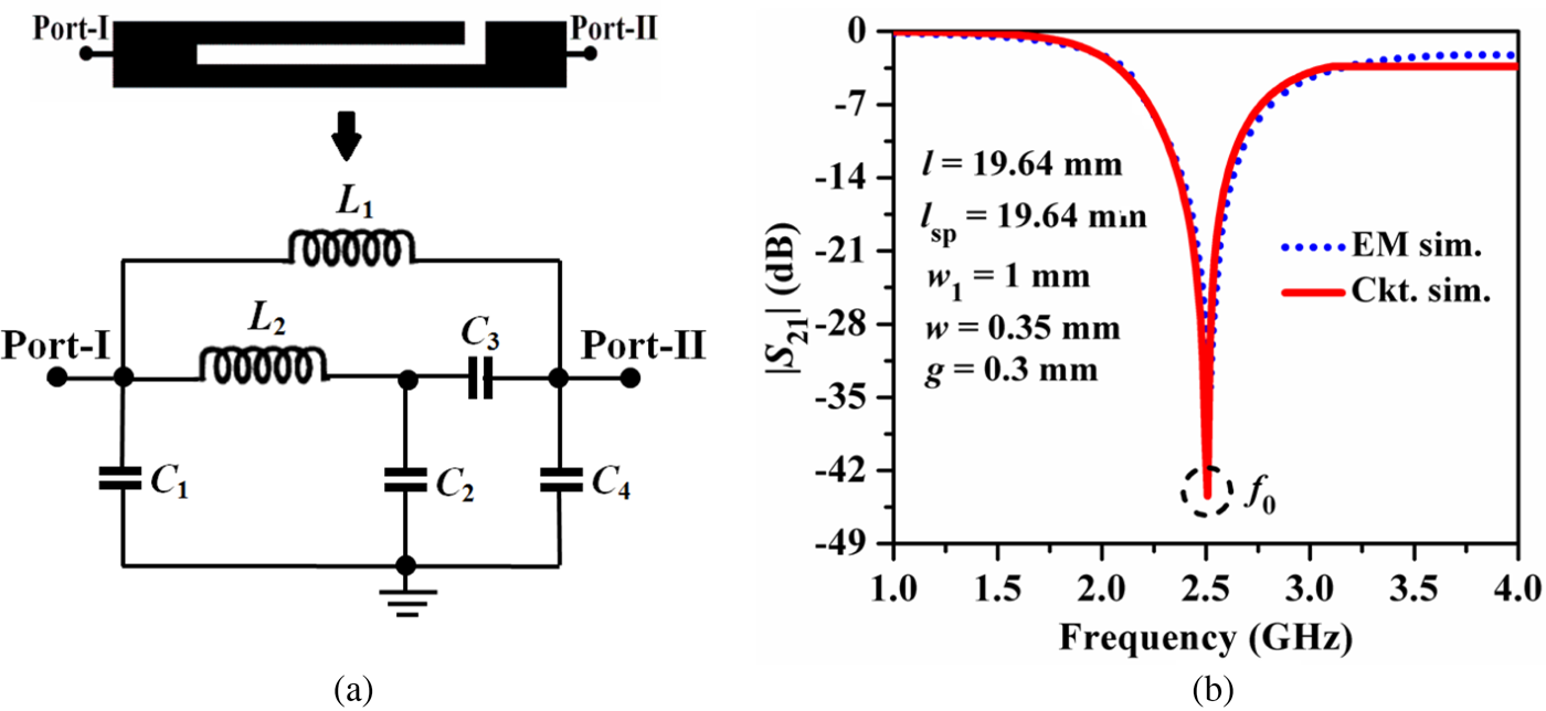
The transmission zeros of |S 21| according to (7) have been obtained by setting |S 21| = 0 under the condition of θ = (2i-1)π/2, for i = 1, 2, 3, … (2n + 1), where n is a positive integer. It has been observed that the small value of g has significantly improved the skirt selectivity of the passband and reduced the bandwidth. Thus, the values of g and θ are to be chosen adequately for desirable bandstop performance to place transmission zeros at the location of harmonics. Figure 8(a) shows the equivalent lumped elements circuit diagram of the L-shaped spurline based on the transmission line theory [Reference Hong and Lancaster1]. In this circuit, L 1 and L 2 represent the lumped inductors equivalent to the parallel-coupled lines of the spurline structure; C 1 represents the lumped capacitor equivalent to the coupling gap between the two coupled lines and the π-network consisting of C 2, C 3, and C 4 represent the open-end coupling gap of the spurline. The required values of all these elements have been obtained based on the transmission line theory [Reference Hong and Lancaster1] and tuned accordingly by performing the circuit simulation in IE3D to meet the resonant characteristics of the spurline.
(a) Equivalent lumped elements circuit diagram of the L-shaped spurline, (b) comparison of |S 21| (dB) plots between the EM simulation and the circuit simulation.

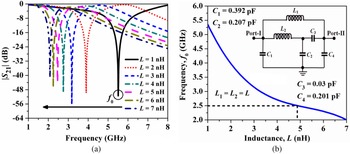
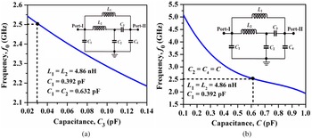
The values of the lumped elements have been calculated as L 1 = L 2 = 4.86 nH, C 1 = 0.392 pF, C 2 = 0.632 pF, C 3 = 0.03 pF, C 4 = 0.634 pF equivalent to the microstrip line dimensions: l 1 = 19.64 mm, w 1 = 1 mm, w = 0.35 mm, g = 0.3 mm and l sp = 17.64 mm for f 0 = 2.5 GHz. Figure 8(b) shows the comparison of |S 21| (dB) between the EM simulation and the circuit simulation of the spurline. It has been observed that the plots are in good agreement at the bandstop resonant frequency f 0 = 2.5 GHz. Figure 9(a) illustrates the variation of |S 21| (dB) with the incremental values of inductance L 1 = L 2 = L. The stopband resonant peak frequency f 0 has been shifted to the lower frequency regions due to the increment of the L values of the resonant circuit. Accordingly, the dependence of f 0 on L is depicted in Fig. 9(b). It has been observed that f 0 has been decreased exponentially as the value of L increases with constant values C 1, C 2, C 3, and C 4. Accordingly, the optimum value of L has been obtained as 4.86 nH.
(a) Variation of |S 21| (dB) with incremental values of L (nH), (b) variation of f 0 (GHz) with incremental values of L (nH).

Subsequently, the variation of f 0 versus the incremental values of the capacitances C 3 (pF) and C 2 = C 4 = C (pF) have been highlighted in Figs 10(a) and 10(b), respectively. It has been noticed that f 0 decreases linearly with incremental C 3 and exponentially with incremental C. This is because that as C 3 correspond to the equivalent open-end gap capacitance of the spurline and the open-end fringe fields' effects have been increased with its increment, the value of f 0 decreases. Moreover, the C 2 and C 4 are the equivalent coupling capacitances between the two resonators of the spurline slot and their values have been increased with the increase of the length of the slot. Thus, f 0 has been decreased exponentially with their incremental values. Accordingly, the optimum values of C 3 and C have been determined as 0.392 and 0.632 pF, respectively, corresponding to f 0 = 2.5 GHz. Hence, it can be concluded from the above study that the bandstop resonant frequency of the spurline can be tuned exactly at the desired frequency by adjusting the dimension of the spurline. It can be concluded from this section that the L-shaped spurline exhibits excellent bandstop resonance characteristics by introducing transmission zeros for optimum values of l sp, g, and w.
Variation of f 0 (GHz) with incremental values of (a) C 3 (pF), (b) C 2 = C 4 = C (pF).

Accordingly, this feature of L-shaped spurline has been studied further in the following section for the folded hairpin-line cells which are the building blocks of the fourth-order folded filter to achieve harmonic suppression.
Unit FHL cell with spurline
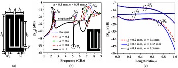
The layout of a folded hairpin-line cell with an L-shaped spurline introduced in the right-side coupling arm is shown in Fig. 11(a). In general, for a parallel-coupled line structure, the odd-mode phase velocity is more than that of even-mode and thus, spurious harmonics are generated. The primary objective to incorporate the spurline in the FHL cell is to utilize its slow-wave property for phase velocity compensation between these two modes and the ability to generate transmission zeros in the stopband due to the bandstop nature. From the literature study of spurline it has been revealed that the electromagnetic energy stored by the resonant structure has been mainly determined by the odd-mode of propagation.
Unit FHL cell with spurlines, (a) layout, (b) resonant characteristics, (c) variation of |S 21| (dB) with incremental value of α.

Thus, the spurline has been employed to the right arm of the FHL cell which is to be coupled with the left arm of the next FHL cell in the final fourth-order filter. The spur-line length ratio, α has been defined as (10)

The resonant characteristics of the unit FHL cell with spurline have been shown in Fig. 11(b). The dimensions of the FHL cell with the spurline have been chosen for the study as l 1 = 9.11 mm, l 2 = 2.3 mm, d = 0.3 mm, w 1 = 1 mm, g = 0.3 mm, w = 0.35 mm. It has been observed that the attenuation levels at 2f 0 and 3f 0 have been gradually degraded with the incremental value of α while those at f 0 have been increased due to the strong cross-coupling between the two coupled arms of the spurline. Moreover, f 0 has been shifted to lower values due to the increase in the effective electrical length of the hairpin-line due to the slow-wave structure of spurline. A sharp transmission zero marked as 2f z is observed at 5.2 GHz with the attenuation level of 59 dB for α = 1. This justifies the harmonics suppression ability of the FHL cell with the spurline. Figure 11(c) illustrates the variation of |S 21| (dB) with incremental values of α for different combinations of g and w values. It has been observed that the variation of |S 21| at f 0 is almost unaffected with α. However, the values of |S 21| at 2f 0 and 3f 0 have been decreased nonlinearly and attained a minimum value for α = 1 with g = 0.3 mm.
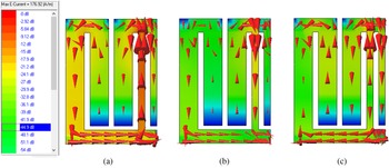
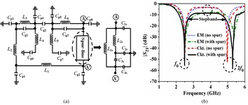
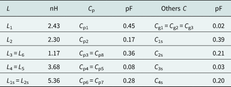
Figures 12(a)–12(c) elaborate the vector surface current density distribution for a unit FHL cell with spurline at f 0, 2f 0, and 3f 0. Maximum current density vectors have been traveled through the left arm of the spurline at f 0. However, the current distribution has been diminished at all the open ends as expected. The strength of the current density has been decreased significantly at 2f 0 and 3f 0 due to their decreased attenuation levels (Fig. 11(c)). The equivalent lumped element circuit diagram of a unit FHL cell with spurline is shown in Fig. 13(a) and the comparison of |S 21| (dB) between the EM simulation and the circuit simulation is illustrated in Fig. 13(b). Table 1 lists the values of the equivalent lumped elements tuned at f 0. It has been observed from Fig. 13(b) that there has been a close match between the EM simulation and the circuit simulation plots for both cases.
Surface current density distribution for a unit FHL cell with spurline at (a) f 0 = 2.5 GHz, (b) 2f 0 = 5.0 GHz, and (c) 3f 0 = 7.5 GHz.

Unit FHL cell with spurline, (a) equivalent lumped elements circuit diagram, (b) comparison of |S 21| (dB) variations between the EM simulation and the circuit simulation.

Values of the equivalent lumped elements of the unit FHL cell with spurline

It can be concluded from these studies that the spurline has suppressed the higher-order harmonics attenuation levels effectively for a unit FHL cell. Accordingly, the study has been extended further for a pair of FHL cells in the following section.
Pair of FHL cells with spurline
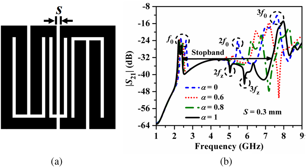
The unit FHL cells with spurlines have been cascaded symmetrically in a hybrid mode of coupling to obtain a pair of FHL cells with a coupling gap (S). Three different types of spurline configurations between the coupled arms of the FHL cells such as middle T-shaped, asymmetrical L-shaped, and the symmetrical L-shaped are highlighted in Fig. 14(a), Figs 15(a) and 16(a) respectively. The dimensions of the pair of the FHL cells are the same as those for the unit FHL cell. For the dimensions of the spurline, the value of the open-end gap and the slot gap has been chosen uniformly as 0.3 mm. Accordingly, the length of the spurline has been increased to study the effects of spurline's slow-wave nature and bandstop properties on the resonant characteristics of the FHL cells as illustrated in Figs 14(b), 15(b)–16(b) respectively. It has been observed from Fig. 14(b) that only a single transmission zero 2f z has been obtained at 4.9 GHz with the attenuation level of 37 dB for α = 1. Moreover, the attenuation level at 2f 0 has been reduced by only 4 dB compared to that without spurline, and almost unaffected at 3f 0. However, for the case of FHL cells pair with the asymmetrical L-shaped spurline (Fig. 15(b)), a wide stopband of attenuation level of 32 dB has been obtained up to 7.3 GHz for α = 1.
Pair of FHL cells with T-shaped spurline, (a) layout, (b) resonant characteristics.

Pair of FHL cells with asymmetrically placed L-shaped spur-line, (a) layout, (b) resonant characteristics.

Pair of FHL cells with symmetrically placed L-shaped spur-line, (a) layout, (b) resonant characteristics.

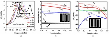
In addition, two transmission zeros 2f z at 5 GHz with an attenuation level of 43 dB and 3f z at 5.9 GHz with an attenuation level of 38 dB have been obtained. Besides, the attenuation level at 3f 0 has been degraded by 6 dB. However, the best results have obtained for the case of symmetrical L-shaped spurline as shown in Fig. 16(b). It has been noticed that the two sharp transmission zeros 2f z and 3f z have been occurred at 5 and 5.7 GHz in the stopband with the attenuation levels of 40 and 46 dB, respectively. Moreover, 3f 0 has been shifted to a higher frequency region with degradation in the attenuation level by 6 dB, justifying the ability of maximum suppression harmonics by the symmetrical L-shaped spurline compared to the other two configurations. Hence, it has been selected for the final fourth-order filter design. Figure 17(a) illustrates the effects of different length ratios on the even- and odd-mode resonant frequencies f 0e and f 0o respectively for a pair of FHL cells with symmetrical L-shaped spurline.
(a) Variation of resonant frequencies f 0e and f 0o of |S 21| (dB), (b) variation of different frequency parameters with α, (c) variation of attenuation levels with α.

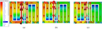
It has been observed that f 0e shifts more to lower frequency compared to f 0o. Accordingly, the difference between f 0o and f 0e reduces to 0.17 GHz for α = 1 from 0.29 GHz for a pair of FHL cells without spurline. This justifies the effectiveness of the spurline to attain the modal phase compensation for harmonic suppression. The variations of f 0e, f 0o, 2f z, 2f 0, 3f z, and 3f 0 with the incremental value of α have been illustrated in Fig. 17(b). It has been observed that the transmission zero 2f z approaches 2f 0 with the incremental values of α and finally merges at α = 0.7. This justifies the ability of modal phase velocity compensation by the spurline. A similar phenomenon has happened for 3f 0e and 3f 0o due to the dispersive nature of the spurline. Accordingly, the variations of |S 21| (dB) for different frequency parameters are highlighted in Fig. 17(c). It has been noticed that the values |S 21| have been degraded at 2f 0 and 3f 0. For more justification, the vector surface current density distribution profile for the pair of FHL cells has been demonstrated in Figs 18(a)–18(c). It has been observed that less amount of surface current density has been induced in the second FHL cell at 2f 0 and 3f 0 due to the suppression in their attenuation levels. It can be concluded from this section that the spurline with optimum dimensions can suppress the attenuation levels at higher-order harmonics.
Vector surface current density distribution for a pair of FHL cells, (a) f 0 = 2.5 GHz (b) 2f 0 = 5.0 GHz, (c) 3f 0 = 7.5 GHz.

Fourth-order filter with spurline
Three fourth-order FHLBFs have been designed by incorporating the spurlines symmetrically in different coupling regions as shown in Figs 19(a)–19(c). The optimum values of α = 0.6, g = 0.3 mm and w = 0.35 mm have been chosen for the final filters.
Layouts of fourth-order folded hairpin-line filters with spurlines between different FHL cells pair, (a) middle pair, (b) first and last pairs, (c) all pairs.

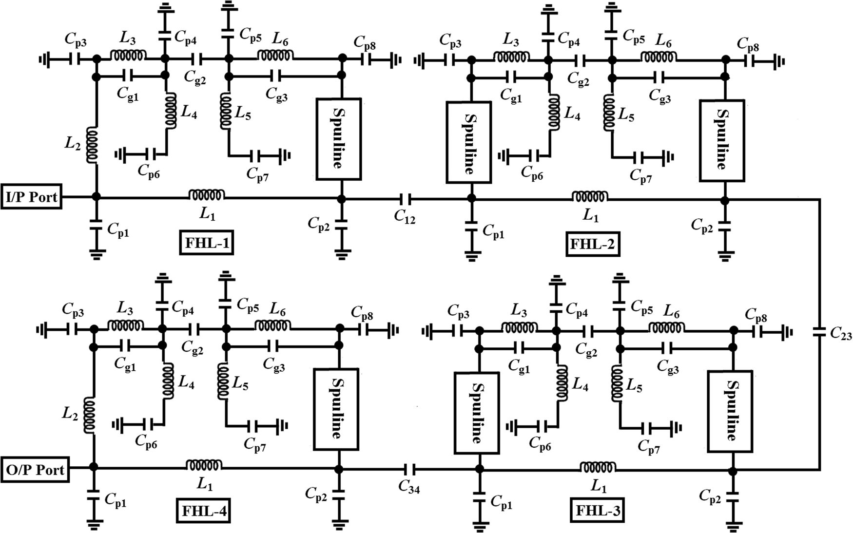
Accordingly, the initial values of the coupling gap between the adjacent FHL cells have been obtained from the design graph of the coupling coefficient (M) as shown in Fig. 20. The sizes of the designed filters are 0.59λ g × 0.13λ g, 0.59λ g × 0.13λ g, and 0.62λ g × 0.12λ g, respectively. Accordingly, size reductions of 19.1, 19.1, and 18.29% have been obtained compared to the conventional hairpin-line filter [Reference Das and Chatterjee21]. The layout diagram of the fourth-order FHLBF with spurline between all FHL cells has been depicted in Fig. 21(a), where the individual FHL cell with spurline has been marked as FHL-i, i = 1–4 and the coupling capacitances between them have been modeled by C 12, C 23, and C 34. Accordingly, the comparisons of |S 21| (dB) plots between the EM simulation and the circuit simulation has been highlighted in Fig. 21(b), whereas the equivalent lumped element circuit diagram has been depicted in Fig. 22. The dimensions of the individual FHL cell along with the spurline have been determined from the parametric study as discussed in ‘Fourth-order filter with spurline’ B-C. From Fig. 21(b) it has been observed that quite satisfactory agreement has been obtained between the simulated plots, especially in the passband.
Design curve for M versus S (mm) for a pair of FHL cells with spurline.

Fourth-order FHLBF with spurline between all FHL cells, (a) layout diagram, (b) comparison between EM simulation and circuit simulation.

Equivalent lumped elements circuit diagram for the fourth-order FHLBF with spurline placed symmetrically between all FHL cells.

Experimental results and analysis
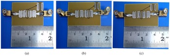
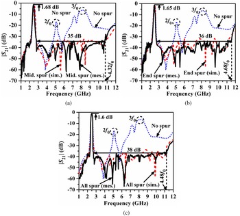
Figures 23(a)–23(c) show the fabricated prototypes of the proposed filters. The experiment has been carried out in the Agilent N9928A vector network analyzer and the measured versus simulation |S 21| (dB) plots have been highlighted in Fig. 24(a)–24(b). It has been observed that wide stopband below rejection level of 35 dB up to 10.8 GHz i.e. 4.32f 0 for the first filter, 36 dB up to 11.7 GHz i.e. 4.68f 0 for the second filter, and of 38 dB up to 11.2 GHz i.e. 4.48f 0 for the third filter have been obtained. Moreover, multiple transmission zeros with attenuation peaks of more than 55 dB have been occurred in the stopband due to the bandstop nature of the spurline, improving the filters' stopband behavior significantly.
Fabricated prototypes filters, (a) filter-I, (b) filter-II, (c) filter-III.

Comparison between simulated versus measurements results of |S 21| (dB) for folded filters, (a) Filter-I, (b) Filter-II, (c) Filter-III.

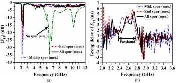
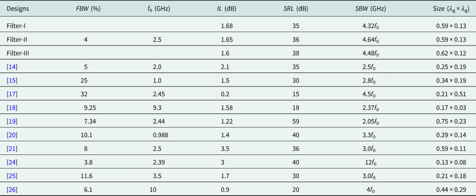
Accordingly, improvements in the harmonic rejection levels of 22, 27, and 25 dB at 2f 0 and 31, 32, and 34 dB at 3f 0 have been obtained. The insertion loss has been recorded as 1.68, 1.65, and 1.6 dB for the filters. The high value of the insertion loss has been occurred due to the lossy nature of the FR4 substrate along with some experimental tolerances incurred due to the coaxial cable and sub-miniature version A (SMA) connectors during measurements. The measured versus simulated |S 11| (dB) plots have been highlighted in Fig. 25(a). It has been observed that for all the designed filters the input reflection coefficient in the desired passband becomes better than 15 dB. Figure 25(b) compares the group delay (ns) plots of |S 21| for all the fabricated filters and satisfactory symmetrical responses have been observed in the desired passbands of the filters. Table 2 highlights the comparative study with FBW = 3 dB fractional bandwidth (%), IL = insertion loss in the passband, RC = reflection coefficient in the passband, SRL = stopband rejection level (dB), SBW = stopband rejection bandwidth, and size in terms of λ g × λ g (λ g is the guided wavelength at the center frequency f 0). It has been observed that significant improvements in the stopband rejection level have been obtained for the proposed filters than [Reference Huang14, Reference Marimuthu, Bialkowski and Abbosh15, Reference Dembele, Zhang, Bao and Bukuru17, Reference Cheng, Lu and Huang18, Reference Huang, Shao and Chen25, Reference Yan, Huang, Huang, Ding, Wang and Bozzi26]. Besides, the stopband rejection bandwidth has been improved than [Reference Huang14, Reference Marimuthu, Bialkowski and Abbosh15, Reference Cheng, Lu and Huang18–Reference Das and Chatterjee21, Reference Huang, Shao and Chen25, Reference Yan, Huang, Huang, Ding, Wang and Bozzi26]. However, the sizes of the proposed filters are less than those of [Reference Dembele, Zhang, Bao and Bukuru17, Reference Olvera-Cervantes, Corona-Chavez, Kaur and Romero-Ramirez19, Reference Yan, Huang, Huang, Ding, Wang and Bozzi26] in terms of λ g2.
Comparison between simulated versus measurements results for three fabricated filters, (a) |S 11| (dB), (b) group delay of S 21 (ns).

Comparative study with similar works

Conclusion
The present article describes the design of a compact hairpin-line filter with improved harmonics suppression performance by an L-shaped spurline. At first, the size of the conventional hairpin-line filter has been reduced to 24% by folding symmetrically the open-end arms twice toward the inward direction. All bent edges of the folded lines have been tapered to reduce the radiation loss due to the sharp edges and also smoothing the signal flow. Accordingly, the skirt characteristics of the passband have been improved due to the generation of a deep transmission zero of attenuation level of 50 dB between f 0 and 2f 0. However, the folding mechanism has little effect on the harmonics' attenuation levels. Accordingly, the L-shaped spurline has been employed symmetrically to the coupled edges of the adjacent folded cells to achieve the modal phase velocity compensation due to the bandstop and slow-wave nature of the spurline. As a result, multiple transmission zeros with attenuation levels better than 55 dB have been generated in the stopband. The length and the gap of the spurline are the critical parameters for the bandstop effects and thus, their values have been tuned optimally to achieve the maximum harmonic suppression. The insertion losses for all the filters have been recorded nearly to 1.6 dB. An extended stopband below the rejection level of 38 dB up to 4.48f 0 has been obtained experimentally with a size reduction of 18% over the conventional hairpin-line filter due to the slow-wave property of the spurline.
 Tarun Kumar Das was born in Kolkata, India, in 1979. He obtained his M.Tech. degree from WBUT, Kolkata, India, in 2008. Currently, he is working toward his Ph.D. degree at Jadavpur University and serving as an assistant professor in ECE department at FIEM, Kolkata, India. His research area includes harmonic suppression in microwave filters.
 Sayan Chatterjee was born in Kolkata, India, in 1980. He obtained his Ph.D. degree in 2015 from Jadavpur University. Currently, he is serving as an associate professor in ETCE department at JU, Kolkata, India. His research interest includes microwave and millimeter wave antennas, SIW technology, and electromagnetic interference.