INTRODUCTION
The use of heavy ion particle beams to compress fusion fuel targets in inertial confinement fusion energy schemes has long been an active area of research. More recently, there has been interest in using accelerator facilities that are used to study heavy ion fusion to carry out experiments that will advance the understanding of the physics of matter in the high-energy-density and warm dense matter regimes. Intense, space-charge-dominated beams are required, and these beams must be focused to small spots in order to either strike a fusion fuel target or heat a target so that it becomes warm dense matter. To achieve the smallest possible target spot size, the space charge of the ion beam must be neutralized.
The neutralized drift compression experiments NDCX-I and NDCX-II at Lawrence Berkeley National Laboratory use longitudinally and transversely compressed positive ion bunches to heat targets in order to perform high-energy-density physics and ion-driven inertial fusion energy experiments (Friedman et al., Reference Friedman, Barnard, Briggs, Davidson, Dorf, Grote, Henestroza, Lee, Leitner, Logan, Sefkow, Sharp, Waldron, Welch and Yu2009; Roy et al., Reference Roy, Seidl, Anders, Bieniosek, Coleman, Gilson, Greenway, Grote, Jung, Leitner, Lidia, Logan, Sefkow, Waldron and Welch2009; Seidl et al., Reference Seidl, Anders, Bieniosek, Barnard, Calanog, Chen, Cohen, Coleman, Dorf, Gilson, Grote, Jung, Leitner, Lidia, Logan, Ni, Roy, Van Den Bogert, Waldron and Welch2009). To compress the ion bunch to a small-radius, short-duration pulse, the self-electric field of the ion bunch must be neutralized to prevent the self-electric field from stopping the compression, and causing the ion bunch to expand. A source of neutralizing electrons localized near the beginning of the drift compression region does not provide adequate charge neutralization since the electrons pulled into the ion bunch compress together with the ion bunch, and are therefore heated, increasing their Debye shielding length and reducing the degree of neutralization. It is better to provide a source of neutralizing electrons throughout the drift compression region (Kaganovich et al., Reference Kaganovich, Davidson, Dorf, Startsev, Sefkow, Friedman and Lee2010). Therefore, plasma sources have been developed for both NDCX-I and NDCX-II to fill the drift compression region with dense plasma that acts as the source of neutralizing electrons.
There are several requirements that the plasma sources must meet. The plasma sources should create plasma with density greater than the beam density locally. Although relaxing this requirement can be envisioned, since nearby electrons that are not immediately in the path of the ion bunch may be pulled into the bunch if there is no strong magnetic field present that the electrons must cross, the design goal has been to have the plasma density exceed the beam density. The plasma sources should generate reasonably uniform density plasma and should not adversely affect the ion bunch propagation by introducing strong electric or magnetic fields. The plasma sources should not introduce so much neutral gas into the system that the ion bunch suffers from scattering, stripping, or charge exchange events. Finally, these sources should have long lifetimes and the ability to operate at rates up to several Hz. These requirements rule out many plasma source technologies such as simple radio-frequency-driven gas sources, electron cyclotron resonance plasma sources, or helicons. The drift compression region ranges in length from 1 to 2 m, depending on the experiment configuration, and the nominal beam pipe diameter is 7.6 cm until the final 30 cm. A 10-cm-long, 8 T solenoid magnet, used for final transverse focusing, is wound on a 3.8 cm-diameter pipe and the midplane of the solenoid is 18 cm upstream of the compressing ion bunch focal spot. The last 10 cm of drift compression takes place in a large diagnostic chamber. Three separate plasma sources are used to fill the three distinct regions with plasma: a ferroelectric plasma source in the upstream portion of the drift region; a compact plasma source in the bore of the 8 T solenoid; and a cathodic-arc plasma source in the target chamber. The cathodic-arc plasma source used in the target chamber has been discussed previously (Roy et al., Reference Roy, Seidl, Anders, Bieniosek, Coleman, Gilson, Greenway, Grote, Jung, Leitner, Lidia, Logan, Sefkow, Waldron and Welch2009) and will not be discussed here.
This paper is organized as follows. First, the ferroelectric plasma source will be discussed, including modifications to improve performance. Data will be presented that demonstrate the ability of the plasma to provide electrons to successfully neutralize the beam. Second, a compact ferroelectric plasma source for filling the volume of the 8 T solenoid will be described and measurements of the plasma properties will be presented. Finally, a flashboard plasma source will be presented.
FERROELECTRIC PLASMA SOURCE
A ferroelectric plasma source (FEPS) is used to create plasma in the upstream portion of the drift region (Efthimion et al., Reference Efthimion, Gilson, Grisham, Davidson, Logan, Seidl and Waldron2009). Ferroelectric ceramics such as lead zirconium titanate (PZT) and barium titanate (BaTi03) have relative dielectric coefficients of several thousand and large polarization surface charge densities can be created when pulsed voltages are applied across pieces of these ceramics (Rosenman et al., Reference Rosenman, Shur, Krasik and Dunaevsky2000; Dunaevsky et al., Reference Dunaevsky, Krasik, Felsteiner and Sternlieb2001). If the electrode on one face of the ceramic is not solid, but rather a mesh or grid, the large non-compensated polarization surface charge density can create a strong tangential electric field at the vacuum-ceramic-electrode interface. This strong tangential electric field leads to electron avalanching along the surface of the ferroelectric and the formation of a non-complete surface discharge, i.e., plasma that then spreads across the surface of the ceramic. The plasma density, temperature, and expansion velocity can be controlled by the parameters of the high-voltage pulse. For instance, it is observed that if the applied voltage changes rapidly in time, the plasma discharge is enhanced.
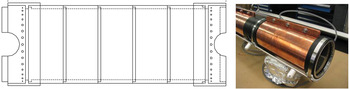
Barium titanate cylinders with an inner diameter of 7.6 cm and an outer diameter of 8.4 cm that are 4.1 cm long are stacked together to make a ferroelectric plasma source of a certain length. Barium titanate is preferred to PZT since the PZT, while having a larger relative dielectric coefficient, suffered from pitting after several hundred pulses due to the large piezoelectric effect. The large erosion rate of the PZT sample caused the plasma source to have a shorter lifetime than the barium titanate based source. The barium titanate cylinders have 3.2 mm-long steps ground on their edges so that they can be stacked together to build longer cylinders. The maximum number or cylinders stacked together in one plasma source module is typically five, both for ease of assembly and also so that these 20-cm-long modules can be added or removed from the beamline as the length of the drift compression region is increased or decreased (Fig. 1 left).
(Color online) (Left) A cross section drawing of a five-cylinder ferroelectric plasma source. The five cylinders are stacked together and Delrin collars are placed on the ends. Aluminum rings are inserted into the Delrin collars and steel wires are laced between the aluminum rings to hold the assembly together and provide electrical continuity between the perforated sheet inserts in each cylinder. (Right) The plasma source is wrapped in a copper jacket and the high-voltage lead is attached to a copper bar.

The outer surface of the barium titanate cylinders is coated with a thin silver film to form the outer electrode where the high voltage pulse is applied. The inner surface of each 4.1 cm long cylinder is fitted with a 2.5 cm-wide rolled strip of perforated steel sheet to form the inner electrode. The interface between adjacent cylinders is protected from high voltage flashover by a layer of low-out-gassing vacuum grease. The stack of cylinders is held together by placing two Delrin collars on the ends of the stack and lacing steel wire back and forth between two aluminum rings placed into the Delrin collars. The steel wire serves the additional function of electrically connecting the perforated steel sheet inserts to each other; the aluminum rings, in turn, are connected to ground. A thin copper sheet is wrapped around the outside surface of the stack of cylinders to ensure that the high voltage is applied uniformly to the outer surface (Fig. 1 right).
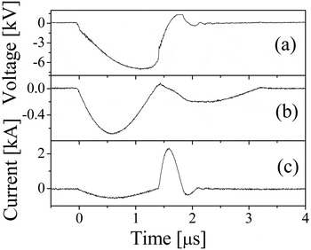
The ferroelectric plasma sources are driven by thyratron-switched 0.1 µF capacitors that are charged to approximately 9 kV. The rise-time of the voltage pulse is 200 ns and the resulting current pulse of the discharging capacitors has an amplitude of nearly 500 A and a duration of 1 µs. Typical waveforms of the voltage and current when the FEPS was operated in vacuum are shown in Figure 2, when the time delay of the crow-bar switching was τ = 1.3 µs.
Typical waveforms of the voltage and current in the case of the FEPS operation in vacuum. (a) FEPS voltage; (b) FEPS charging current; (c) FEPS short-circuit current. Storage capacitance of 70 nF, charging voltage of 11 kV.

The time required to recharge the capacitors limits the ferroelectric plasma source to a repetition rate of 0.33 Hz. Observations of the time-integrated emitted light show that the plasma is fairly uniform. Moreover, simulations have demonstrated that non-uniformities in plasma emission from the wall do not lead to significant spatial non-uniformities near the beam axis at the center of the cylinders (Sefkow et al., Reference Sefkow, Davidson and Gilson2008). The on-axis plasma density, measured by a moveable Langmuir probe, is in the mid-1010 cm−3 range (Efthimion et al., Reference Efthimion, Gilson, Grisham, Davidson, Logan, Seidl and Waldron2009). This density exceeds the NDCX-I beam density where the ferroelectric plasma source is used. The plasma persists for 15 µs before dissipating, and this is greater than the 1 µs ion bunch transit time through the drift compression region. During testing and during operation on NDCX-I, the ferroelectric plasma source has been fired over 104 times. For NDCX-II, larger beam densities are expected and so the ferroelectric plasma source will be modified to increase the plasma density it generates.
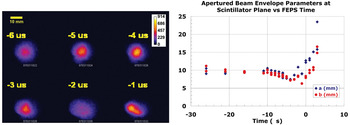
Data from experiments performed on NDCX-I clearly demonstrate the importance of beam neutralization for achieving a focused ion beam. In this particular experiment, the plasma source trigger timing was varied relative to the beam trigger signal (Coleman, Reference Coleman2008). The scintillator images of the compressed beam in Figure 3a show that if the plasma source is triggered too early (e.g., 6 µs before the beam trigger signal), the plasma will have already begun to dissipate. The plasma density will be too low, the beam neutralization will be incomplete, and the resulting size of the beam is large and the intensity of the beam is low. The timing is optimized when the plasma source is triggered 4 µs before the beam trigger signal and the beam image is compact and bright. The data in Figure 3b show the horizontal size and vertical size of the beam spot image measured from data such as those in Figure 3a. If the plasma source is triggered too late, after the master beam trigger signal and after the beam has passed through the neutralization region, the ion beam expands greatly before reaching the target because there is no plasma present to provide neutralizing electrons. These data show both that the optimal plasma source trigger timing is 4 µs before the beam trigger signal and that some plasma afterglow persists for tens of microseconds that can provide partial beam neutralization.
(Color online) (a) Scintillator images of compressing ion beams measured at the target plane for various trigger delays of the ferroelectric plasma source relative to the beam trigger signal. (b) The horizontal and vertical size of the beam spot images measured from scintillator image data. Plasma is required for effective neutralization and some plasma afterglow persists for tens of microseconds.

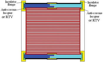
Modifications in the assembly of the stack of ceramic cylinders, the inner electrode structure (Fig. 4), and the pulser electronics will improve the ferroelectric plasma source performance, increasing the generated plasma density into the 1012 cm−3 range, which is required for NDCX-II. A silicone compound will replace the low-out-gassing vacuum grease in order to more reliably fill the void space between cylinders. Narrow, thin Kapton strips will be placed on inner surface and the outer surface to cover the gap where adjacent cylinders meet. Covering the Kapton strips with the inner and outer electrodes creates another capacitance that is in series with the capacitor formed by the ceramic material itself. The series capacitance can be significant since, even though the relative dielectric coefficient of the Kapton is small, the separation between the plates of this capacitor is small too. The addition of the series capacitance means that less surface charge will be present on the ceramic cylinder at the location of the gap between adjacent cylinders. This will reduce the chance of a flashover or breakdown between adjacent cylinders. Applying inner electrodes made from 2-mm-wide copper foil strips with conductive adhesive will ensure more uniform plasma generation since the rolled perforated steel sheet inserts used presently do not press against the inner surface of the cylinder uniformly.
(Color online) Improvements in the Ferroelectric plasma source design will enable plasmas with densities in the 1012 cm−3 range to be created. Using 2-mm-wide copper strip inner electrodes, a silicone compound (RTV), and Kapton strips to cover the joint where ceramic rings meet will raise the threshold for high-voltage breakdown and allow for an increase in the amount of plasma generated.

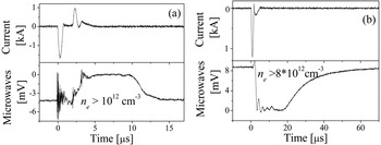
Finally, a crowbar switch will be employed to rapidly (≤ 20 ns) short circuit the high-voltage across the ceramic cylinder and create an intense burst of plasma generation. Characterization of this modified plasma source with a microwave cut-off technique showed that it operates reliably and is able to produce plasma with density up to 1012 cm−3 in a 1 cm diameter region near the center of the drift tube. Typical waveforms of the microwave envelope signal for different microwave frequencies and charging voltages of the storage capacitor are shown in Figure 5. One can see that the duration of the plasma with a density >1012 cm−3 can be as long as almost 15 µs. Also, the rise in the plasma density depends on the time delay of the crowbar switch operation. The shorter the time delay τ, the faster is the buildup of the dense plasma.
(a) Typical waveforms of the FEPS short-circuit current and microwave envelope signal at frequency of 9 GHz, storage capacitor charging voltage of 9 kV and (b) FEPS charging current and microwave envelope signal at frequency of 25 GHz. Storage capacitance of 70 nF, storage capacitor charging voltage of 11 kV.

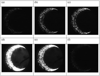
Photography of the light emission from the inner surface of the modified FEPS was carried out using a fast framing intensified camera (4Quik05E) with frame duration of 100 ns and different time delays with respect to the beginning of the driving pulse. Narrow band (10 nm) interference filters for Hα and Hβ spectral lines were also used. Typical images of the light emission from the FEPS inner surface for different time delays τd with respect to the beginning of the driving pulse are shown in Figure 6. One can see that the crowbar switch operation leads to a drastic increase in the light emission from the FEPS surface in Figure 6d. The increase in light emission indicates the generation of denser plasma with increased plasma electron temperature. Note that, due to a lower image intensifier gain, the images shown in Figures 6d–6f are actually 3.5 times brighter than they appear.
Typical images of the light emission from FEPS surface at different time delays τd with respect to the beginning of the driving pulse: (a) τd = 250 ns, (b) τd = 450 ns, (c) τd = 800 ns, (d) τd = 1100 ns – crowbar switch closed, (e) τd = 1300 ns, (f) τd = 1500 ns. MCP voltage: (a, b) 750 V, (c) 700 V, (d-f) 650 V. Frame duration of 100 ns; charging voltage of 7.8 kV, storage capacitance of 70 nF, P = 2 × 10⁻⁵ Torr.

COMPACT PLASMA SOURCE
The final focusing 8 T solenoid that is located approximately 20 cm from the focal plane of the compressing ion bunch is fabricated on a 3.8 cm-inner-diameter pipe (Roy et al., Reference Roy, Seidl, Anders, Bieniosek, Coleman, Gilson, Greenway, Grote, Jung, Leitner, Lidia, Logan, Sefkow, Waldron and Welch2009). Using a smaller diameter bore for the magnet makes the design more practical. However, the use of a strong magnetic field and smaller diameter bore make it difficult to fill the entire volume of the drift compression region with plasma. The plasma generated by the ferroelectric plasma source moves radially inward from the walls of the plasma source and does not enter the bore of the solenoid. The present NDCX-I system makes use of the cathodic-arc plasma sources that are placed in the target chamber to try and fill the solenoid with plasma. These cathodic-arc plasma sources are pointed slightly in the upstream direction so that the plasma they create is partially directed into the bore of the solenoid. Since the plasma follows the magnetic field lines, to a reasonable approximation, the plasma that reaches the midplane of the solenoid is found at radii less than 5 mm. Measurements confirm that the plasma density is low at large radius at the midplane of the solenoid (Roy et al., Reference Roy, Seidl, Anders, Bieniosek, Coleman, Gilson, Greenway, Grote, Jung, Leitner, Lidia, Logan, Sefkow, Waldron and Welch2009). The effect of magnetic mirroring also reduces the amount of plasma that can travel into the bore of the solenoid from the cathodic-arc plasma sources. Compact plasma sources have been developed that can be placed inside the bore of the magnet and generate plasma near the wall. Plasma generated near the wall inside the solenoid will follow magnetic field lines that pass through the midplane of the solenoid at large radius. A compact cathodic-arc source has been developed that generates plasma around the circumference of a ring (Anders et al., Reference Anders, Kauffeldt, Roy and Oks2011), whereas here a compact ferroelectric plasma source is discussed.
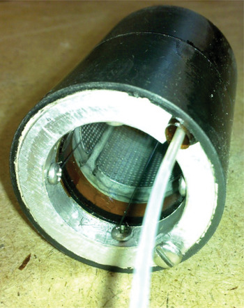
A compact barium titanate cylinder that is 3.8 cm long and 3.5 cm in diameter is the key component of the compact ferroelectric plasma source (Fig. 7). The design is otherwise similar to that of the larger-diameter ferroelectric plasma source, except that the high-voltage lead must be well insulated and pass close to both the grounded vacuum chamber wall and the side face of the ceramic cylinder. The Delrin collars are designed to completely encase the plasma source to prevent high-voltage breakdown between the outer surface of the ceramic cylinder and the grounded vacuum chamber wall. The aluminum end rings and the perforated steel sheet insert must be slotted to eliminate closed azimuthal paths for eddy currents to flow. Otherwise, the axial force on the compact plasma source generated by the pulsed magnet in the fringe-field region of the solenoid is sufficiently strong to displace the plasma source, even when radial set-screws are used to brace the plasma source against the vacuum chamber wall.
(Color online) The compact ferroelectric plasma source is only 3.8 cm in diameter in order to fit inside the bore of the 8 T solenoid. The high-voltage lead must be well-insulated and it connects to the metalized outer surface of the ceramic cylinder through a hole in the aluminum ring.

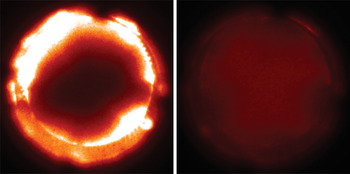
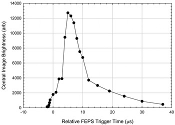
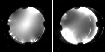
Fast images and Langmuir probe measurements were used to characterize the compact ferroelectric plasma source before it was tested in the strong magnetic field. Camera images with a 1 µs exposure time show that the plasma is formed at the wall and fills the volume with uniform plasma in 5 µs (Fig. 8). The data in Figure 9 show the brightness at the centers of a series of such camera images in order to observe the time evolution of the plasma. The image brightness, and hence the plasma density, has a pronounced maximum that is several microseconds in duration. This is followed by the afterglow, which lasts for tens of microseconds. This demonstrates that dense plasma can be made whose lifetime is comparable to the transit time of the ion beam through the plasma. When the charging voltage is 8 kV and the peak current through the source is 200 A, Langmuir probe measurements performed at the center of the plasma source show that the density is in the mid-1011 cm−3 range. Long-exposure camera images of the plasma taken when the compact ferroelectric plasma source was tested in the bore of a 3 T solenoidal magnetic field show that the magnetic field lines keep the plasma near the wall of the plasma source. Without the applied magnetic field, the plasma density is larger in the center (Fig. 10).
(Color online) Intensified CCD camera images with a 1 µs exposure time show that after 3 µs (left) the plasma density is concentrated near the wall of the cylinder, but that after 5 µs (right) the plasma has filled the volume uniformly. Each image is an average of 8 shots of the plasma source.

The central brightness of fast camera images of the compact ferroelectric plasma source show that a dense plasma fills the device in several microseconds. The afterglow lasts for tens of microseconds.

Long-exposure camera images capture 8 consecutive shots of the compact ferroelectric plasma source when it is placed in the fringe field region of the bore of a 3 T pulsed solenoid. (Left) Without a magnetic field, the plasma converges at the center of the plasma source. (Right) The plasma source is triggered when a 3 T magnetic field is present, and the plasma cannot move as easily towards the axis.

FLASHBOARD PLASMA SOURCE
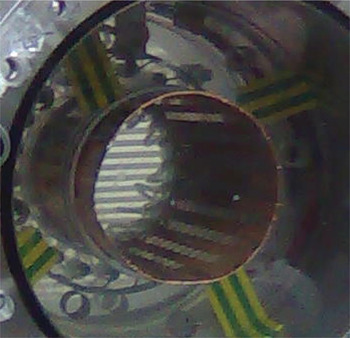
A possible alternative to the ferroelectric ceramic, that can generate large plasma density, is a flashboard-based plasma source. A 0.2-mm -thick, flexible sheet of printed circuit board material is coated with copper on the back side and multiple parallel chains of copper pads are created on the front surface using photolithography, as shown in Figure 11.
(Color online) The cylindrical flashboard plasma source demonstrates that the circuit board material is easily rolled into a 7.6 cm-diameter cylinder. The chains of copper pads are visible running axially along the inner surface of the rolled cylinder.

A high-voltage pulse applied across the two ends of the chains causes plasma formation between the copper pads in a chain. The end opposite from where the high voltage is applied is connected to the back side electrode so that the current flowing along the surface from pad to pad returns along the back surface.
The copper pads are nearly elliptical and are 10 mm long and 5 mm across. The spacing between pads in a chain is 1 mm and the spacing between chains is 5 mm. The spacing between chains must be large enough to prevent breakdowns from occurring between chains. The circuit board material is flexible and can easily be rolled into 7.6 cm-diameter cylinders as is required for the upstream portion of the drift compression region. This flashboard operates as a common strip line where the magnetic field of the current is in the volume between the front and rear electrode. Thus, the plasma formed, as the result of the surface breakdown, is pushed by the magnetic pressure outwards from the flashboard surface and towards the axis of the cylinder.
The charging voltage of the 0.1 µF capacitor in the plasma source pulser is 16 kV and is larger than the charging voltage for the ferroelectric plasma source. The peak current is 4 kA for the flashboard plasma source used in these experiments. The ability to drive the plasma source with larger voltages and achieve greater maximum currents without a breakdown of the material allows the flashboard plasma source to reach plasmas densities in the 1013 cm−3 range. This density was measured using collimated Faraday cups, and by making microwave cut-off measurements with 9 GHz and 25 GHz generators. These plasma sources have been tested for over 6000 shots with good reproducibility and without significant deterioration of the plasma parameters.
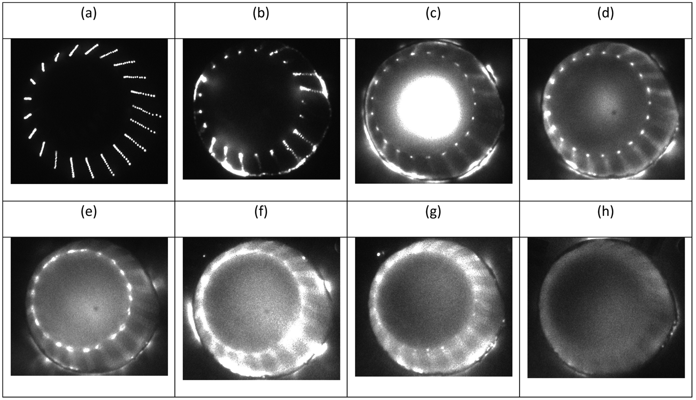
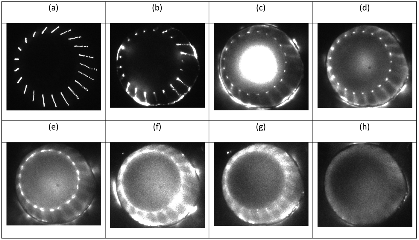
Typical framing images (frame duration of 10 ns) obtained during flashboard operation in air and in vacuum are shown in Fig. 12. One can see that in air all the discharge chains are working with the same brightness of emitted light.
Typical framing images of the flashboard spark gaps light emission. (a) air; (b-h) vacuum, P = 5 × 10⁻⁵ Torr, frame duration of 10 ns; (a) time delay τ = 0.6 µs, (b) τ = 0.4 µs, (c) τ = 1.3 µs, (d) τ = 1.8 µs, (e) τ = 2.8 µs, (f) τ = 3.3 µs, (g) τ = 3.8 µs, (h) τ = 4.3 µs, (i) τ = 5.3 µs, (a-e) MCP voltage 700 V, (f-h) MCP voltage 750 V, Id ≈ 5.1 kA.
CONCLUSION
Compressed ion beams are candidates for inertial confinement fusion energy drivers and are useful for the creation of matter in the high-energy-density regime. The NDCX-I and NDCX-II, and their successors, require a source of electrons to neutralize the strong self-fields of a compressing positive ion bunch. Plasma sources that make plasmas with densities greater than the local beam density are good sources of these electrons. Cathodic-arc plasma sources are used in the target chamber to fill the region immediately upstream of the target location with plasma and to direct plasma upstream into the bore of the 8 T solenoid that is used for focusing the ion bunch. Ferroelectric plasma sources are used in the upstream portion of the drift compression region since they provide sufficient plasma density and the modular design of the plasma source allows the plasma source length to be changed as the length of the drift compression region changes. Compact plasma sources have been developed that will be placed in the bore of the 8 T solenoid to generate plasma near the wall that will flow along magnetic field lines and provide plasma in the magnet mid-plane at large radius. Optimizing the present plasma sources and the development of alternative plasma source technologies will allow plasmas with larger densities to be created and deployed in future beam compression experiments that will require these larger plasma densities.
ACKNOWLEDGEMENTS
This research was supported by the U.S. Department of Energy and by the BSF grant No. 2006373.