Introduction
Medulloblastoma and primitive neuroectodermal tumours are common paediatric tumours. The present standard of care for these tumours includes surgery followed by craniospinal irradiation (CSI) with chemotherapy or hormonal therapy.Reference Gottardo and Gajjar 1 – Reference Freeman, Taylor, Kortmann and Carrie 4 Current treatment protocols using a combination of combination of surgery, chemotherapy and external beam radiation produce a 5-year overall survival in excess of 65% in medulloblastoma.Reference del Charco, Bolek and McCollough 5 Traditional radiotherapy delivery techniques were conventional simulator-based two-dimensional techniques. However, more modern techniques include CT simulator-based three-dimensional conformal radiotherapy (3DCRT), intensity-modulated radiotherapy (IMRT) or rotational therapy-based techniques like volumetric-modulated arc therapy (VMAT) and tomotherapy.Reference del Charco, Bolek and McCollough 5 – Reference Sharma, Gupta, Jalali, Master, Phurailatpam and Sarin 14 The anticipated gains with modern radiotherapy techniques include better conformity and a decreased rate of radiotherapy-related side effects such as neuro-cognitive defects, hypothyroidism, cardiac toxicity, pneumonitis, fertility issues, bone growth-related abnormalities and secondary cancers.Reference Bloom 15 – Reference Deutsch, Thomas and Krischer 17 Further modifications of such modern techniques have enabled supine craniospinal radiotherapy and junction shift free radiotherapy.Reference Fogliata, Bergström and Cafaro 12 , Reference Lee, Brooks, Bedford, Warrington and Saran 13 , Reference Ganesh, Sarkar, Munshi and Mohanti 18
Although modern radiotherapy delivery techniques have resulted in significant improvement in the dose conformity and the reduction in the dose to organs at risk (OAR), non-target volume still receives a significant dose.Reference Munshi and Jalali 8 – Reference Sharma, Gupta, Jalali, Master, Phurailatpam and Sarin 14 Several investigators have investigated the VMAT-based CSI. In recent times, linear accelerator-based CSI delivery techniques demonstrated a significant improvement in dose homogeneity and junction-free therapy delivery using intensity-modulated techniques.Reference Fogliata, Bergström and Cafaro 12 , Reference Lee, Brooks, Bedford, Warrington and Saran 13
For arc therapy technique, scattered dose to the organs away from the neural-axis plane is significantly high as large monitor units (MUs) are delivered from the multiple gantry angles. Although several investigators have investigated the CSI using intensity-modulated technique, which is majorly concentrating of dose homogeneity and advantage of junction-free technique.Reference Fogliata, Bergström and Cafaro 12 – Reference South, Chiu, Teh, Bloch, Schroeder and Paulino 25
The present dosimetric challenge is to further reduce the dose to the non-target volume areas. Recent breakthroughs in linear accelerator technology include flattening filter-free (3F) beam, finer width multileaf collimator (MLC) (0·5 cm) and advanced delivery technique like VMAT. Primary aim of this dosimetric study was to test the efficacy of these recent improvements of linear accelerators in CSI delivery. The secondary aim was to verify the gantry rotational angle used in the VMAT plan as compared with that used by previous investigators.
Materials and methods
CT datasets of five patients of medulloblastoma were taken for this dosimetric analysis.
Patient immobilisation and simulation
Patients were placed in the CT-simulator couch in head first supine position with hand by the side. The alignment of the patient was verified in anteroposterior topograph and suitable adjustments made to make the spine straight. A four clamp thermoplastic mask was made for immobilisation of the head and upper chest. The CT scans were done on True-flight (Philips, The Netherland) (64 slice scanner) system. Helical 3 mm CT cuts were taken from the top of the cranium to the pelvic area. Images were transferred to contouring station.
Complete target volume was divided into two portions: brain planning target volume (PTV) and the spine PTV. The cranial contouring included the complete brain and C5/C6 level of spine. The cranial end of spinal contouring started from the caudal limit of cranial contouring. The caudal limit of spinal contouring was upto the end of thecal sac. PTVs for the brain and spine was generated using a 3 and 7 mm margin, respectively. A total of 22 structures including body contour, NTID (nontumor integral dose: dose to body excluding PTV), kidneys, liver, lung, heart, thyroid, bowel, left and right optic nerve, left and right eye, genitals, ovaries, left and right cochlea, pharynx, oesophagus, right and left lung, and oral cavity were contoured as OAR.
Treatment planning
Treatment planning including 3DCRT and VMAT, was done with two or three isocentres based on the PTV length for all treatment planning. Only two isocentres were used for the paediatric cases (with patient height <1·3 m and PTV length≈60 cm). For longer PTV length (PTV≥65 cm), a third isocentre was added in the inferior portion of the spine. Both PTVs were planned for a prescribed dose of 35 Gy in 21 fractions. Treatment planning was done using 6 MV X-rays.
3DCRT techniques
A 3DCRT treatment plan was generated in CMS XIO (V4.80.00.7; Elekta CMS, Syynavil, CA, USA) using Elekta Synergy (MLCi2) linear accelerator configuration (Elekta, Stockholm, Sweden). 3DCRT plans for the cranium consisted of two nearly parallel opposed portals using MLC with a 3 mm margin to PTV. One or two posterior fields were used for the spine depending on the length of spinal PTV. Appropriate collimator, couch and gantry rotations were used to achieve the exact junction matching at the cranial and spinal field junction as also the upper and lower spinal field junction. Spine fields were planned in ±90º couch angle for exact matching of the divergence with the brain fields. A nominal collimation angle (≈4º) and couch angle (≈6–8º) were used for the brain fields to match the inferior divergence of the brain fields with the superior spine field divergence. A nominal gantry angle (≈6–8º) was used in the brain portals for matching the beam divergence at the eye level. No gap was provided between the brain and spine field.Reference Munshi and Jalali 8 A typical 3DCRT plan beam arrangement showed in Figure 2 (panel 6). Dose normalisation for brain was done to a point near the centre of the brain to obtain a 95% dose coverage, and the spine PTV normalisation were chosen to cover the anterior aspect of the spine with the 95% dose.
VMAT technique
VMAT plans were created in X-ray voxel Monte Carlo-based CMS MONACO (V5.00.02; CMS Elekta) treatment planning system (TPS). Our VMAT treatment planning methodology has some similarity to the technique earlier described by Fogliata et al. and Lee et al. However, our technique had significant modifications from the techniques in literature including difference in the assigned gantry rotational angle.Reference Fogliata, Bergström and Cafaro 12 , Reference Lee, Brooks, Bedford, Warrington and Saran 13 Our planning strategy described in detail elsewhere.Reference Ganesh, Sarkar, Munshi and Mohanti 18 Brain PTV was assigned a 360° rotational beam. The spine fields were treated with an upper spine field and lower spine field (in case of two spinal isocentres). Spine PTV was facilitated with one or two isocentres depending upon its length. For upper and lower spine fields, VMAT rotational angles of 60 and 100° symmetric about 180° gantry positions were used. In a single spine isocentre approach, the assigned gantry angle was 60°. No geometrical matching using couch or collimator rotation was used. Fluence optimisations for both PTVs were done in a synchronised setting. An advanced optimiser engine TPS ruled out the requirement of an additional contour in the junction(s) to obtain the homogeneous dose distribution. Typically, MONACO TPS works in volumetric prescription and does not required any dose normalisation. Each individual PTV (brain or spine) was facilitated by dose from the direct beam; however, there was a substantial contribution from the adjacent beam(s) as well. In our technique, a low-dose gradient was created at the field junction over a long length (>10 cm) by tapering the isodoses. Low gradient junction was created at the brain–spine PTV junction for two isocentric methods, where for three isocentric technique in the brain–upper spine and upper spine–lower spine junction. Details of low-dose gradient junction technique have been described elsewhere.Reference Fogliata, Bergström and Cafaro 12 , Reference Lee, Brooks, Bedford, Warrington and Saran 13 The dose tapering was created by the optimiser engine considering the dose contribution from all the available fields depending on the largest beam dimension. At first, the clinically delivered plan was created using Synergy 6 MV flat beam. Optimisation process typically began with an initial set of arbitrarily chosen OAR constraints, which were tweaked during the optimisation to obtain the desired PTV coverage and OAR dose. All the VMAT plans in test arm were generated using the final set of constraints obtain in the control arm. It was ensured that 95% of the prescription dose was received by 95% of volume for both PTVs.
Linear accelerator and beam models
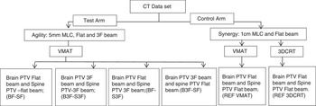
Three different beam models were used in the TPS in this study: (1) Agility flat beam, (2) Agility 3F beam and (3) Synergy flat beam. Elekta Synergy Linear Accelerator (Elekta) is equipped with the MLCi2 MLC head having 40 pairs of MLC leaves, maximum field size of 40×40 cm2 and 1 cm projection at the isocentric plane. Agility (Elekta) has 80 pairs of MLC leaves with the maximum field of 40×40 cm2 size and MLC width of 0·5 cm at the isocentric plane. Figure 1 represents the study scheme. A total of six plans were generated for each patient with different combination of beam models and MLC models. The following test arm VMAT plans were generated with the Agility MLC head: (1) brain PTV flat beam and spine PTV flat beam {BF-SF}, (2) brain PTV 3F beam and spine PTV 3F beam {B3F-S3F}, (3) brain PTV flat beam and spine PTV 3F beam {BF-S3F}, (4) brain PTV 3F beam and spine PTV flat beam (B3F-SF). With the MLCi2 (Synergy) and flatten beam (6 MV), the following two plans were generated and these were considered as the gold standards for comparison for the test arms. These were the (5) brain PTV flat beam and spine PTV flat beam (REF VMAT) and (6) 3DCRT using the flat beam (REF 3DCRT).
Schematic diagram of the appropriate technique evaluation scheme. Notes: Control arm represents a standard linear accelerator with 1 cm multileaf collimator (MLC) and flat beam; containing two techniques: three-dimensional conformal plan (3DCRT) and volumetric-modulated arc therapy (VMAT). Test arm represent a high-end linear accelerator with 5 mm MLC, flat and flattening filter-free (3F) beam. Test arm contains four VMAT plans for all combination of 3F and flat beam in two different planning target volumes (PTVs). Abbreviations: B, brain PTV; S, spine PTV; REF, reference.

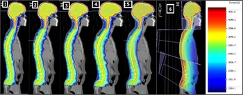
Figure 2 represents the obtained dose distribution for all the noted techniques for a prescription dose of 35 Gy.
A typical isodose distribution for volumetric-modulated arc therapy (VMAT) and three-dimensional conformal radiotherapy (3DCRT) plans. Notes: Different multileaf collimator and beam model is presented in sequence as follows: (1) BF-SF (all plane), (2) B3F-S3F, (3) BF-S3F, (4) B3F-SF, (5) REF VMAT, (6)REF 3DCRT. Abbreviations: B, brain planning target volume (PTV); S, spine PTV; 3F, flattening filter-free beam; REF, reference.

Planning comparison and statistical analysis
We report the relative merit of different MLC, beam model and planning techniques in terms of PTV coverage, OAR sparing and delivered MU. 3DCRT and VMAT treatment plans created in the Synergy were considered as the base line plan for the comparison. All results presented are in the form of mean±SD.
A total of five parameters were evaluated for spine PTV and brain PTV. These included maximum PTV dose, mean PTV dose, dose received by 95% of the PTV volume (D95%PTV, cGy), PTV volume receiving 95% of the dose (V95%PTV, %) and PTV volume receiving more than 107% of dose (V107%PTV, %).
For OAR low intermediate and high-dose levels were compared between the reference and test arm plans. Five OAR thyroid, combined lung and combined kidney was reported for dose received by 5, 50, 75 and 90% volume and mean dose along with the standard deviations.
To evaluate the variation between control arm and the test arm two sets of p values (statistical significance) for 95% confidence interval was calculated using paired sample t-test for PTV, OARs and unspecified tissues. The first and second set of p values was attributed to statistical significance between test arm VMAT plans with respect to reference arm 3DCRT and VMAT plans, respectively. Statistical significance (p value) for 3DCRT were calculated for the combinations between REF 3DCRT-BF-SF, REF 3DCRT-B3F-S3F, REF 3DCRT-BF-S3F and REF 3DCRT-B3F-SF. For VMAT plans tested combinations were REF VMAT-BF-SF, REF VMAT-B3F-S3F, REF VMAT-BF-S3F and REF VMAT-B3F-SF.
Results
PTV
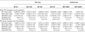
Table 1 represents the dose volume analysis for brain and spine PTV averaged over all the patients. First four columns indicate the test MLC-beam models whereas the 5th and 6th columns represent the control arm plans for VMAT and 3DCRT, respectively. The variation was observed between the reference arm (REF 3DCRT and REF VMAT) and test arm VMAT plans for all tested parameters (D95%PTV, V95%PTV, V107%PTV, PTV mean dose) for PTV brain was insignificant. Comparison of PTV brain D95% showed a difference of 51 cGy between all the control and test arm 3DCRT and VMAT plans. V95% and V107% shows a difference of 1·2% (range 98·4±1·1–97·2±2·5%) and 1·9% (range 1·1±1·7–3·0±4·2%). Statistical analysis for brain PTV reveals p value in the range 0·06–0·87 and 0·6–0·88 for reference arm 3DCRT and VMAT, respectively, when tested against test arm VMAT plans. This indicates a statistically insignificant dose variation in PTV brain between different tested technique, beam and MLC models.
Variation of planning target volume (PTV) dose between different beam model and multileaf collimator (MLC)

Notes: Control arm consists two plans, volumetric-modulated arc therapy (VMAT) and three-dimensional conformal plan (3DCRT) using Synergy flat beam. Test arm consists of four plans using Agility multileaf collimator and two different beam models flat beam and flattening filter-free (3F) beam. All data averaged over five patients. Each data entry indicate the mean±SD.
Abbreviations: B, brain PTV; S, spine PTV; REF, reference.
PTV spine shows a similar statistically insignificant variation for the evaluated parameters (D95%PTV, V95%PTV, V107%PTV, PTV mean dose) when tested between control and test arm VMAT (0·0 6≤p≤0·87) plans. However, a significant variation of the REF 3DCRT plan with the test arm VMAT plans (0·01≤p≤0·2) was observed. The variation was observed mainly for PTV spine mean dose and hot spot identifier parameters like V107%.
Body/NTID and OAR
For analysing low-dose region, dose spillage over following two objects was considered (a) body and (b) NTID. In our study, body was considered to be any non-delineated tissue (non-PTV, non-OAR) inside the external contour and NTID was the non-PTV tissue volume generated by subtracting the PTV from body volume.
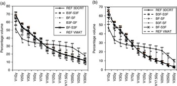
The dose spillage outside PTV was evaluated for 1, 2, 3, 5, 7, 10, 12, 15, 17·5 (50% of prescription dose), 20, 25 and 30 Gy over the body and NTID. Figure 3 presents the variation of specified dose on Body (Figure 3a) and NTID (Figure 3b) for the doses averaged over all the patients. In low-dose range of 1–3 Gy, 3F beam (B3F-S3F) showed highest dose spillage (1 Gy spillage to 692±6·8% of body and 66·2±5·9% of NTID volume for B3F-S3F beam) and Synergy flattened beam showed the least spillage (1 Gy spillage to 61·0±8·6% of body volume and 57·3±7·5% of NTID volume). As shown in Figure 3, 3DCRT technique delivered a significantly lesser dose spillage (1–7 Gy range) compared with that of any of the volumetric plans. Beyond 6·5–7 Gy all VMAT plans shows a lesser dose spillage to body and NTID than the 3DCRT plans. Difference of dose spillage between 3DCRT and VMAT plans to body/NTID increased in the range 7·5–20 Gy. Beyond 20 Gy, again the difference between 3DCRT and VMAT dose spillage start reducing. Statistical analysis revealed insignificant dose variation for body between reference 3DCRT and comparative VMAT plans only at 7 Gy. For all other spillage dose levels (1–5 and 10–30 Gy) dose variation between 3DCRT and VMAT was significant (0·0≤p≤0·05). In the VMAT plans, we could found a statistically significant difference of the spillage dose (p=0·02) at 2 Gy level between REF VMAT and B3F-SF in only one case. For the entire range of tested spillage dose levels (1 Gy and 3–30 Gy) reference arm VMAT plan was not statistically different from the test arm plans.
(a) Average dose variation in body (undelineate tissue) and (b) in NTID [total scanned volume−planning target volume (PTV)] for three-dimensional conformal plan (3DCRT) and volumetric-modulated arc therapy (VMAT) technique. Notes: This information relates to the dose spillage from PTV. The cross-over between 3DCRT and VMAT happen take place at 6·8 Gy for body (a) and 6·5 Gy for NTID. Lower doses <7 Gy is found to be increased in VMAT. Limit bar for each data point indicate the SD. Abbreviations: REF, reference; B, brain PTV; 3F, flattening filter-free beam; S, spine PTV.

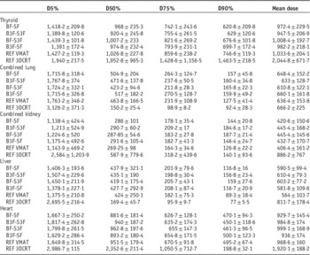
For delineated OARs mean dose values and their standard deviation for thyroid, combined lung and combined kidney are presented in Table 2. However, full table with 18 organs is available in Supplementary Table S1. For thyroid reference arm 3DCRT and test arm VMAT dose was significantly different only for mean dose and D5% (p<0·03). For rest of all parameters, D50%, D75% and D90% attributed to 3DCRT plan were statistically similar to the VMAT plans. Further, all test arm VMAT plans were not different from the reference arm VMAT plan (REF VMAT) in its all tested parameters (0·16≤p≤0·93) except a single exception at D75% dose level between REF VMAT and BF-SF (p=0·04). Reference arm 3DCRT and VAMT plan exhibit highest mean dose for thyroid compared with any test arm plans. If only VMAT plans in reference and test arm were compared mean dose difference yields a maximum dose variation of only 106·4 cGy. However, when 3DCRT plan was incorporated in the comparison, the mean dose variation was significantly high (1,097·3 cGy). For right lung, 3DCRT dose was significantly different as compared with the test arm VMAT plans only with respect to the D5% and D50% dose levels (p=0·01). For all other dose levels, these two (reference arm 3DCRT and VMAT plans) had no significant difference with the test arm VAMT plan (0·05≤p≤0·89). Left lung exhibit statistically significant dose difference between 3DCRT plan and the test arm VMAT plans for D5%, D50% and D90% dose levels (0·01≤p<0·05). Reference arm VMAT plan (REF VMAT) demonstrated significant dose variation as compared with the test arm VMAT plans only at D90% dose level (p=0·01). For rest of the dose levels (D5%, D50%, D75% and mean dose), the dose difference was not statistically significant (0·08≤p≤0·9). Both the kidneys exhibited a significant dose variation between 3DCRT and test arm VMAT plan only at D5% dose levels. At D75% and D90% dose levels reference arm VMAT plan (REF VMAT) exhibited the minimum dose among all the VMAT plans. Although the maximum dose difference (39 and 60·9 cGy) between reference and test arm VMAT plan was not significant at these two dose levels (D75% and D90%), however, a statistically significant variation was observed (0·05<p≤0·00) between them. Reference arm 3DCRT exhibit a significant dose variation with the test arm VMAT plans at all the tested dose levels (D5%, D50%, D75%, D90% and mean dose) for liver (0·00≤p<0·5) and at D5% and D50% dose level in case of heart. Mean dose and the low-dose levels like D5% attributed to 3DCRT were significantly higher than the VMAT obtained doses for both liver and heart. Out of all tested organs 3DCRT yield a lesser dose at D50%, D75%, D90% levels only in case of kidney and liver.
Variation of organs at risks doses with between the test and reference (REF) arm plans

Notes: Test arm consists of the plans from Agility multileaf collimator (MLC) head having width of 0·5 cm at isocentre, flat and flattening filter-free (3F) beam. REF arm consists of three-dimensional conformal plan (3DCRT) and volumetric-modulated arc therapy (VMAT) plan from synergy MLC (1 cm at isocentre) and flat beam. Complete list of 18 organs is available in Supplementary Material.
Abbreviations: B, brain planning target volume (PTV); S, spine PTV.
MUs
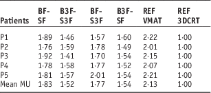
Table 3 presents the MU values for all patients normalised to 3DCRT reference arm. Highest MU for VMAT plans were shown by Synergy flat beam (REF VMAT) and average MU was 2·3 times 3DCRT MU. With the 3F beam of Agility MLC, with mean MU were 1·52 times the MU required for 3DCRT. For VMAT plans 3F beam required lesser MU to deliver same dose when compared with a flat beam. Agility flat beam (BF-SF) also did not reduce the MU significantly depicting the mean MU of 1·77 times of 3DCRT MU. B3F-SF resulted in lesser mean MU (1·54×3DCRT MU) compared with BF-S3F (1·77×3DCRT MU).
Discussion
Fogliata et al. was first to describe the CSI using VMAT. They established the advantage of multiple isocentric volumetric-modulated technique over the conventional techniques and the capability to treat the complete neural-axis without field junctions changing. Further a separate study using VMAT-based CSI reported by Lee et al.Reference Lee, Brooks, Bedford, Warrington and Saran 13 compared conventional radiotherapy techniques with an improved conformity and marginally different dose to the OAR at the cost of higher MU when compared with 3DCRT. CSI irradiation using VMAT technique described by Fogliata et al. and Lee et al. gives two distinct advantages over the conventional techniques such as 3DCRT. The first advantage is of dose uniformity and homogeneity in the neuraxis. The second, as demonstrated in our own previous study is non-requirement of a junction shift.Reference Ganesh, Sarkar, Munshi and Mohanti 18 However, VMAT delivery faces challenges as well. The primary challenge remains to reduce the intermediate and low radiation dose to the OAR. In the present study, we tested the efficacy of different beam models (flat beam and 3F) and two MLC models for reduction of the organ doses and total integral dose to the body.
In our study, parameters like mean D95% and V95% demonstrated a dose variation of <1% among the competing VMAT reference plan and test arm generated from different beam and MLC models.
If we compared all the possible plans generated by VMAT and 3DCRT in the present analysis, the maximum interplan variation for above parameters was 2·3%. The variation of the parameters attributed to PTV dose coverage like (D95% or V95%) did not exhibit any significant dose variation between all the reference and test arm plans. Further, the small standard deviation observed (not exceeding 100 cGy except mean and maximum dose for PTV spine) indicates a small inter-patient dose variation of VMAT or 3DCRT doses for spine and brain PTV. Only notable and clinically significant variation between VMAT and 3DCRT was obtained for maximum dose, mean dose and V107% for spine PTV. Higher mean dose and hot spot were attributed to single direct posterior beam used in 3DCRT. Several other investigators have described CSI techniques using IMRT.Reference Sharma, Gupta, Jalali, Master, Phurailatpam and Sarin 14 , Reference Jan, Jarmo, Paula and Heikki 19 – Reference South, Chiu, Teh, Bloch, Schroeder and Paulino 25 However, these IMRT techniques suffer from the demerits such as a 3DCRT like beam arrangement and restricted jaw movement.Reference Sharma, Gupta, Jalali, Master, Phurailatpam and Sarin 14 , Reference Jan, Jarmo, Paula and Heikki 19 – Reference South, Chiu, Teh, Bloch, Schroeder and Paulino 25 These techniques lead to compromised dose homogeneity in neuraxis as well as the requirement of junction shifts. In our study, we used a junction-free technique for VMAT planning, similar in some respects to that described by Fogliata et al.Reference Fogliata, Bergström and Cafaro 12 or Lee et al.Reference Lee, Brooks, Bedford, Warrington and Saran 13 . Lee et al.Reference Lee, Brooks, Bedford, Warrington and Saran 13 used full arc gantry rotation for all the isocentres, having total gantry rotation of 720º (two full arc) and 1,080º(three full arc) for two and three isocentric plans, respectively. In our case, the total cumulative gantry rotation over all isocentres does not exceed 520 and 420º for three and two isocentric techniques, respectively. Lee et al.Reference Lee, Brooks, Bedford, Warrington and Saran 13 observed a reduction in V10 Gy (42·7% RxD) to body/NTID in VMAT when compared with 3DCRT. Although our (35 Gy) prescription dose was 150% higher to Lee et al. (23·4 Gy), we observed a reduction of VMAT V7·5 Gy (21·4% RxD) to body/NTID when compared with 3DCRT. A significant reduction on dose spillage in our study to that of the Lee et al.Reference Lee, Brooks, Bedford, Warrington and Saran 13 was attributed to the smaller gantry rotation. When testing the different MLC and beam model, a minor difference in dose spillage in NTID/body was observed at very low-dose range (1–5 Gy). BF-S3F and REF VMAT produced highest and lowest dose spillage, respectively, for both NTID and body (unspecified tissue) in low-dose range. This indicates the increase in the spillage of dose to the body/NTID by the use of 3F beam and smaller size MLC. Mean doses to the OAR like liver, heart, thyroid, kidney, in our study did not differ significantly from literature series.Reference Fogliata, Bergström and Cafaro 12 , Reference Lee, Brooks, Bedford, Warrington and Saran 13 Our study as well as earlier studies do not show any influence of assigned gantry rotation except for body and NTID. It is likely because in inverse planning, OAR doses are more influenced by the prescribed constraints rather than assigned gantry rotation.
We observed a mixed result for OAR doses attributed to different MLC beam model and delivery technique. Reference arm 3DCRT produces statistically significant dose difference for at least 50% evaluated parameters and OAR combinations. However, reference arm VMAT plan (REF VMAT) did not differ dosimetrically from the test arm VMAT plans. This indicates that 3F beam or finer MLC have no significant advantage over flat beam and conventional MLC on CSI dosimetry based on VMAT planning.
While discussing the influence of the MLC and beam model, we observed a small standard deviation between a particular tested MLC and beam model for a particular organ. Among all the VMAT plans in our study, we did not observe a variation of OAR doses exceeding 1 Gy, except in case of maximum dose of combined kidney. A relatively higher standard deviation was obtained for inter-patient dose variation. This indicates that dose variation attributed to the patient-specific anatomy was higher compared with the dose variation attributed to the MLC-beam model. As a corollary it can be concluded that MLC and beam model have negligible influence in the CSI dosimetry using VMAT technique.
A large number of centres practice linear accelerator-based CSI delivery using 3DCRT, as VMAT delivery is limited by the availability of high-end linear accelerators and advance TPS. Therefore, we incorporated 3DCRT as one of the gold standard arms for the completeness of the study.
To our knowledge, no such study as ours has been done in the context of CSI. Recent studies for have reported the feasibility and efficacy of the 3F for sites like liver stereotactic body radiotherapy (SBRT), prostate, lung (SBRT) and oesophagus.Reference Reggiori, Mancosu and Castiglioni 26 – Reference Thomas, Popple, Prendergast, Clark, Dobelbower and Fiveash 30 In all studies, only marginal variation of target conformity homogeneity and OAR sparing was noted. Our study demonstrates that the only noticeable difference between different MLC and beam model is the reduction in treatment time (MU). Field attributed to brain PTV required more MU than the spine field as the modulation degree is higher in brain PTV. Therefore, when brain PTV was planned with 3F beam, it showed a lesser MU than when planned with flat beam. The difference of MU between Agility (5 mm MLC) and Synergy (1 cm MLC width) flat beams were probably attributed to the difference in the MLC width and MLC speed.
It may be questioned why a 3F beam was chosen for the study, especially in view of literature reports suggesting utility of 3F beams for small tumours. We had evaluated the ratio of width of the body contour to that of spine PTV. The average width of the body and the spine PTV in transverse section was found to be 26·7±8·2 cm (range 17·3–40·7 cm) and 3·9±0·7 cm (range 5·1–3·4 cm), respectively. Ratio of body with respect to spine PTV was 6·8:1. Although the spine PTV is long in the craniocaudal direction, it is relatively small in the axial plane when compared with the axial width of the body. Dose spillage in body/NTID is directly attributed to the dose gradient in the axial plane as the gantry rotation is limited to the axial plane only, therefore use of 3F beam is justified, at least theoretically, to generate high-dose gradient in the axial plane. However, we have not observed any definite advantage on the dose spillage of using the 3F beam as compared with a plane beam. This is probably attributed to high-MLC leakage in 3F beam. The justification of use for brain PTV is evident from Table 3. Use of 3F beam significantly reduces the treatment time leading to B3F-S3F having minimum MUs when compared with other VMAT plans. Further B3F-SF also shows a lesser MU than BF-S3F establishing the efficacy of 3F beam for brain PTV.
Planned monitor unit (MU) for different multileaf collimator and beam model of test and reference (REF) arm for five patients

Note: All MUs were normalised to respective three-dimensional conformal plan (3DCRT) MU of each patient.
Abbreviations: B, brain planning target volume (PTV); S, spine PTV; 3F, flattening filter-free beam; VMAT, volumetric-modulated arc therapy.
It is apparent that linear accelerator-based practice has improved PTV dose homogeneity and conformity and reduced OAR doses significantly over last decade with the transition from 3DCRT to IMRT/VMAT. However, this is often at the cost of higher delivered MU. Further, more advanced technologies such as VMAT and use of 3F beam do not provide incremental dose distribution improvement.
Conclusion
VMAT with use of shorter arc for the spine PTV reduces the delivery time as well as the low-dose area significantly. Use of full rotational arcs for spinal fields should be strongly discouraged.
Advanced MLC models with 5 mm MLC leaf width (Agility) in combination with 3F beam offer no advantage over the conventional 1 cm MLC (Synergy) using flat beam in CSI. The only likely benefit of using a 3F beam is faster treatment delivery. VMAT shows a notable advantage over conventional technique at the cost of significantly high low-dose spillage.
Acknowledgements
The authors sincerely acknowledge the suggestion from Professor B. R. K. Gupta, Head, Department of Physics, GLA University, Mathura, Uttar Pradesh and linguistic correction by Dr. Anusheel Munshi Additional director, Department of Radiation oncology, Fortis memorial research Institute, Gurgaon, Haryana, India.
Advances in knowledge: this study will further the knowledge regarding help in choosing appropriate beam, MLC model and gantry rotation angle for LINAC-based CSI technique.
Supplementary Material
To view supplementary material for this article, please visit http://dx.doi.org/doi:10.1017/S146039691600042X