1. Introduction
Robotic systems play an important role in various orbital missions [Reference Sąsiadek and Sąsiadek1]. The manipulators that are currently operating on orbit are mounted on the International Space Station (ISS) [Reference Ticker and Callen2]. The Space Station Remote Manipulator System (SSRMS) is used in the station assembly and maintenance [Reference Gibbs and Sachdev3]. It is foreseen that robotic systems will also be utilised during construction of future space stations [Reference Rembala and Ower4] and in other on-orbit assembly operations [Reference Xue, Liu, Wu and Tong5]. Manipulators will be mounted on unmanned satellites and will perform operations with high level of autonomy [Reference Belonozhko and Kravets6]. The development of technology in the next decade should enable such satellite-manipulator systems to perform On-Orbit Servicing (OOS) missions [Reference Li, Cheng, Liu, Wang, Shi, Tang, Gao, Zeng, Chai, Luo, Cong and Gao7]. OOS missions are considered to prolong the operational lifetime of satellites [Reference Hudson and Kolosa8]. Autonomous satellite-manipulator system could also be used to capture space debris and to remove them from orbit [Reference Shan, Guo and Gill9, Reference Mark and Kamath10]. Active debris removal (ADR) missions are necessary to prevent further growth of debris population in orbit around the Earth [Reference Murtaza, Pirzada, Xu and Jianwei11]. Several concepts of ADR missions were proposed in recent years (e.g., the European Space Agency’s e.Deorbit mission [Reference Estable, Pruvost, Ferreira, Telaar, Fruhnert, Imhof, Rybus, Peckover, Lucas, Ahmed, Oki, Wygachiewicz, Kicman, Lukasik, Santos, Milhano, Arroz, Biesbroek and Wolahan12]).
The capture manoeuvre performed on orbit with the use of manipulator is the most challenging element of the planned OOS and ADR missions [Reference Seweryn and Sąsiadek13]. The captured target object may be uncontrolled and tumbling. Elements of this object (e.g., solar panels and other appendages) must be treated as obstacles in the manipulator’s workspace. Moreover, during on-orbit operations, the motion of the manipulator influences the position and orientation of the servicing satellite [Reference Dubowsky and Papadopoulos14]. Thus, the dynamic coupling between the satellite and the manipulator must be taken into account by the control system [Reference Umetani and Yoshida15]. In this paper, we focus on the problem of planning a suitable trajectory of the manipulator during orbital operations. Trajectory planning can be performed before the beginning of the capture manoeuvre, while the servicing satellite is waiting in a safe point. Review of various trajectory planning methods developed for the manipulator mounted on the servicing satellite can be found in ref. [Reference Papadopoulos, Aghili, Ma and Lampariello16]. The proposed methods include, i.a., optimisation techniques [Reference Wang, Luo, Fang and Yuan17, Reference Jin, Rocco and Geng18]. The approach proposed in ref. [Reference Zhang, Jia, Chen and Sun19] allows to minimise disturbances of the satellite orientation caused by the contact between the manipulator tip and the target object. Methods that allow to reduce joint velocities, accelerations and control torques are particularly interesting in both terrestrial [Reference Trigatti, Boscariol, Scalera, Pillan, Gasparetto, Gasparetto and Ceccarelli20] and space applications [Reference Rybus, Seweryn and Sąsiadek21]. The trajectory selected for the capture manoeuvre must ensure that the manipulator avoids collisions with obstacles. The collision-free trajectory planning methods developed for fixed-base manipulators working on Earth [Reference Masehian and Sedighizadeh22, Reference Gasparetto, Boscariol, Lanzutti and Vidoni23] cannot be directly applied for the manipulator mounted on the satellite. Several different approaches were proposed for planning collision-free manipulator trajectories during operations performed on orbit [Reference Rybus24]: methods based on the artificial potential field (APF) [Reference Yanoshita and Tsuda25], non-linear optimisation techniques [Reference Lampariello26], methods based on the A* algorithm [Reference Gao, Jia, Sun and Chen27] and methods based on the rapidly exploring random trees (RRT) algorithm [Reference Benevides, Grassi, Osório and Gonçalves28].
The RRT algorithm is searching for a suitable trajectory by randomly building a trajectory tree that fills the configuration space of the considered system [Reference LaValle and Kuffner29]. Such approach for trajectory planning is commonly used for fixed-base manipulators working on Earth [Reference Zhang, Wang, Zheng and Yu30–Reference Han and Liu32]. Application of the RRT algorithm for the specific case of the manipulator mounted on the satellite was firstly presented by Benevides and Grassi [Reference Benevides and Grassi33] and by Rybus and Seweryn [Reference Rybus and Seweryn34]. An approach based on the RRT algorithm and Forward and Backward Reaching Inverse Kinematics (FABRIK) algorithm was proposed in ref. [Reference Xie, Zhang, Wu, Shi, Chen, Wu and Mantey35]. This method was demonstrated in simulations performed for a 7-Degree-of-Freedom (DoF) spatial manipulator. Combination of RRT and shape control method was proposed in ref. [Reference Zhang, Liu and Li36] for hyper-redundant space manipulator. Changes of the servicing satellite orientation caused by the motion of the manipulator during the capture manoeuvre may disturb communication link or power generation. Thus, trajectory planning methods that allow minimisation of orientation changes are particularly interesting [Reference Zong, Emami and Luo37]. A trajectory planning method based on the RRT algorithm that allows to restrict satellite orientation disturbances was proposed in ref. [Reference Zhang and Zhu38]. This approach does not require the solution of the inverse kinematics problem. Applications of more advanced variants of the RRT algorithm (e.g., bidirectional RRT) were also proposed. In ref. [Reference Rybus39], the bidirectional rapidly exploring random trees (BiRRT) algorithm was applied for a non-redundant planar manipulator mounted on the satellite to plan a collision-free trajectory that allows to obtain the desired position of the manipulator tip and the desired orientation of the satellite. Trajectory planning based on the RRT algorithm was also proposed for systems composed of two manipulators mounted on a single servicing satellite [Reference Serrantola, Bueno and Grassi40, Reference Serrantola and Grassi41]. As explained in ref. [Reference Basmadji, Seweryn and Sasiadek42], in some cases, application of a multi-arm space robot is more efficient than application of a robot equipped with one manipulator. In case of a dual-arm space robot, the RRT algorithm can also be applied for planning trajectory that ensures no changes of the servicing satellite orientation [Reference Bhargava, Mithun, Anurag, Hafez and Shah43–Reference Pareekutty, James, Ravindran and Shah45].
Other applications of the RRT algorithm in space robotics include a method for choosing the caging configuration of the hyper-redundant manipulator used to wrap its whole body around the captured object [Reference Wan, Sun and Yuan46]. The RRT algorithm is also proposed for planning the trajectory of the servicing satellite during close-proximity operations [Reference Doerr and Linares47]. Such application of the RRT algorithm was validated in experiments [Reference Zappulla, Virgili-Llop and Romano48, Reference Basmadji, Chmaj, Rybus and Seweryn49].
In this paper, we consider a servicing satellite equipped with a single manipulator. We propose application of a bidirectional RRT algorithm for collision-free trajectory planning of the manipulator during pre-capture operations. The proposed method has significant improvements in comparison with other applications of the RRT algorithm for the considered case. First of all, a single-tree RRT algorithm is often used [Reference Rybus and Seweryn34, Reference Xie, Zhang, Wu, Shi, Chen, Wu and Mantey35, Reference Zhang and Zhu38], while we use a more advanced and more efficient bidirectional version of the RRT algorithm. An innovative approach for the selection of initial nodes of the second tree based on potential final configurations of the system is proposed. Thus, the second tree is not built from a single node but from a set of nodes that correspond to potential final configurations. As far as we know, such approach has not been used before in the case of trajectory planning for the manipulator mounted on the satellite. We introduce a new method based on pseudo-velocities for the construction of new nodes of the trajectory tree (in refs. [Reference Rybus and Seweryn34, Reference Rybus39] an approach based on torques permutation was used for the construction of new nodes). As a result of these two solutions, the proposed method requires lower number of iterations to find the suitable trajectory (this is extremely important in case of methods proposed for orbital applications due to the limited resources of on-board computers used on satellites and due to the short timescale of the orbital capture manoeuvre). Additionally, the proposed method allows to obtain not only the desired position of the manipulator tip but also the desired orientation (in refs. [Reference Benevides, Grassi, Osório and Gonçalves28, Reference Benevides and Grassi33, Reference Rybus and Seweryn34, Reference Rybus39] the final orientation of the manipulator tip was not constrained). The proposed method is validated in numerical simulations performed for a planar case (3-DoF manipulator). The obtained results are compared with other trajectory planning methods based on the RRT algorithm. Moreover, the proposed method is also demonstrated in experiments performed on a planar air-bearing microgravity simulator. To the best of our knowledge, this is the first demonstration of the manipulator collision-free trajectory planning method based on the RRT algorithm in simulated microgravity conditions.
The article is organised as follows. The equations of the satellite-manipulator dynamics are presented in Section 2. The proposed trajectory planning method based on the BiRRT algorithm is described in Section 3. Results of numerical simulations and experiments performed on the planar air-bearing microgravity simulator are shown in Section 4. The article concludes with a short summary given in Section 5.
2. Dynamics of the satellite-manipulator system
In this paper, we consider an unmanned servicing satellite that is performing OOS, ADR or on-orbit assembly mission. The schematic view of the satellite-manipulator system is presented in Fig. 1. The satellite is equipped with a n-DoF manipulator used to grasp the target object (e.g., malfunctioned satellite). The non-moving and non-rotating inertial frame of reference is denoted as
 $\Pi _{\textrm{iner}}$
and is fixed to an arbitrarily chosen point in the Cartesian space. The frame of reference attached to the servicing satellite centre of mass (CoM) is denoted as
 $\Pi _{s}$
, whereas the frame of reference attached to the whole satellite-manipulator system CoM is denoted as
 $\Pi _{\textrm{sys}}$
. If the orbital motion of the system is neglected and no external forces nor torques are acting on the system, the position of the whole system CoM (denoted as
 $\mathbf{r}_{\textrm{sys}}$
) is constant with respect to
 $\Pi _{\textrm{iner}}$
. However, the satellite CoM (denoted as
 $\mathbf{r}_{s}$
) is moving with respect to
 $\Pi _{\textrm{iner}}$
.
A schematic view of the system with the n-DoF manipulator. An example of the manipulator tip trajectory with obstacle avoidance is shown by the red dashed line.

The configuration of the satellite-manipulator system can be described by the generalised coordinates [Reference Junkins and Schaub50]. We use the following vector that has
 $6 + n$
elements:
 \begin{equation} \textbf{q}_p = \begin{bmatrix} \textbf{r}_s \\[5pt] \boldsymbol{\Theta }_s \\[5pt] \boldsymbol{\theta }_{{m}} \end{bmatrix} \end{equation}
where
 $\mathbf{r}_s$
is the position of the servicing satellite CoM,
 $\boldsymbol{\Theta }_s$
is the orientation of the satellite (described by Euler angles), while
 $\boldsymbol{\theta }_{{m}} = \begin{bmatrix} \theta _1 & \theta _2 & \ldots & \theta _n \end{bmatrix}^T$
, where
 $\theta _i$
is the angular position of the i-th joint of the manipulator.
The satellite-manipulator system is characterised by a strong coupling between the dynamics of the satellite and the dynamics of the manipulator [Reference Yoshida, Wilcox, Hirzinger, Lampariello, Siciliano and Khatib51]. There are various approaches that can be used to describe the dynamics of the considered system [Reference Vafa and Dubowsky52, Reference Liang, Xu and Bergerman53]. We follow an approach based on the Generalised Jacobian Matrix [Reference Umetani and Yoshida54]. The equations presented in this section are based on the derivation shown in refs. [Reference Seweryn and Banaszkiewicz55, Reference Rybus, Seweryn and Sasiadek56]. The general dynamic equations of the satellite-manipulator system can be presented as:
 \begin{equation} \mathbf{Q} = \begin{bmatrix} \mathbf{M}_s & \mathbf{M}_{sm} \\[5pt] \mathbf{M}_{sm}^T & \mathbf{M}_{m} \end{bmatrix}{\dot{\mathbf{q}}_v} + \begin{bmatrix} \mathbf{C}_s \\[5pt] \mathbf{C}_m \end{bmatrix}{\mathbf{q}_v} \end{equation}
where
 $\mathbf{M}_s$
is the mass matrix of the servicing satellite,
 $\mathbf{M}_m$
is the mass matrix of the manipulator,
 $\mathbf{M}_{sm}$
is the mass matrix that couples the servicing satellite with the manipulator,
 $\mathbf{C}_s$
is the Coriolis matrix of the servicing satellite, while
 $\mathbf{C}_m$
is the Coriolis matrix of the manipulator. Expressions for computation of these matrices can be found in refs. [Reference Seweryn and Banaszkiewicz55, Reference Rybus, Seweryn and Sasiadek56]. The
 ${\mathbf{q}_v}$
vector is defined as:
 \begin{equation} \mathbf{q}_v = \begin{bmatrix} \mathbf{v}_s \\[5pt] \boldsymbol{\omega }_s \\[5pt] \dot{\boldsymbol{\theta }}_{{m}}\end{bmatrix} \end{equation}
where
 $\mathbf{v}_s$
is the linear velocity of the servicing satellite CoM,
 $\boldsymbol{\omega }_s$
is the angular velocity of the servicing satellite, while
 $\dot{\boldsymbol{\theta }}_{{m}} = \begin{bmatrix} \dot{\theta }_1 & \dot{\theta }_2 & \ldots & \dot{\theta }_n \end{bmatrix}^T$
, where
 $\dot{\theta _i}$
is the angular velocity of the i-th joint of the manipulator. The vector of generalised forces is defined as:
 \begin{equation} \mathbf{Q} = \begin{bmatrix} \mathbf{F}_s \\[5pt] \mathbf{H}_s \\[5pt] \mathbf{u}\end{bmatrix} \end{equation}
where
 $\mathbf{F}_s$
is an external force acting on the servicing satellite CoM,
 $\mathbf{H}_s$
is an external torque acting on the servicing satellite CoM, while
 $\textbf{u} = \begin{bmatrix} u_1 & u_2 & \ldots & u_n \end{bmatrix}^T$
, where
 $u_i$
is the control torque acting on the i-th joint of the manipulator.
The capture manoeuvre performed with the use of the manipulator is expected to last several dozen seconds. In such timescale, the influence of external forces (e.g., the gravity gradient [Reference Schaub and Junkins57]) on the satellite-manipulator system can be neglected. We assume that during operations performed with the use of the manipulator, the position and orientation of the servicing satellite are not controlled (such approach is examined in several studies, e.g., in ref. [Reference Sabatini, Gasbarri and Palmerini58], because the control system of the satellite may not be able to compensate the reaction forces and reaction torques caused by the motion of the manipulator [Reference Rank, Mühlbauer, Naumann and Landzettel59]). In the considered case,
 $\mathbf{F}_s = \mathbf{H}_s = \mathbf{0}$
and the satellite-manipulator system is in a free-floating state (such system is non-holonomic [Reference Papadopoulos, Li and Canny60]). In the short timescale of the capture manoeuvre, the momentum
 $\mathbf{P}$
and the angular momentum
 $\mathbf{L}$
of the satellite-manipulator system are conserved. Moreover,
 $\mathbf{P} = \mathbf{L} = \mathbf{0}$
, when we assume that the initial velocity of the system is equal to zero.
 $\mathbf{P}$
and
 $\mathbf{L}$
are given by the following equation:
 \begin{equation} \begin{bmatrix} \mathbf{P} \\[5pt] \mathbf{L} \end{bmatrix} = \mathbf{H}_2\begin{bmatrix} \mathbf{v}_s \\[5pt] \boldsymbol{\omega }_s\end{bmatrix} + \mathbf{H}_3\dot{\boldsymbol{\theta }}_{m} = \begin{bmatrix} \mathbf{0} \\[5pt] \mathbf{0} \end{bmatrix} \end{equation}
where
 \begin{equation} \mathbf{H}_2 = \begin{bmatrix} \mathbf{M}_{s{11}} & \mathbf{M}_{s{12}} \\[5pt] \mathbf{M}_{s{12}}^T + \tilde{\mathbf{r}}_s\mathbf{M}_{s{11}} & \mathbf{M}_{s{22}}^T + \tilde{\mathbf{r}}_s\mathbf{M}_{s{12}} \end{bmatrix} \end{equation}
 \begin{equation} \mathbf{H}_3 = \begin{bmatrix} \mathbf{M}_{sm{11}} \\[5pt] \mathbf{M}_{sm{21}}^T + \tilde{\mathbf{r}}_s\mathbf{M}_{sm{11}} \end{bmatrix} \end{equation}
where
 $\sim$
denotes the skew-symmetric matrix and indices in subscripts of matrices
 $\mathbf{M}_{s}$
and
 $\mathbf{M}_{sm}$
denote submatrices formed from them which are defined in ref. [Reference Rybus, Wojtunik and Basmadji61].
From Eq. (5), we obtain the following relation between the angular velocities of manipulator joints and the linear and angular velocity of the servicing satellite:
 \begin{equation} \begin{bmatrix} \mathbf{v}_s \\[5pt] \boldsymbol{\omega }_s\end{bmatrix} = -\mathbf{H}_2^{-1}\mathbf{H}_3\dot{\boldsymbol{\theta }}_{m} \end{equation}
The linear and angular velocities of the manipulator tip are obtained as a time derivative of the tip position and orientation (given with respect to
 $\Pi _{\textrm{iner}}$
). The relation between the angular velocities of manipulator joints and the linear and angular velocity of the manipulator tip is as follows:
 \begin{equation} \begin{bmatrix} \mathbf{v}_\textrm{tip} \\[5pt] \boldsymbol{\omega }_{\textrm{tip}}\end{bmatrix} = \mathbf{J}_{s}\begin{bmatrix} \mathbf{v}_{s} \\[5pt] \boldsymbol{\omega }_{s}\end{bmatrix} + \mathbf{J}_{m}{\dot{\boldsymbol\theta}}_{m} \end{equation}
where
 $\mathbf{J}_m$
is the Jacobian of the manipulator, while
 $\mathbf{J}_s$
is the Jacobian of the satellite (definitions of these two matrices can be found in ref. [Reference Rybus, Seweryn and Sasiadek56]). By substiuting Eq. (8) into Eq. (9), we obtain the following relation:
 \begin{equation} \begin{bmatrix} \mathbf{v}_\textrm{tip} \\[5pt] \boldsymbol{\omega }_\textrm{tip}\end{bmatrix} = \mathbf{J}_D\dot{\boldsymbol{\theta }}_{m} \end{equation}
where
 $ \mathbf{J}_D$
is the dynamic Jacobian of the manipulator [Reference Rybus, Lisowski, Seweryn and Barciński62] given by:
 \begin{equation} \mathbf{J}_D = \mathbf{J}_m - \mathbf{J}_s\mathbf{H}_2^{-1}\mathbf{H}_3 \end{equation}
As evident from Eqs. (9) and (10), for the purpose of the manipulator trajectory planning, the dynamics of the satellite must be taken into account. The motion of the manipulator influences the position and orientation of the servicing satellite on which the manipulator is mounted. This is the main difference between the trajectory planning problem in case of the fixed-base manipulator operating on Earth and the manipulator mounted on the servicing satellite.
As explained in ref. [Reference Rybus39], the assumption of zero momentum and angular momentum given by Eq. (5) allows us to simplify the trajectory planning problem. Thus, in the considered case, we can neglect the orbital motion of the satellite-manipulator system. The CoM of this system remains stationary. As a result, there are only
 $3 + n$
independent elements of the vector of generalised coordinates
 $\mathbf{q}_p$
. We can arbitrarily select
 $3 + n$
elements that will be used to describe the configuration of the system. Thus, we can use the following reduced vector of generalised coordinates:
 \begin{equation} \mathbf{q}_\textrm{red} = \begin{bmatrix} \boldsymbol{\Theta }_s \\[5pt] \boldsymbol{\theta }_{m} \end{bmatrix} \end{equation}
The position and linear velocity of the servicing satellite have to be calculated using additional relations. The constant position of the whole system CoM can be expressed as the weighted mean of the servicing satellite and each manipulator’s link CoM positions as follows:
 \begin{equation} \textbf{r}_{\textrm{sys}}=\frac{{m}_s\textbf{r}_s+\sum \limits _{i=1}^n(\textbf{r}_im_i)}{{m}_s+\sum \limits _{i=1}^n{m}_i} \end{equation}
where
 $\textbf{r}_i$
denotes the position of the i-th link CoM with respect to the
 $\Pi _{\textrm{iner}}$
expressed in
 $\Pi _{\textrm{iner}}$
,
 $m_s$
is the mass of the satellite, whereas
 $m_i$
is the mass of the i-th link.
Solving Eq. (13) for the position of the servicing satellite CoM yields [Reference Rybus39]:
 \begin{equation} \textbf{r}_{s}=\textbf{r}_{\textrm{sys}} \left [1+\frac{1}{m_s}\sum \limits _{i=1}^n(m_i) \right ]-\frac{1}{m_s}\sum \limits _{i=1}^n(\textbf{r}_im_i) \end{equation}
However, Eq. (14) is not useful because
 $\textbf{r}_i$
appearing on the right-hand side of the equation depends on
 $\textbf{r}_s$
. Therefore, the equation is derived in such a way that no component on the right-hand side of the equation depends on
 $\textbf{r}_s$
:
 \begin{equation} \textbf{r}_s=\textbf{r}_\textrm{CM}-\textbf{R}_s^{\textrm{iner}}\frac{\textbf{p}^{(\Pi _s)}\sum \limits _{i=1}^n({m}_i)+\sum \limits _{i=1}^n\left \{ \Pi _{j=1}^i(\textbf{\{R}\}_j^{j-1})\left [ \textbf{r}_{ip_i}^{(\Pi _i)}{m}_i+\textbf{l}_i ^{(\Pi _i)}\sum \limits ^n_{k=i+1}(m_k) \right ] \right \}}{{m}_s+\sum \limits _{i=1}^n{m}_i} \end{equation}
where
 $\textbf{R}_s^{\textrm{iner}}$
is the spacecraft rotation matrix with respect to
 $\Pi _{\textrm{iner}}$
,
 $\textbf{p}^{(\Pi _s)}$
denotes the position of the first manipulator joint with respect to the satellite CoM expressed in
 $\Pi _{s}$
,
 $\textbf{R}_j^{j-1}$
is the rotation matrix of the j-th link with respect to
 $\Pi _{j-1}$
(where subscript 0 denotes
 $\Pi _s$
),
 $\textbf{r}_{ip_i}^{(\Pi _{i})}$
is the position of the CoM of the i-th link with respect to the position of the i-th joint expressed in
 $\Pi _{i}$
, whereas
 $\textbf{l}_i^{(\Pi _i)}$
denotes the position of the (i + 1)-th joint with respect to the i-th joint expressed in
 $\Pi _{i}$
(see Fig. 1).
Equation (15) can be directly used to reconstruct the position of the servicing satellite CoM as the right-hand side of this equation depends only on
 $\textbf{q}_\textrm{red}$
.
In order to calculate the linear velocity of the servicing satellite CoM, the relation equivalent to Eq. (14) is derived by time differentiation (the velocity of the whole system CoM is equal to zero):
 \begin{equation} \textbf{v}_s=-\frac{1}{{m}_{\textrm{s}}}\sum \limits _{i=1}^n \textbf{v}_i{m}_i \end{equation}
where
 $\textbf{v}_i$
is the velocity of the i-th link CoM with respect to
 $\Pi _{\textrm{iner}}$
expressed in
 $\Pi _{\textrm{iner}}$
.
The right-hand side of Eq. (16) depends on the linear velocity of the servicing satellite. However, Eq. (16) can be transformed to relation equivalent to Eq. (15). Then, the right-hand side of the relation would be dependent only on
 $\boldsymbol{\omega }_s$
,
 $\dot{\boldsymbol{\theta }}_{m}$
, and
 $\mathbf{q}_\textrm{red}$
. Thus, it can then be directly used to reconstruct the linear velocity of the servicing satellite CoM. Having derived analytical expressions for
 $\textbf{r}_{s}$
and
 $\textbf{v}_{s}$
, the full state of the system can be reconstructed at any time and used in the dynamic equations of motion.
3. Trajectory planning method with the bidirectional RRT algorithm
The aim of the proposed algorithm is to determine a collision-free trajectory that brings the manipulator tip to a certain position with respect to the inertial frame
 $\Pi _{\textrm{iner}}$
which enables the system to intercept the second satellite. Algorithm is an extension of the BiRRT algorithm where two algorithm’s trees grow in the configuration space
 $\mathcal{C}$
of the satellite-manipulator system. The manipulator tip position is described by
 $\boldsymbol{\textbf{r}}_\textrm{tip}$
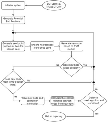
. Due to the non-holonomic nature of the system, the satellite orientation is controlled indirectly. The size of the configuration space is determined by the number of manipulator DoFs and the number of parameters required to describe the orientation of the servicing satellite. A new approach for trajectory planning by BiRRT is described by Algorithm 1. The flowchart of the proposed method is shown in Fig. 2. Algorithm’s functions will be explained in subsequent subsections.
Flowchart of the proposed BiRRT PVM algorithm.

Structure
 $\textbf{nodes}$
stores nodes from both trees. The structure can be considered as an array with two rows and the number of columns that depend on the number of nodes in trees (one additional node is one additional column). The function
 $\texttt{ConvertToNodesStructure}$
converts stand-alone point from the configuration space to
 $\textbf{nodes}$
structure by putting passed point in the proper row of the structure. Algorithm returns trajectory if a given distance between tress is achieved (in pseudocode described as
 $\delta$
).
We consider node as a vector which contains system’s configuration and the derivatives of configuration angles (in the case of satellite orientation, derivatives of Euler’s angles). Such vector can be expressed as:
 \begin{equation} {\textbf{X}_\textrm{node}}= \begin{bmatrix}{\dot{\textbf{q}}_\textrm{red}} \\[5pt]{\textbf{q}_\textrm{red}} \end{bmatrix} = \begin{bmatrix} \boldsymbol{{\dot{\Theta }}}_{s} \\[5pt] \boldsymbol{\dot{\theta }}_m \\[5pt] \boldsymbol{{\Theta }}_{s} \\[5pt] \boldsymbol{{\theta }}_m \end{bmatrix} \end{equation}

3.1. Potential end position
The potential end position (PEP) is a particular system’s configuration (including velocities) where the manipulator tip is in the desired position in the Cartesian space and the last link of the manipulator (the manipulator tip) has desired orientation. For each satellite orientation (provided that the inverse kinematics solution exists), it is possible to evaluate manipulator’s configuration which allows the manipulator tip to achieve the desired position in the inertial frame
 $\Pi _{\textrm{iner}}$
. Satellite CoM position depends on the manipulator’s configuration and satellite orientation. Hence, the traditional inverse kinematics will not work in such system. Every joint’s motion influences satellite position and orientation; thus, calculated angles in joints will not ensure that the manipulator tip will be in the desired point in the Cartesian space. In the free-floating case, PEPs can be calculated numerically or analytically (just for the basic planar case). In the numerical approach, kinematic constraint equations are given by:
 \begin{equation}{\textbf{F}_\textrm{pos}}(\boldsymbol{\theta }_m)= \textbf{r}_s(\boldsymbol{\theta }_m)+{\textbf{R}_s^{\textrm{iner}}}(\textbf{p}+\texttt{f}_\textrm{kin}(\boldsymbol{\theta }_m))-{\textbf{r}_\textrm{POI}}={\textbf{r}_\textrm{tip}}(\boldsymbol{\theta }_m)-{\textbf{r}_\textrm{POI}}=\mathbf{0} \end{equation}
 \begin{equation}{\textbf{F}_\textrm{ori}}(\boldsymbol{\theta }_m)=({\textbf{R}_{s}^{\textrm{iner}}}{\textbf{R}_\textrm{tip}^{s}}(\boldsymbol{\theta }_m))^T{\textbf{R}_\textrm{POI}^{\textrm{iner}}}=({\textbf{R}_\textrm{tip}^{\textrm{iner}}}(\boldsymbol{\theta }_m))^T{\textbf{R}_\textrm{POI}^{\textrm{iner}}}={\textbf{I}} \end{equation}
where
 $\textbf{F}_\textrm{pos}$
is a manipulator tip position constraint,
 $\textbf{F}_\textrm{ori}$
is an orientation constraint,
 $\texttt{f}_\textrm{kin}( \boldsymbol{\theta }_m)$
is a forward kinematics function, and
 $\textbf{r}_\textrm{POI}$
is the desired point given with respect to the inertial frame
 $\Pi _{\textrm{iner}}$
. The position of the satellite
 $\textbf{r}_s$
is calculated from Eq. (15). Equations (18) and (19) can be solved for instance by the Newton–Raphson method.
 $\textbf{R}_\textrm{tip}^{s}$
depends on
 $\boldsymbol{\theta }_{m}$
and can be derived as a part of the matrix
 $\textbf{T}_\textrm{tip,s}$
which is described as:
 \begin{equation}{\textbf{T}_{\textrm{tip},s}}=\prod _{i=0}^{n}\textbf{T}_{i,i-1} \end{equation}
where
 $i=0$
denotes the satellite and
 $\textbf{T}_{i,i-1}$
is matrix of homogeneous transformations dependent on Denavit–Hartenberg parameters corresponding to a particular joint [Reference Waldron, Schmiedeler, Siciliano and Khatib63].
PEPs can be computed for a certain range of the satellite orientation. Those points are used in BiRRT algorithm as first nodes of the second tree; thus, this procedure allows to control the final configuration of the system (second tree shown in Fig. 3). There are known solutions where one end configuration is the first node of the second tree in the free-floating system [Reference Rybus39], and there are also solutions where several target configurations are used as first nodes of the second tree in the fixed-base case [Reference Berenson, Srinivasa, Ferguson, Collet and Kuffner64, Reference Hirano, Kitahama and Yoshizawa65]. To the best of our knowledge, setting several target configurations as the first nodes of the second tree in the free-floating case is a new approach. This new solution allows to determine particular range of the final satellite orientation without limiting the number of potential end configurations. Thanks to that, it is more likely to achieve the desired manipulator tip position and orientation. Moreover, the designed algorithm keeps the functionality of choosing the approach based on just one node as the first node of the second tree. In Algorithm 1, PEPs calculation is represented by a function
 $\texttt{GeneratePEPs}$
.
 $\texttt{GeneratePEPs}$
function is described by Algorithm 2. After calculating, PEPs are saved in the structure
 $\textbf{nodes}$
as first nodes of the second tree [
 $\texttt{SaveNode}$
(
 $\textbf{nodes}$
,
 $\textbf{X}_\textrm{PEP}$
,
 $2$
)]. The values of derivatives of angles [which are part of nodes vectors as shown in Eq. (17)] in PEPs are equal to zero. This is because the aim of the trajectory planning is to stop the manipulator tip in the desired position. Computed values have to be checked if any of them leads to a collision with an obstacle or a collision inside the system. If yes, particular PEP is discarded and is not included in the second tree.
Second tree initiated by a set of PEPs.


3.2. Choosing seed point
Seed point is a point that allows the algorithm’s tree to grow. In the basic RRT algorithm, that point is a random point, chosen from the space
 $\mathcal{C}$
[Reference Kuffner and LaValle66]. In BiRRT algorithm, where in the space
 $\mathcal{C}$
there are two trees, certain nodes from trees can be seed points. It means that the algorithm is trying to find a pair of nodes (one node in each tree) that are closest to each other and allow the shortest connection between the trees. If algorithm wants to extend one of the trees, it chooses the nearest node from the second tree as a seed point. This step is performed every
 $\texttt{k}$
iterations, where
 $\texttt{k}$
is a constant value. The goal is to bring the two trees as close to each other as possible. In other situations, algorithm chooses a random point. Choosing seed point is the first step to extend the tree. The function which returns such point is represented in Algorithm 1 by function
 $\texttt{ReturnSeedPoint}$
which is described by Algorithm 3. Such algorithm refers to the ReturnNearest (Algorithm 4) function, but
 $\texttt{ReturnSeedPoint}$
uses both returned values. As arguments, object
 $\textbf{nodes}$
is passed twice.

Algorithm 3 strives to achieve the shortest possible distance between the trees in the space
 $\mathcal{C}$
. This distance should be understood as a relative “closeness” between nodes. Various metrics can be used for the measurement of distance [Reference LaValle, Kuffner, Donald, Lynch and Rus67]. We choose the following metric based on a weighted Euclidean distance for the satellite angular velocity, the angular velocity of manipulator joints, the orientation of the satellite and the angular positions of manipulator joints:
 \begin{equation} \texttt{d}=\zeta _1||\Delta \boldsymbol{\dot{\Theta }}_{s}||+\zeta _2 ||\Delta \boldsymbol{\dot{\theta }}_{m}||+\zeta _3||\Delta \boldsymbol{\Theta }_{s}||+\zeta _4||\Delta \boldsymbol{\theta }_{m}|| \end{equation}
where
 $\zeta _1$
,
 $\zeta _2$
,
 $\zeta _3$
and
 $\zeta _4$
are weights that have direct influence on which point will be described as the closest. The obtained distance is dimensionless. The shortest distance between the trees in the space
 $\mathcal{C}$
influences the final system’s configuration. Usually smaller distance between trees is a smaller error between the position and the orientation at the end of the trajectory and the desired one. The distance definition determines the node from which it will be easiest to reach the desired configuration [Reference Rybus39]. Equation (21) is used in every case where distance determination between two points in the configuration space is needed.

3.3. New node generation based on PVM method
The proposed approach guarantees that the system is able to reach every configuration described by nodes despite the fact that the system is non-holonomic. Node generation is shown by Algorithm 5.

To determine new node in the tree, system’s dynamic equations are used [Eqs. (2), (8) and (10)]. New state of the system depends on a value of the torque vector [Reference Rybus39]. Such vector refers just to the manipulator’s joints because the satellite orientation is not controlled directly [the orientation of the satellite depends on manipulator’s motion according to Eq. (8)].
Previous solutions were based on torques combination where calculation for every permutation had to be made [Reference Rybus and Seweryn34, Reference Rybus39]. Constant positive, negative and zero torque were used in every permutation. Torques were passed to the dynamics function which returned certain system’s configuration. Then, the algorithm checked which configuration is the closest one to the seed point and then saved it as a new node in the tree. The number of combinations depends on the the number of manipulator’s DoFs according to dependency
 $3^n$
. In order to provide higher efficiency, the new pseudo-velocities method (PVM) is proposed.
PVM is based on calculating torques in joints which allow to achieve the shortest distance between the new node in the space and the seed point. In other words, algorithm looks for control signals which bring the whole system from the configuration described by the closest node in the tree to the configuration described by the seed point. Due to the non-holonomic nature, it is difficult to calculate such torques which bring the system to the desired manipulator’s configuration and satellite orientation.
Calculations are performed in the configuration space
 $\mathcal{C}$
. PVM uses velocities to calculate joint control torques which carry the system to such configuration. When the algorithm chooses the nearest point in the tree to the seed point, it is possible to calculate pseudo-velocity that describes the desired velocity which is needed to proceed towards the seed point. Consider
 $\boldsymbol{{\textbf{X}}}_\textrm{seed}$
and
 $\boldsymbol{\textbf{X}}_\textrm{nearest}$
which denote seed point and the nearest node to that point in the tree, respectively. The pseudo-velocity vector can be calculated as:
 \begin{equation} \boldsymbol{\dot{\textbf{q}}}_\textrm{pv}= \begin{bmatrix}{{\boldsymbol{\dot{\Theta }}}_\textrm{pv}}_s\\[5pt]{{\boldsymbol{\dot{\theta }}}_\textrm{pv}}_m \end{bmatrix} = \textrm{G}_1\left ( \begin{bmatrix}{\boldsymbol{{\Theta }}_\textrm{seed}}_s \\[5pt]{\boldsymbol{{\theta }}_\textrm{seed}}_m \end{bmatrix} - \begin{bmatrix}{\boldsymbol{{{\Theta }}}_\textrm{nearest}}_s \\[5pt]{\boldsymbol{{\theta }}_\textrm{nearest}}_m \end{bmatrix}\right ) \end{equation}
where
 $\textrm{pv}$
subscript refers to the pseudo-velocity,
 $\textrm{G}_1$
is a gain higher than 0,
 ${\boldsymbol{{\Theta }}_\textrm{seed}}_s$
and
 ${\boldsymbol{{\theta }}_\textrm{seed}}_m$
is a system’s configuration from seed point
 $\textbf{X}_\textrm{seed}$
,
 ${\boldsymbol{{\Theta }}_\textrm{nearest}}_s$
and
 ${\boldsymbol{{\theta }}_\textrm{nearest}}_m$
is a system’s configuration from the nearest node
 $\textbf{X}_\textrm{nearest}$
. The value of the gain
 $\textrm{G}_1$
can be constant or variable and change depending on the distance between two trees. The next step is to find the values of the derivatives of satellite’s orientation angles and joint angles which are achievable for the system and allow to get closer to the velocities described by
 $\boldsymbol{\dot{\textbf{q}}}_\textrm{pv}$
. Such achievable derivatives’ vector can be described as a function
 $\textrm{g}$
:
 \begin{equation} \textrm{g}=||\boldsymbol{\dot{\Theta }}_s-{\boldsymbol{\dot{\Theta }}_\textrm{pv}}_s||+||\boldsymbol{\dot{\theta }}_{m}-{\boldsymbol{\dot{\theta }}_\textrm{pv}}_m|| \end{equation}
Equation (23) is similar to Eq. (21) but with
 $\zeta _3=\zeta _4=0$
and
 $\zeta _1=\zeta _2=1$
. In Eq. (23),
 $\textrm{g}$
is a scalar value and
 $\boldsymbol{\dot{\Theta }}_s$
and
 $\boldsymbol{\dot{\theta }}_{m}$
denote vectors which describe temporary angular velocities. In Eq. (23),
 $\boldsymbol{\dot{\theta }}_{m}$
is known, but
 $\boldsymbol{\dot{\Theta }}_s$
has to be calculated. Satellite orientation and its derivatives depend on the manipulator’s configuration and joint’s velocities, thus vector
 $\boldsymbol{\dot{\Theta }}_s$
= f(
 $\boldsymbol{\dot{\theta }}_{m}$
,
 $\boldsymbol{{\theta }}_{m}$
). The function
 $\textrm{f}$
is a dynamic equation which returns value of
 $\boldsymbol{\dot{\Theta }}_s$
. Returned value depends on actual joint’s angular velocities. Required torques can be determined based on returned velocities:
 \begin{equation} \boldsymbol{\textbf{u}}=\texttt{G}_u(\boldsymbol{\dot{\theta }}_{m}-{\boldsymbol{\dot{\theta }}_\textrm{pv}}_m) \end{equation}
where
 $\texttt{G}_u$
is a gain higher than 0 that influences the torque values. The calculations are described by Algorithm 6.


3.4. Tree connection
In order to determine the trajectory, the algorithm tries to merge two trees. In fact, perfect merging is impossible. The straight line trajectory in the configuration space for the free-floating case is not feasible in contrast to the fixed-base case [Reference Qureshi and Ayaz68]. This is why the algorithm should bring both trees as close as possible, and then connection should be initialised.
In this case, the procedure is to define a vector between positions in the configuration space of the two nearest nodes (points in configuration space) in two trees. Then, every node from the second tree should be moved by that vector. This process guarantees that the final trajectory will be feasible. The process is shown in Fig. 4.
Tree connection procedure in the configuration space (two-dimensional configuration space).

By joining trees, we implement an offset in that part of the trajectory which comes from the second tree. If we realise the trajectory obtained from this connection, then the satellite orientation trajectory will be different than if we use trajectory from the second tree without the shift. To get valid satellite orientation, for every manipulator’s configuration in the second tree, orientation recalculation has to be made. Due to the offset introduced in order to connect two trees and to obtain continuous trajectory, the tip of the manipulator achieves the desired position and orientation with some error. This is one of the disadvantages of using the bidirectional RRT algorithm for non-holonomic systems [Reference Lamiraux, Ferré and Vallée69].
3.5. Trajectory smoothing
Due to the sharpness of the trajectory, the trajectory should be smoothed for practical reasons. The smoothing method presented in ref. [Reference Rybus, Seweryn, Tchon and Zielinski70] is used. The trajectory obtained from the BiRRT PVM algorithm may require rapid accelerations of the manipulator and high control torques. Thus, the first task of the trajectory smoothing algorithm is to modify the distribution of points that define the trajectory in the joint space. This step is necessary because the feasible trajectory should include the acceleration phase at the beginning of motion and the deceleration phase at the end of motion. Such approach reduces the required control torques. The distances between subsequent points in the new distribution are determined by the cosine function. For the trajectory composed of
 $n_p$
points, the distance (along this trajectory) between the i-th and (i
 $+1$
)-th point is defined by the following relation:
 \begin{equation} \sigma _{i/i+1} = 1 + \cos\bigg (2\pi \frac{i}{n_p + 1} + \pi \bigg ) \end{equation}
After the calculation of distances between all subsequent points, it is possible to perform linear interpolation of each component of the given trajectory.
The second task of the trajectory smoothing algorithm is to change the shape of the trajectory to obtain smoother motion of joints. The algorithm moves through subsequent points that form the trajectory in the joint space. Point i-th and
 $(i + z)$
-th form a straight line (z is a given natural number). All points that lie between the i-th and
 $(i + z)$
-th point are moved to this straight line:
 \begin{equation} (\boldsymbol{\theta }_{m})_{i+j} = (\boldsymbol{\theta }_{m})_i + j\cdot [(\boldsymbol{\theta }_{m})_{i+z} - (\boldsymbol{\theta }_{m})_i]/z \end{equation}
where
 $(\boldsymbol{\theta }_{m})_k$
is a position of k-th point of the trajectory, while
 $j = 1, \ldots, z$
. After the last point of the trajectory is reached, the algorithm can go back to the first point and the next iteration could begin. The number of needed iterations depends on the choice of z and on the shape of the original trajectory (the higher number of iterations is required for more complicated shape). Smoothing procedure is shown in Fig. 5.
Trajectory smoothing. Picture (a) shows generated trajectory (red) and prepared smoothed trajectory (dashed green); picture (b) shows smoothed final trajectory.

3.6. Collision detection
During calculations for every new node that will be added, the algorithm checks if such configuration causes a collision between obstacle, manipulator’s links and satellite. For every node, algorithm calculates the position of the satellite, joints and the manipulator tip relative to the inertial frame
 $\Pi _{\textrm{iner}}$
. Algorithm calculates such coordinates and passes the data to the function which checks if collision occurs. Manipulator’s links can be treated as endlessly thin. Because of this simplification, it is necessary to virtually increase the size of the obstacles. The function that detects collisions is described by Algorithm 8.

In Algorithm 8, geometry includes links’ length and satellite size. The object
 $\textbf{X}_\textrm{new}$
is passed as an argument to the function which calculates satellite, joints and manipulator tip position in the Cartesian reference frame. Firstly, the algorithm checks if any collision inside the system occurs. If yes, function returns status which informs that the new node cannot be added to the tree. Obstacles’ positions are known; thus, function can also check if there is any collision between system and obstacles.
To determine the collision between the system and obstacles, the spatial case can be considered. Collision detection is based on basic linear algebra [Reference Redon, Kheddar and Coquillart71]. Plane equation, where
 $\boldsymbol{\vec{\textbf{n}}}(\texttt{A}, \texttt{B}, \texttt{C})$
is a versor perpendicular to the plane and
 $\textbf{P}(\texttt{x}_0, \texttt{y}_0, \texttt{z}_0)$
is a point which lays on the plane, is described as:
 \begin{equation} \pi :\texttt{A}(\texttt{x}-\texttt{x}_0)+\texttt{B}(\texttt{y}-\texttt{y}_0)+\texttt{C}(\texttt{z}-\texttt{z}_0)=0 \end{equation}
 \begin{equation} {\vec{\textbf{n}}}=\left ({\frac{\textbf{P}_1-\textbf{P}_s}{||\textbf{P}_1-\textbf{P}_s||}}\right )\times \left ({\frac{\textbf{P}_2-\textbf{P}_s}{||\textbf{P}_2-\textbf{P}_s||}}\right )={\vec{\textbf{n}}}_1\times {\vec{\textbf{n}}}_2 \end{equation}
To determine those vectors, three points are needed as it is shown in Fig. 6.
Plane with two vectors and plane’s versor.

Any line in space can be described by two planes, where planes have to be different. Line equation can be described by a system of planes’ equations:
 \begin{equation} \begin{cases} \pi _1:\texttt{A}_1(\texttt{x}-\texttt{x}_1)+\texttt{B}_1(\texttt{y}-\texttt{y}_1)+\texttt{C}_1(\texttt{z}-\texttt{z}_1)=0 \\[5pt] \pi _2:\texttt{A}_2(\texttt{x}-\texttt{x}_2)+\texttt{B}_2(\texttt{y}-\texttt{y}_2)+\texttt{C}_2(\texttt{z}-\texttt{z}_2)=0 \end{cases} \end{equation}
Line versor
 ${\vec{\textbf{e}}}_p$
, two points on both planes (
 $\textbf{P}_1(\texttt{x}_1,\texttt{y}_1,\texttt{z}_1)$
and
 $\textbf{P}_2(\texttt{x}_2,\texttt{y}_2,\texttt{z}_2)$
) and point
 $\boldsymbol{\textbf{P}}_s$
which lays on the line are needed to calculate
 ${\vec{\textbf{n}}}_1$
and
 ${\vec{\textbf{n}}}_2$
(where
 $\boldsymbol{\textbf{P}}_1$
and
 $\boldsymbol{\textbf{P}}_2$
have to meet the condition
 $\boldsymbol{\textbf{P}}_1\neq \boldsymbol{\textbf{P}}_2$
). Those points can be constant. Thanks to Eq. (29), it is possible to check if particular point lays on the line (equation value equal to zero). Described points and vectors are shown in Fig. 7.
Line described by two planes.

Obstacles are treated as cubes. Every cube has six walls which can be described by six planes. Every plane’s normal versor
 ${\vec{\textbf{n}}}$
points outward the cube. Thus, if point substituted into plane’s equation is inside the obstacle, each of the six equations (one for every cube’s wall) returns negative value. Cube with normal versors is shown in Fig. 8.
Obstacle’s planes.

To detect collision, cross points have to be calculated. To do that, particular obstacle plane equation has to be added to Eq. (29). Hence, to determine the intersection point
 $\boldsymbol{\textbf{P}}_i$
, system of equations has to be solved:
 \begin{equation} \begin{cases} \pi _1:\texttt{A}_1(\texttt{x}-\texttt{x}_1)+\texttt{B}_1(\texttt{y}-\texttt{y}_1)+\texttt{C}_1(\texttt{z}-\texttt{z}_1)=0 \\[5pt] \pi _2:\texttt{A}_2(\texttt{x}-\texttt{x}_2)+\texttt{B}_2(\texttt{y}-\texttt{y}_2)+\texttt{C}_2(\texttt{z}-\texttt{z}_2)=0 \\[5pt] \pi _3:\texttt{A}_3(\texttt{x}-\texttt{x}_3)+\texttt{B}_3(\texttt{y}-\texttt{y}_3)+\texttt{C}_3(\texttt{z}-\texttt{z}_3)=0 \end{cases} \end{equation}
For each obstacle’s plane, normal versor is described as
 ${\vec{\textbf{n}}_3}(\texttt{A}_3, \texttt{B}_3, \texttt{C}_3)$
and the point which lays on the obstacle is
 ${{\textbf{P}}_3}(\texttt{x}_3, \texttt{y}_3, \texttt{z}_3)$
. The system of equations presented in Eq. (30) can be represented in the matrix form:
 \begin{equation} \boldsymbol{\textbf{P}}_i = \begin{bmatrix} \texttt{x} \\[5pt] \texttt{y} \\[5pt] \texttt{z} \end{bmatrix} = \textbf{G}^{-1}\textbf{b} \end{equation}
 \begin{equation} \boldsymbol{\textbf{G}} = \begin{bmatrix} \texttt{A}_1 \;\;\;\;\; & \texttt{B}_1\;\;\;\;\; & \texttt{C}_1 \\[5pt] \texttt{A}_2\;\;\;\;\; & \texttt{B}_2\;\;\;\;\; & \texttt{C}_2 \\[5pt] \texttt{A}_3\;\;\;\;\; & \texttt{B}_3\;\;\;\;\; & \texttt{C}_3 \end{bmatrix} \end{equation}
 \begin{equation} \boldsymbol{\textbf{b}} = \begin{bmatrix} \texttt{A}_1\texttt{x}_1 + \texttt{B}_1\texttt{y}_1 + \texttt{C}_1\texttt{z}_1\\[5pt] \texttt{A}_2\texttt{x}_2 + \texttt{B}_2\texttt{y}_2 + \texttt{C}_2\texttt{z}_2\\[5pt] \texttt{A}_3\texttt{x}_3 + \texttt{B}_3\texttt{y}_3 + \texttt{C}_3\texttt{z}_3 \end{bmatrix} \end{equation}
After calculation,
 $\boldsymbol{\textbf{P}}_i$
has to be modified:
 \begin{equation} {{\tilde{\textbf{P}}}}_i = \boldsymbol{\textbf{P}}_i+ {\vec{\textbf{e}}}_p\delta \end{equation}
where
 $\delta$
is a small value. The aim of this procedure is to check if collision really appears by moving calculated point a little bit inside the obstacle. Original
 $\boldsymbol{\textbf{P}}_i$
lays on the plane
 $\pi _3$
; thus, this plane’s equation returns value 0 if original
 $\boldsymbol{\textbf{P}}_i$
would be substituted. Thanks to that, if
 ${{\tilde{\textbf{P}}}}_i$
will be inside the obstacle, every obstacle’s plane returns negative value. If not, collision does not occur. In the considered case, every manipulator’s link is treated as a line segment. Hence,
 $||\boldsymbol{\textbf{P}}_i-\boldsymbol{\textbf{P}}_s||\lt \texttt{L}_\textrm{link}$
condition has to be met, where
 $\texttt{L}_\textrm{link}$
is particular link length. If any condition is met, the collision exists for certain system’s configuration. Collision with obstacle is shown in Fig. 9.
Finding intersection point
 $\boldsymbol{\textbf{P}}_i$
.

4. Results
To verify the proposed BiRRT PVM method, a simulation tests campaign was conducted. Two scenarios were considered during tests. Trajectory planning was performed on a PC computer with Intel Core i7-8550U and 32 GB RAM using Matlab implementation of the algorithm. The trajectory set was generated, and each trajectory correctness was checked in simulations based on the system’s dynamic model. In order to show the advantages of the BiRRT PVM method, the generated trajectories were compared with those generated by other algorithms: BiRRT algorithm with torque permutation and RRT algorithm with the discussed PVM method [Reference Rybus and Seweryn34, Reference Rybus39].
One of the BiRRT PVM trajectories was performed on a planar air-bearing microgravity simulator [Reference Basmadji, Chmaj, Rybus and Seweryn49]. The trajectory was planned before the execution of the manoeuvre on the test bed. In trajectory generator software, actual test set-up parameters were used. The purpose of the microgravity simulator tests was to demonstrate that the proposed trajectory planning method can be applied in practice on a real satellite-manipulator system that works in microgravity conditions.
The simulation results are presented in Sections 4.2 and 4.3. For both scenarios, the trajectory was not smoothed. Trajectory tested on microgravity simulator was smoothed (as presented in Fig. 5). The trajectory planning was repeated 20 times for each algorithm. The execution time for each trajectory was set to
 $t_f=30\,\textrm{s}$
. The presented results refer to the planar case. However, the equations presented in Section 2 can be used for the spatial case as well.
During the simulations, the weights values from Eq. (21) were equal to
 $\zeta _1=\zeta _2=\zeta _3=\zeta _4=1$
.
4.1. Satellite-manipulator system parameters
In order to perform path planning for the free-floating manipulator, dynamic parameters of the system must be known and implemented in the algorithm. Such parameters include the mass, the inertia tensor and the position of the CoM for each manipulator’s link as well as the mass and the inertia tensor of the satellite. Therefore, the identification of parameters of the satellite-manipulator system operated on the air-bearing table was performed for the purposes of this work. The system is planar; thus, only the following parameters are needed for the trajectory planning algorithm: masses, moments of inertia around the axis perpendicular to the plane of motion as well as X and Y components of the CoM position vectors. The identification was executed by hanging each link independently on strings and analysing the natural oscillations around the equilibrium point. Parameters of the satellite mock-up were identified analogously using the air-bearing table. The satellite mock-up parameters are shown in Table I, whereas the manipulator’s parameters are depicted in Table II.
Satellite’s geometric and mass parameters.

Manipulator’s geometric and mass parameters.

4.2. Scenario A
This scenario is a simple one. The scenario is presented in Fig. 10. The satellite is denoted symbolically as a square, and the initial manipulator joint positions are within limits. Thus, no collision occurs between the satellite and the manipulator. In the Cartesian space, there is one square obstacle and its centre is in
 $\textbf{p}_1=\begin{bmatrix} 1\, \textrm{m} & -0.15\,\textrm{m}\\ \end{bmatrix}^{T}$
. The obstacle is rotated by
 $45^{\circ }$
around the axis perpendicular to the plane of motion. The size of the obstacle is 0.17 m x 0.17 m. The
 $\Pi _{\textrm{iner}}$
is located in the initial position of
 $\Pi _s$
. The initial value of the state vector is
 $\textbf{v}_s(t=0)=\mathbf{0}$
,
 $\textbf{r}_s(t=0)=\mathbf{0}$
,
 ${\omega }_s(t=0)=0$
,
 $\Theta _s(t=0)=0$
,
 $\boldsymbol{\dot{\theta }}_{m}(t=0)=\boldsymbol{0}$
,
 $\boldsymbol{\theta }_{m}(t=0)=\begin{bmatrix} 96.2^{\circ } & -136.2^{\circ } & -20^{\circ }\\ \end{bmatrix}^{T}$
. The initial position of the manipulator tip is
 $\textbf{r}_\textrm{tip}(t=0)=\begin{bmatrix} 0.85\, \textrm{m} & -0.15\,\textrm{m}\\ \end{bmatrix}^{T}$
, and the initial orientation of the last manipulator link (the manipulator tip) is
 $\theta _\textrm{tip}=-60^{\circ }$
.
Scenario A presentation using one of the generated trajectories; the presented trajectory was generated using BiRRT PVM algorithm (initial configuration of the system is marked with blue colour, while the final configuration of the system is marked with green colour).

The aim of the algorithm was to find a collision-free trajectory that will bring the manipulator tip from the initial position to the Point Of Interest
 $\textbf{r}_\textrm{POI}=\textbf{r}_\textrm{tip}(t=30\,\textrm{s})=\begin{bmatrix} 1.2\,\textrm{m} & -0.15\,\textrm{m}\\ \end{bmatrix}^{T}$
. Additionally, the manipulator tip should have the final orientation equal to
 $\theta _\textrm{POI}=\theta _\textrm{tip}(t=30\,\textrm{s})=-60^{\circ }$
. Moreover, the final satellite orientation for the beginning of the second tree is chosen from the range
 $\lt -20^{\circ };20^{\circ }\gt$
. The last condition can only be met by BiRRT algorithm. RRT algorithm does not control the satellite orientation.
Results of the simulations are presented in Table III (BiRRT PVM), Table IV (BiRRT torque permutation) and Table V (RRT PVM). Table VI summarises the results of each algorithm for 75,000 iterations case.
Scenario A results for BiRRT PVM method.

Scenario A results for BiRRT torque permutation method.

Scenario A results for RRT PVM method.

Scenario A results comparison for 75,000 iterations.

In the results’ tables, parameter Number of iterations refers to the trajectory generator and determines how many repetitions the main program loop has done to get the given results. In the software, a condition for the end of the program is the number of iterations. The tables show the results for 10,000, 25,000 and 75,000 iterations. Parameter Number of nodes refers to the number of the nodes in the configuration space. In RRT algorithm, the maximum number of the nodes is the number of iterations. In BiRRT case, the maximum number of nodes is twice the number of iterations. This is because during one iteration both trees growth is performed. Practically, the number of nodes is always lower than number of iterations. It is because some nodes are discarded due to failure to meet at least one of the conditions.
Parameter Manipulator tip position error refers to the difference between the position of the manipulator tip at the end of the trajectory and Point Of Interest
 $\textbf{r}_\textrm{POI}$
. Manipulator tip orientation error refers to the absolute value of the difference between the manipulator tip orientation at the end of the trajectory and the desired orientation.
The above results show that increasing the number of iterations significantly affects the generation of trajectories. In addition, it influences the configuration space coverage (number of nodes in the configuration space) and in BiRRT case has fair impact on the distance between two trees. Those results also show that increasing the number of iterations does not necessarily cause lower errors of the manipulator tip position or the manipulator tip orientation. For instance, in RRT PVM results in Table V, the maximum and the average manipulator tip orientation error in the 75,000 iterations case is greater than the error in the 25,000 iterations case. This result is caused by the fact that the RRT algorithm chooses the nearest node based on a distance defined as follows:
 \begin{equation} \texttt{d}_{c}=\xi _1||\Delta \textbf{d}_\textrm{tip}||+\xi _2 \Delta{{\theta }}_\textrm{tip} \end{equation}
where
 $\xi _1$
and
 $\xi _2$
are weights,
 $\Delta \textbf{d}_\textrm{tip}$
is the manipulator tip position error and
 $\Delta \theta _\textrm{tip}$
is the manipulator tip orientation error.
This relation is dependent on the manipulator tip position error as well as the manipulator tip orientation error. The applied weights can be chosen in a way that one of the errors is strengthened in the distance definition and therefore causes the other error to be larger despite increasing the number of iterations.
There are two distance definitions in RRT case. The first one describes distance in the configuration space [Eq. (21)], and the second one describes distance defined as shown above. This is because, in RRT case, algorithm does not know the configuration that will lead to the given manipulator tip position and orientation. Thus, to achieve given requirements, the Cartesian distance definition is derived in Eq. (35).
Equation (35) is used to determine the last configuration in the trajectory which is described by one of the nodes in the configuration space. The presented RRT PVM results were generated with the Cartesian distance definition weights equal to
 $\xi _1=\xi _2=1$
.
Table VI shows that BiRRT PVM in some cases is much better than algorithm which does not use the PVM method. In this scenario, BiRRT PVM method achieved worse results just in the manipulator tip orientation requirement.
Consider BiRRT PVM and RRT PVM results. The average manipulator tip position error in BiRRT PVM case is equal to 0.0172 m and the average manipulator tip orientation error in the same case is equal to 0.0248 rad which is equal to 1.421
 $^{\circ }$
. The average manipulator tip position error in RRT PVM case is equal to 0.0460 m and average manipulator tip orientation error in the same case is equal to 0.0162 rad which is equal to 0.928
 $^{\circ }$
. It shows that RRT PVM algorithm in Scenario A is doing better with the manipulator tip final orientation and worse with the manipulator tip final position. Therefore, it does not mean that the trajectory generated by RRT PVM algorithm will achieve high manipulator tip orientation and position accuracy at the same time.
Tables III, IV, V and VI provide an estimation of the computing time for each algorithm. This is the time needed by the algorithm to reach the given number of iterations. The Matlab implementations of the considered algorithms have not been optimised for speed, so the resulting values are high. However, it is possible to perform comparison between different algorithms and different numbers of iterations. It can be observed that computing time increases non-linearly as the number of iterations increases. As shown in Table VI, for 75,000 iterations, the average computing time for the BiRRT PVM algorithm is
 $52.46\%$
shorter than the average computing time for the BiRRT with torque permutation. This is caused by the fact that in the torque permutation methods, all combinations of control torques must be checked during construction of each new node of the tree. On the other hand, the average computing time of the RRT PVM algorithm is significantly shorter than that of the BiRRT PVM algorithm due to the fact that only one tree is constructed in the RRT PVM algorithm.
The manipulator tip ’s position and orientation errors are shown in Fig. 11. The presented results are for all generated BiRRT trajectories. Three example trajectories in the Cartesian space are shown in Fig. 12. Each trajectory was generated by a different algorithm. Figure 13 depicts joints’ position for each trajectory presented in Fig. 12. The final joints’ position can be different due to the fact that the final satellite orientation in each trajectory can be different. Figure 14 shows the manipulator tip orientation for each trajectory versus time.
BiRRT PVM and BiRRT torque permutation comparision.

The manipulator tip trajectories generated by different algorithms and methods.

Joints’ position for Scenario A.

The manipulator tip orientation for Scenario A.

4.3. Scenario B
This scenario is a difficult one. The scenario is presented in Fig. 15. In the Cartesian space, there are four rectangular obstacles and their centres are in points:
 $\textbf{p}_1=\begin{bmatrix} 0.65\,\textrm{m}\;\;\;\; & 0.1\,\textrm{m}\\ \end{bmatrix}^{T}$
,
 $\textbf{p}_2=\begin{bmatrix} 1\,\textrm{m}\;\;\;\; & 0.4\,\textrm{m}\\ \end{bmatrix}^{T}$
,
 $\textbf{p}_3=\begin{bmatrix} 1\,\textrm{m}\;\;\;\; & -0.6\,\textrm{m}\\ \end{bmatrix}^{T}$
,
 $\textbf{p}_4=\begin{bmatrix} 1.5\,\textrm{m}\;\;\;\; & 0\,\textrm{m}\\ \end{bmatrix}^{T}$
. The sizes of the obstacles are 0.1 m x 0.15 m, 0.2 m x 0.2 m, 0.2 m x 0.2 m and 0.4 m x 0.2 m, respectively. The obstacles are rotated by the following angles around the axis perpendicular to the plane of motion:
 ${\alpha }_1=0^{\circ }$
,
 ${\alpha }_2=45^{\circ }$
,
 ${\alpha }_3=45^{\circ }$
,
 ${\alpha }_4=45^{\circ }$
.
Scenario B presentation using one of the generated trajectories (initial configuration of the system is marked with blue colour, while the final configuration of the system is marked with green colour).

The
 $\Pi _{\textrm{iner}}$
is located in the initial position of the
 $\Pi _s$
. The initial value of the state vector is
 $\textbf{v}_s(t=0)=\mathbf{0}$
,
 $\textbf{r}_s(t=0)=\mathbf{0}$
,
 ${\omega }_{s}(t=0)=0$
,
 $\Theta _s(t=0)=0$
,
 $\boldsymbol{\dot{\theta }}_{m}(t=0)=\boldsymbol{0}$
,
 $\boldsymbol{\theta }_{m}(t=0)=\begin{bmatrix} -7.1^{\circ } & -91.4 ^{\circ } & 143.5^{\circ } \\ \end{bmatrix}^{T}$
. The initial position of the manipulator tip is
 $\textbf{r}_\textrm{tip}=\begin{bmatrix} 1\,\textrm{m}\;\;\;\; & -0.25\,\textrm{m}\\ \end{bmatrix}^{T}$
, and the initial manipulator tip orientation is
 $\theta _\textrm{tip}=45^{\circ }$
.
The aim of the algorithm was to find a collision-free trajectory that will bring the manipulator tip from the initial position to the Point Of Interest
 $\textbf{r}_\textrm{POI}=\textbf{r}_\textrm{tip}(t=30\,\textrm{s})=\begin{bmatrix} 0.7\,\textrm{m}\;\;\; & 0.28\,\textrm{m}\\ \end{bmatrix}^{T}$
. Additionally, the manipulator tip should have the final orientation equal to
 $\theta _\textrm{POI}=\theta _\textrm{tip}(t=30\,\textrm{s})=120^{\circ }$
. Moreover, the final satellite orientation for the beginning of the second tree is chosen from the range
 $\lt -20^{\circ };20^{\circ }\gt$
.
Due to the complexity of the scenario, RRT PVM and BiRRT with torque permutation were not able to generate any proper trajectory. Therefore, Table VII presents the results only for the BiRRT PVM algorithm. In this scenario, the advantage of the proposed method over the BiRRT with torque permutation and RRT PVM algorithms is clearly visible. The BiRRT PVM algorithm has the ability to solve more challenging trajectory planning problems.
Scenario B results for BiRRT PVM method.

As in the case of Scenario A, more iterations have positive impact on the generated trajectories. For the 75,000 iterations case, the average manipulator tip position error is equal to 0.0215 m and average manipulator tip orientation error is 0.0326 rad which is 1.868
 $^\circ$
. Taking into consideration the fact that other algorithms were not able to achieve such results in this scenario, BiRRT PVM is significantly more universal than other algorithms. The BiRRT PVM error results in Scenario B and in 75,000 iteration case are similar to the results from the Scenario A. The average computing time of Bi-RRT PVM algorithm in Scenario B is not longer than the average computing time in Scenario A, despite the fact that in Scenario B we have four obstacles, while in Scenario A only one obstacle was considered.
4.4. Results from the air-bearing microgravity simulator
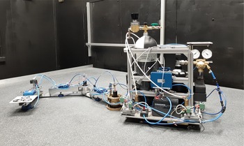
The Scenario B was validated in the test campaign performed in simulated microgravity conditions on the planar air-bearing simulator. Such simulators are widely used for validation of control algorithms and trajectory planning methods in the field of space robotics [Reference Rybus and Seweryn72]. However, the presented test campaign is the first such test demonstration of the RRT algorithm for the space manipulator. The experiments were performed on the planar air-bearing microgravity simulator operated at the Space Research Centre of the Polish Academy of Sciences [Reference Basmadji, Chmaj, Rybus and Seweryn49]. This test bed consists of a flat granite table. The mock-up of the satellite-manipulator system is mounted on planar air-bearings (three air-bearings support the servicing satellite mock-up, while each link of the manipulator is supported by one air-bearing). These bearings use a thin film of pressurised air to provide frictionless motion on the table surface. In this simulator, the air is provided from the air tank located on the servicing satellite mock-up. All communication is wireless and electronics are powered by a battery. This allows to obtain the free-floating conditions in two dimensions (in the plane of the granite table surface). Each joint of the manipulator is controlled by a DC motor. The on-board computer on the servicing satellite mock-up is based on ATSAMA5D36. The schematic diagram of the satellite-manipulator system operated on the planar air-bearing microgravity simulator is shown in Fig. 16, while the photo of this system is presented in Fig. 17.
Schematic diagram of the satellite-manipulator system operated on the planar air-bearing microgravity simulator.

Photo of the satellite-manipulator system used in experiments.

The joint space path associated with the trajectory presented in Fig. 15 was reproduced five times. During each experiment, the control system implemented on the on-board computer and joint drivers were responsible for tracking the desired joint space trajectory of the manipulator with the use of measurements from the absolute optical encoders located in manipulator joints. Joints operated in the position control mode in which PID controllers ensure the closed-loop control. The position and orientation of the base and the manipulator tip are measured via the external vision system and two dedicated markers mounted on the satellite mock-up and the manipulator tip. No real tool was used in the experiment. Measurements from encoders are provided with the frequency of 100 Hz, whereas the measurements from the vision system are provided with the frequency of 20 Hz. The vision system measurements are not used by the closed-loop control system. They only provide the information about the system’s configuration in further analysis. As the granite table might not be levelled perfectly, the small gravitational drift influences the position of the satellite mock-up and the manipulator tip. Therefore, results for the position of markers are corrected with constant acceleration of
 $10^{-4}$
m
 $\cdot$
s
 $^{-2}$
in negative X and positive Y direction. Due to potential danger, no physical obstacles were used in the experiments. The initial orientation of the satellite mock-up was approximately the same in each test. In order to allow comparison of each trajectory, the results for the satellite and manipulator tip orientation were shifted towards the same starting point.
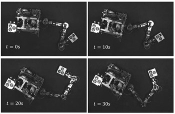
The planar spacecraft equipped with 3-DoF manipulator during performed experiments is shown in Fig. 18. The joint space path corresponding to the trajectory planned for Scenario B is presented in Fig. 19. The position of the manipulator tip is presented in Fig. 20, whereas its 2D trajectory is shown in Fig. 21. The orientation of the manipulator tip is depicted in Fig. 22. The orientation of the satellite mock-up is depicted in Fig. 23. Table VIII contains final values obtained in the experiments for the position and orientation of the manipulator tip as well as the orientation of the satellite mock-up. The errors for the above-mentioned values with respect to the desired values implemented in the planning algorithm are presented in Table IX. The Reference column in Tables VIII and IX refers to the errors resulting from the BiRRT PVM trajectory planning.
Frames captured by the camera mounted above the granite table that show the free-floating spacecraft equipped with the 3-DoF manipulator during experiments performed on the planar air-bearing microgravity simulator.

Joint positions for the selected trajectory from Scenario B.

The manipulator tip positions obtained in experiments.

The manipulator tip trajectories obtained in experiments.

The manipulator tip orientation obtained in experiments.

The satellite orientation obtained in experiments.

Results obtained in the experiments performed on the air-bearing microgravity simulator.

Errors obtained in the experiments performed on the air-bearing microgravity simulator.

The results of the test campaign show successful realisation of the path planned with the proposed algorithm. The experiments allowed to conclude about the feasibility of the trajectory. All five test results turned out to be close to the reference case achieved from the simulation. It is observed that one of the results crossed the safe zone of one of the obstacles, but it did not hit it. However, each results set is characterised with non-zero error with respect to the reference trajectory. The largest final manipulator tip position error (evaluated as the norm of the position error vector) was observed to be 0.1259 m, whereas the average error was 0.0773 m. The final manipulator tip orientation error varied from −9.2465
 $^{\circ }$
to 4.0545
 $^{\circ }$
, and the average error is observed to be −2.2491
 $^{\circ }$
. These deviations from the reference trajectory might be caused by disturbances appearing on the granite table. First of all, the levelling of the table was not perfect causing the system to drift due to gravitational acceleration. It is observed that the X position errors were larger for positive values and the Y position errors were larger for negative values. This indicates that the levelling of the table was deviated towards certain direction. Although constant acceleration was used as a correction for the results, the actual levelling profile of the table might be position-dependent causing the gravitational acceleration acting on the system to change with time. In addition, it is worth noting that the control system allowed to track the joint space trajectory; thus, no compensation of the manipulator tip position and orientation errors are possible. Finally, the identification of the geometric and mass parameters of the system used in the path planning algorithm might be imprecise. Moreover, the obtained trajectory is quite complicated and lasts relatively long duration of time; thus, the trajectory error sensitivity might be quite large. Nonetheless, the obtained experiment results are satisfactory and presented the feasibility of the trajectory.
5. Conclusions
In this paper, we have proposed an application of the BiRRT algorithm for planning a collision-free trajectory of the manipulator mounted on the free-floating satellite. In the considered case, the dynamic equations of the satellite-manipulator system must be used during the trajectory planning stage. The proposed approach is based on a new method for the construction of nodes of the trajectory tree. The novelty of the method includes evaluating torques in manipulator joints using pseudo-velocities method (PVM) that allows to achieve higher efficiency of the algorithm. The PVM method can be used in both RRT and BiRRT algorithms. In addition, the PEPs are introduced in the BiRRT algorithm in order to allow the second tree to begin from the set of desired potential configurations of the system (configurations in which the manipulator tip is in the desired position and has the desired orientation). Simulations based on the system’s dynamic equations in the simplified planar case allowed to validate the proposed method. The newly introduced BiRRT PVM method was compared with the RRT PVM and BiRRT torque permutation methods. The proposed modified BiRRT algorithm turned out to give better results than previous algorithms and allowed to improve the efficiency of the trajectory planning. The proposed method allows to solve the trajectory planning problem in difficult scenarios where other methods fail.
In addition, experiments on the planar air-bearing microgravity simulator were performed in order to analyse the practical applicability of the proposed algorithm. It is the first demonstration of the trajectory planning using the BiRRT algorithm for a manipulator working in simulated microgravity conditions. The errors for the final values of the manipulator tip position and orientation obtained in the experiments were relatively small, proving the feasibility of the planned trajectory. However, some problems characterising the RRT trajectory planning methods remain challenging. Although the computational time needed to solve the trajectory planning problem with the proposed Bi-RRT PVM method is much shorter than the time needed by Bi-RRT with torque permutation; this time is still significant. Other trajectory planning methods, in particular methods based on the APF, may require shorter computing time. Moreover, the non-honolomic nature of the manipulator mounted on the satellite (system state is dependent on the trajectory) results in the necessity to introduce offset in the bidirectional variant of the RRT algorithm in order to connect two trees and obtain continuous trajectory. As a consequence, the tip of the manipulator achieves the desired position and orientation with some error. The last problem concerns the potential extension of the proposed approach to a spatial case and its application for a manipulator with higher number of joints. The trajectory tree is constructed in a configuration space. The size of this space is determined by the number of manipulator DoFs and the number of parameters required to describe the orientation of the servicing satellite. Increasing the number of dimensions of the configuration space significantly increases the number of nodes needed to fill this space. Thus, in a highly dimensional configuration space, it is more difficult to find nodes that are close enough to connect two trees. The proposed method has significant advantages over other variants of the RRT algorithm in the considered free-floating satellite-manipulator system, but the possibility of its application in the spatial case requires further investigation.
Acknowledgments
None.
Authors’ contributions
TR designed the main elements of the trajectory planning algorithm, prepared the simulation tool and supervised the entire study; JP implemented the algorithm, selected simulation scenarios, and performed numerical simulations and analysis of the obtained results; JM performed identification of mass and geometrical parameters of the satellite-manipulator system; KA performed the experiments with support from JP and MW; MW analysed the results of experiments; JP, TR and MW wrote the article, while KA provided the description of the test bed.
Financial support
This paper was partially supported by the Polish National Centre for Research and Development project no. LIDER/19/0117/L-10/18/NCBR/2019.
Conflicts of interest
None.
Ethical considerations
None.