Introduction
In recent years, magnesium alloys have attracted more and more attention due to low density compared with aluminum and steel. This material can be applied to vehicles such as cars, airplanes, and the like, reducing the load that reduces fuel consumption and the harmful emissions [Reference Leng, Zhang, Yin, Zhang, Liu, Zhang and Wu1, Reference Itoi, Inazawa, Yamasaki, Kawamura and Hirohashi2]. However, the low strength and poor deformation ability at room temperature limit the wide application of magnesium alloys [Reference Kim, Sandlöbes and Raabe3]. The increase in alloy strength is attributed to the grain refinement and the formation of the long-period stacking ordered (LPSO) phase. In the magnesium alloy containing the LPSO phases, the grain of the alloy is refined by the particle stimulated nucleation (PSN) mechanism. In the Mg–Y–Zn alloy, the two common types of LPSO phase are 18R and 14H, respectively. Researchers have found that the improvement of the overall performance of the alloy is attributed to the generation of LPSO phase, which is an important measure to improve the properties of the alloy [Reference Shao, Yang and Ma4, Reference Hagihara, Kinoshita, Sugino, Yamasaki, Kawamura, Yasuda and Umakoshi5]. In addition, different types of LPSO phases have been reported, such as 14H, 18R, 10H, and 24R in Mg–TM–Y (TM = Zn, Cu, or Ni) [Reference Hagihara, Kinoshita, Sugino, Yamasaki, Kawamura, Yasuda and Umakoshi5, Reference Saal and Wolverton6]. Egusa et al. characterized different structures on the LPSO phases by the atomic resolution high angle annular dark field (HAADF-STEM) technique [Reference Egusa and Abe7]. The LPSO phase has a chemically ordered long-period structure in which Zn and/or Y atoms are separated into two atomic layers, which is adjacent to the defects of the layer; thereby the stacking order is changed [Reference Itoi, Inazawa, Yamasaki, Kawamura and Hirohashi2]. Recently, the addition of Ni to the Mg–Y alloy formed the LPSO phase has been attracted much attention. The effect of LPSO phases on damping capacity has been suggested in Mg–Y–Ni alloys [Reference Qin, Wang, Chen, Lu and Pan8]. With the LPSO phase increased, grain size was refined, and the appearance of strip- or needle-shaped phases increased with the increasing Ni and Y contents. Shouzhong Wu et al. obtained the ultimate tensile strength of Mg95.8Y3Ni1Ti0.2 alloy reached to 435 MPa with an elongation of 21% after hot-rolling and aging treatment [Reference Wu, Zhang, Zhang, Xu, Nie and Niu9]. Zhu found that the substitution of Zn with Ni significantly improved the strength of the Mg85.8Y7.1Zn7.1 alloy but at the expense of ductility [Reference Zhu, Lapovok, Nie, Estrin and Mathaudhu10]. Furthermore, high-strength Mg–Ni–Y alloy sheet with a long-period ordered phase prepared by hot-rolling obtained a yield stress, an ultimate tensile strength, and an elongation of 460 MPa, 526 MPa, and 8%, respectively, at room temperature [Reference Itoi, Takahashi, Moriyama and Hirohashi11]. High strength is attributed to the high volume fraction of the LPSO phase. Controlling the alloy composition and microstructure is an important method to improve the properties of the Mg alloys. Otherwise, the properties of the alloy can also be improved by heat treatment, such as solution treatment and aging treatment. There have been many researches focusing on the mechanical properties and LPSO phases in Mg–Y–Ni alloys by TEM. However, few papers have conducted in-depth research on atomic-scale Mg–Y–Ni alloy by HAADF-STEM.
In addition, JIAN-FENG NIE et al. have investigated the precipitation and the hardening in magnesium alloys [Reference Nie and Muddle12]. The precipitation sequence has been previously investigated. It has been reported that the precipitation sequence for Mg–RE alloys is β″-β′-β1-β [Reference Liang, Guan, Tan, Chen and Tang13, Reference Apps, Karimzadeh, King and Lorimer14]. The precipitation of metastable β′ contributes to the maximum hardening during aging treatment [Reference Nie and Muddle12, Reference Apps, Karimzadeh, King and Lorimer14]. Liu et al. have pointed out that the excellent mechanical properties are attributed to the formation of β′ phases at peak aging in Mg–Y–Gd–Zn–Zr alloy [Reference Liu, Rokhlin, Elkin, Tang and Meng15]. Mg–Y and Mg–Gd alloys have been characterized by HAADF-STEM [Reference Nishijima, Hiraga, Yamasaki and Kawamura16, Reference Nishijima, Yubuta and Hiraga17]. However, atomic-scale observation between β′ and LPSO phases in Mg–Y–Ni–Zr alloy by HAADF-STEM has received little attention as yet. The HAADF-STEM was employed to characterize the microstructures of a Mg–5Y–2.5Ni–0.5Zr (at.%) alloy, following solution treatment and isothermal aging which were investigated in this paper, aims to fully unravel the atomic-scale β′ phases and different LPSO structures, including spatial relationship and interaction between β′ and LPSO phases.
Results and discussion
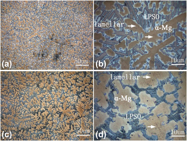
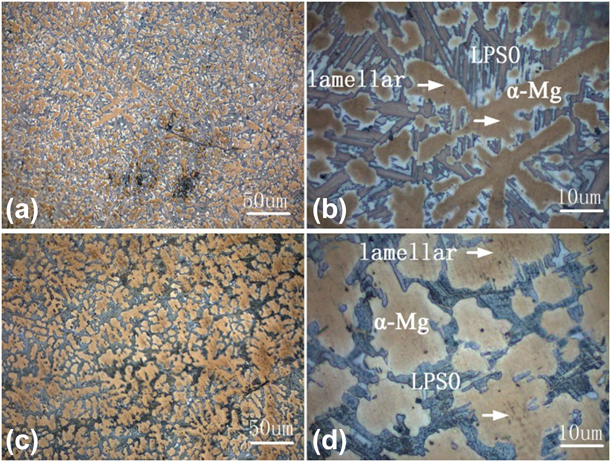
Figure 1 shows low-magnification and high-magnification optical microstructures of as-cast and solid-solution-treated alloys. The alloy is composed of α-Mg with eutectics and long-strip LPSO phase distributing at interdendritic regions in the as-cast condition as shown in Figs. 1(a) and 1(b). It is a clear observation that the alloy structure was uniform and no dendrites were found after solution treatment as shown in Figs. 1(c) and 1(d). The second phase is connected with α-Mg and forms the continuous network. The results show that the long-strip LPSO phases formed along grain boundary during solidification are not evolved in solid solution treatment. A kind of lamellar phase is precipitated in α-Mg matrix by white arrow as shown in Figs. 1(b) and 1(d). It is evident from Fig. 1 that two different shapes of LPSO phases are contained both in the as-cast and solid solution states of this alloy. One of the phases exists in the grain boundary, and the other is lamellar precipitated in the α-Mg matrix.
The microstructure of the alloy: (a and b) OM images of the as-cast specimen, (c and d) OM images of the solid-solution-treated specimen.
Figures 2(a) and 2(b) show the low- and high-magnification HAADF-STEM images of LPSO phases in as-cast Mg–Y–Ni–Zr alloy with the incident beam parallel to  ${\left[ {11\bar{2}0} \right]_\alpha }$ zone axis, respectively. Figure 2(b) is a high-magnification HAADF-STEM image, which displays the intergrowth of building blocks with different separation distances of Mg layers. The darker regions in Fig. 2(b) are Mg atomic layers due to the Z numbers of the Mg in Mg–Y–Ni–Zr alloy, which is the lowest. The atomic weights of Y(#39) and Ni(#28) atoms are higher than the Mg(#12) [Reference Itoi, Inazawa, Yamasaki, Kawamura and Hirohashi2]. The different Mg layers are shown with black arrows and represented by A, B, C, and D letters, respectively, in Fig. 2(b).
A HAADF-STEM image of LPSO phases in as-cast Mg–Y–Ni–Zr alloy. Incident beam direction is parallel to (a and b)  ${\left[ {11\bar{2}0} \right]_\alpha }$, (a) low and (b) high magnification, respectively.

Figure 3 displays a high-magnification HAADF-STEM image of LPSO structures of as-cast Mg–Y–Ni–Zr alloy with incident beam viewed along the  ${\left[ {11\bar{2}0} \right]_\alpha }$. Two types of LPSO phases were obtained as shown in Figs. 3(a) and 3(b). As shown in Figs. 3(a) and 3(b), the 18R- and 14H-LPSO structures coexist in the as-cast alloy. It also was found that 14H-and 18R-LPSO structures coexist in the cast Mg88Ni5Y7 alloy [Reference Jin, Fang and Mi18]. The results are consistent with the literatures that have been reported [Reference Jin, Fang and Mi18, Reference Jiang, Zhang, Bi, Li, Ren and Qin19]. Different LPSO structures could be distinguished by different separation distances between two building blocks. The 18R and 14H-LPSO structures are composed of two and three Mg layers, respectively. Figure 3(a) is a typical atomic-scale HAADF-STEM image of 18R-type LPSO phase viewed along the
 ${\left[ {11\bar{2}0} \right]_\alpha }$. The 18R LPSO phase has a fringe space of 1.59 nm (about 1.6 nm) between two build blocks and is composed of three building blocks and two Mg layers. The stacking sequence of 18R-LPSO is ABABABCACACABCBCBC along the [0001]Mg zone axis. The lattice parameter is derived as a LPSO = a Mg = 0.321 nm and c LPSO = 1/2n × c Mg [Reference Mi and Jin20]. The lattice parameter of 18R is a LPSO = a Mg = 0.321 nm and c LPSO = 1/2 × 18 × c Mg = 4.689 nm. It can be seen that the c-axis of 18R-type LPSO phase is 4.63 nm in Fig. 3(a), rather than the calculated c LPSO = 4.689 nm. Furthermore, the 14H-LPSO stacking sequence is ABABCACACACBAB along close-packed plane as shown in Fig. 3(b). The 14H-type LPSO structure is composed of two building blocks with three Mg layers. Its fringe space is 1.81 nm, and the c-axis distance is 3.71 nm as shown in Fig. 3(b), rather than the calculated c LPSO = 1/2 × 14 × c Mg = 3.647 nm. It is clear that both solute elements of Ni and/or Y are enriched in the stacking layers of ABCA, CABC, and BCAB, and the structure unit of ABCA-type layer stacking was indicted by a set of white lines from the HADDF-STEM image as shown in Figs. 3(a) and 3(b). The Y and Ni atoms are concentrated in the B and C layers [Reference Nie, Zhu and Morton21]. The stacking of three adjacent building blocks and the presence of α-Mg atomic layer between them could become an 18R structure [Reference Zhu, Morton and Nie22], as shown in Fig. 2(c). In summary, the LPSO phase structure is not formed with a simple polymorphic structure. Instead, the ordered structures are obtained which is attributed to solute elements enriched in four-atom layers next to the layered defect. It has been demonstrated that the LPSO structures show different numbers (two, three, four, and five) of Mg atomic layers between the building blocks in Mg–Y–Zn alloy annealed at 500 °C [Reference Kim, Ko, Sandlöbes, Heidelmann, Grabowski and Raabe23]. In this paper, the structures in Fig. 3(a) are composed of four building blocks with two and five Mg atomic layers. Furthermore, the LPSO structures are comprised of five building blocks with a separation distance of two and three Mg layers as shown in Fig. 3(b). In Fig. 3(d), the seven building blocks with different distances (two and four) of Mg atomic layers were shown. However, there are only a distance of two Mg atomic layers in Fig. 3(c). All structures can been referred to as “2 + 5” structure, “2 + 3” structure, and “2 + 4” structure in the as-cast alloy as shown in Fig. 3. These structures show different (two, three, four, and five) Mg atomic layers between the building blocks in the as-cast Mg–Y–Ni–Zr alloy. The “2 + 5” structure, “2 + 3” structure, and “2 + 4” structure represent 18R-, 18R-, and 14H-type LPSO phases, respectively.
Atomic HAADF-STEM images of LPSO polytypes of as-cast alloy showing the coexistence of (a) 18R and (b) 14H. The structures show four numbers (two, three, four, and five) of Mg atomic layes between the building blocks in (a)–(d). Incident beam// ${\left[ {11\bar{2}0} \right]_\alpha }$.

Figure 4 shows the atomic-resolution HAADF-STEM images of the LPSO structures in materials solution treated for 8 h at 773 K (500 °C). As shown Fig. 4(a), it is obviously seen that the lamellae have long-period order layers, and the α-Mg matrix only is 2H-type structure in low-magnification image [Reference Wu, Xu, Zheng, Peng, Zhang and Ding24]. Figure 4(b) is a high-magnification HAADF-STEM image obtained along the  ${\left[ {11\bar{2}0} \right]_\alpha }$ zone axis, which shows the intergrowth of different LPSO phases. The structures are comprised of different separation distances of Mg atomic layers between the bright fringe lines. Different separation distances in Fig. 4(b) can be represented as a, b, and c, respectively.
The HAADF-STEM images of LPSO phases in heat-treated Mg–Y–Ni–Zr alloy. Incident beam direction is parallel to (a and b)  ${\left[ {11\bar{2}0} \right]_\alpha }$, (a) low and (b) high magnification, respectively. Atomic HAADF-STEM images of LPSO polytypes of heat-treated alloy showing the coexistence of (c) 18R and (d) 14H. The structures show three numbers (two, three, and four) of Mg atomic layers between the building blocks in (b)–(d). Incident beam is parallel to
 ${\left[ {11\bar{2}0} \right]_\alpha }$.

The atomic-scale HAADF-STEM images of the bright fringe lines and different Mg layers can be observed in Figs. 4(c) and 4(d). The typical HAADF-STEM images of LPSO structures of the mixture of 18R- and 14H-LPSO structures are shown in the cast alloy after solution treated for 8 h at 773 K, as shown in Figs. 4(c) and 4(d). Therefore, LPSO phases of the 18R and 14H types are contained both in the as-cast and the solid solution alloys. This is because the alloy composition is different [Reference Jiang, Zhang, Bi, Li, Ren and Qin19]. The nominal composition of alloy is Mg–5Y–2.5Ni–0.5Zr (at.%) and the Ni/Y atomic ratio is 0.5 with lower Ni/Y atomic ratio. For the alloy with a higher Ni/Y atomic ratio, it was dissolved after heat treatment at 492 °C. The 14H-type LPSO phase can be stable up to a temperature exceed 550 °C [Reference Jiang, Zhang, Bi, Li, Ren and Qin19]. It can be indicated that substitution of Zn with Ni has the stable effect on 18R-type LPSO phase in Mg–Y–Zn alloy [Reference Zhu, Lapovok, Nie, Estrin and Mathaudhu10]. Liu et al. studied the morphology evolution of 18R structure during heat treatment in Mg–Y–Ni alloy, which was different from Mg–Y–Zn alloy [Reference Liu, Xue, Bai and Zhou25].
In Mg–Y–Ni alloy, the 18R-type structure was thermally stable and was not transformed into 14H-type structure at 773K. Liu et al. have reported that the thermal stability of 18R-type structure was improved by Ni substitution in Mg94Y4Zn2 [Reference Liu, Xue, Bai, Zhou and Liu26]. The replacement of Zn by Ni element improves the solid strengthening and inhibits transformation of 18R phases, resulting in improvement of strength and ductility of alloy. The 18R structures can transform 14H structures that have been reported [Reference Kim, Ko, Sandlöbes, Heidelmann, Grabowski and Raabe23], and the separation distance transforms from two to three Mg atomic layers in Mg–Y–Zn. However, the atomic scale images of two Mg layers converted to three Mg layers in the Mg–Y–Ni–Zr alloy were not found. The different numbers (two, three, and four) of Mg atomic layers between the building blocks were obtained in the LPSO phases. Two structures can only be referred to as “2 + 4” structure and “2 + 3” structure in the alloy for 8 h at 500 °C. It is seen clearly that the five Mg atomic layers is not found between the building blocks. Jin-Kyung Kim has reported the phase transformation in Mg–Y–Zn alloy [Reference Kim, Ko, Sandlöbes, Heidelmann, Grabowski and Raabe23] and the “2 + 4” structure changed to the “3 + 3” structure in sample annealed for 2.5 h at 500 °C. The separation distance (included two, three, four, and five Mg layers) can be changed by Shockley partial dislocation on the specific [Reference Kim, Ko, Sandlöbes, Heidelmann, Grabowski and Raabe23]. To the best of our knowledge, in this paper, the five Mg atomic layers possibly change to four or three Mg layers after heat treatment at 500 °C for 8 h. The separation distances can be formed by Mg atomic layers between the building blocks, i.e., two, three, and four. Only the 18R- and 14H-type LPSO phases can be shown, and no other structural LPSO phases appear.
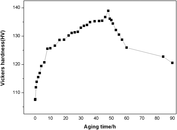
The hardness curve in Fig. 5 indicated that the alloy showed significant ageing-hardening response during artificial isothermal aging at 225 °C. The age hardening response was carried out from 0 h to 90 h for Mg–Y–Ni–Zr alloy. Before aging treatment, the sample was heat treated at 773 K for 8 h. The hardness is 107 HV for solution-treated alloy. At the beginning stage of aging, the hardness increases rapidly with the aging time before 10 h, then becomes slowly until obtaining a peak value. The aging hardness reaches up to the maximum value after 48 h. The maximum value is 138 HV at 48 h. The aged at 225 °C showed a considerably lower peak hardness after 48 h aging but the hardness subsequently reduced rapidly upon further aging. The value of the maximum value reduces to 124 HV when the alloy has been aged for 90 h. Aging time of 8, 48, and 90 h, which cover under-aged, peak-aged and over-aged conditions, respectively, were selected to investigate the peak-aged precipitation. The value of hardness is 138 HV at 48 h. The hardness of alloy is much higher than Mg–10 wt% Y binary alloy [Reference Xue, Ren, Luo, Zheng and Xu27]. Rare earth in Mg alloys plays an important role in precipitation strengthening. Many researchers indicted the aging hardness of Mg–Y at different times, and there are four stages of phase transform with increasing the aging time.
Hardness curve of the Mg–Y–Ni–Zr alloy after artificial aging at 225 °C.

They included the precipitation sequence of Mg–Y alloys were S.S.S.S.-β″(D019)-β′(cbco)-β(bcc). Apps et al. have studied three magnesium rare-earth alloys, containing Y, Gd, and Dy [Reference Apps, Karimzadeh, King and Lorimer14]. The composition of the phase is reflected in the mechanical properties that have been studied. Liu et al. reported the aging treatment for Mg–7Y–4Gd–1.5Zn–0.4Zr alloy [Reference Liu, Rokhlin, Elkin, Tang and Meng15]. After aging at 220 °C, the highest mechanical properties were obtained. The improvement of properties were attributed to the formation of β′, β″, and 14H LPSO phases. The process of precipitation of Mg-rare alloys, including aging treatments and TEM characterization, has been systematically studied by Nie et al. [Reference Nie and Muddle12]. As a matter a fact, the hardening effect of the aging process is mainly attributed to the formation of precipitates, especially the formation of a metastable β′ phase at the peak aging.
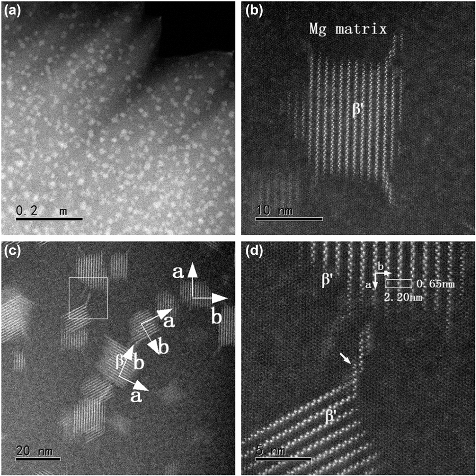
The HAADF-STEM images of the Mg–5Y–2.5Ni–0.5Zr (at.%) alloy aged at 225 °C for 48 h are shown in Fig. 6, taken with the incident beam parallel to the [0001]Mg direction. It can be seen in a low-magnification image that Y-rich precipitates as bright contrasts and the precipitates as white blocks as shown in Fig. 6(a). A high-magnification image of white block β′ precipitate with 20 nm sizes is characterized as shown in Fig. 6(b). Many studies have focused on studies β′ phase. Masahiko Nishijima et al. have studied characterization of β′ precipitate phase in Mg–2 at.% Y alloy aged to peak hardness by HAADF-STEM [Reference Nishijima, Yubuta and Hiraga17]. In Fig. 6(c), it can be seen that three different variants of β′ phases with different directions of a and b axes by two vertical arrows. This result is consistent with Mg–2Y alloy [Reference Nishijima, Yubuta and Hiraga17]. However, the β′ phases in Mg98Y2 alloy had been reported that thin crystals along the b-axis existed and result in superlattice reflections elongated [Reference Nishijima, Yubuta and Hiraga17]. The thin crystals along a-axis as shown in Fig. 6(c) and the superlattice reflections elongated exist along a-axis. As shown in Fig. 6(c), it can be clearly seen that each phase is not present alone but is connected by a structure formed by the relatively Y atoms. Figure 6(d) is the magnified image of the square area as shown in Fig. 6(c). The β′ phase precipitates in Mg–Y were remarkably different from in Mg–Gd alloy aged to a peak hardness condition. And an atomic arrangement of Mg7Y structure was showed [Reference Nishijima, Hiraga, Yamasaki and Kawamura16, Reference Nishijima, Yubuta and Hiraga17].
HAADF-STEM images of the Mg–5Y–2.5Ni–0.5Zr (at.%) alloy aged at 225 °C for 48 h, taken with the incident beam parallel to [0001]Mg direction. (a and b) show the low-magnification and high-magnification HAADF-STEM image of the β′ phases, respectively. (c) shows the axes of an orthorhombic structures of β′ phases by arrows. (d) shows the joints between precipitates by small arrow.

The structure of a unit cell in white rectangle is displayed in Fig. 6(d). The zigzag arrays of Y atoms with an interval of b/2 = 1.11 nm and the white dots represent the Y atoms. Nine Y atoms form the basic atomic arrangement of β′ phase, as shown in Fig. 6(d) by white rectangle. The lattice parameters of a unit cell are slightly different a = 2a 0 = 0.64 nm,  $b = 4\sqrt 3$a 0 = 2.28 nm, and c = c 0 = 0.52 nm. The lattice parameters of a and b axes for β′ phases are a = 0.65 nm, b = 2.20 nm, and c = 0.52 nm as shown in Fig. 6(d). It can be clearly seen that there are linear zigzag Y atoms and hexagonal arrangements of bright dots along the a-axis direction. A new atomic junction stack is formed between precipitates, and the morphology consists of one zigzag Y atoms projection and three hexagon Y atoms projections, as shown by arrow in Fig. 6(d).
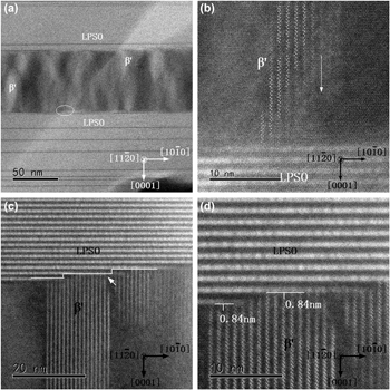
Figure 7(a) shows the HAADF-STEM image of the LPSO structures interact with β′ phase under-aging condition at 225 °C in the Mg–Y–Ni–Zr alloy. The LPSO phases were obtained during melting process, which could not be dissolved after solid solution treatment at 573 K for 8 h, whereas the β′ phases gradually grow during the aging process. The LPSO phases cannot be characterized, taken with the incident beam parallel to [0001]Mg direction. The interaction between the LPSO and β′ phases was characterized along the  ${\left[ {11\bar{2}0} \right]_{{\rm{Mg}}}}$ direction as shown in Fig. 7(a).
The HAADF-STEM images in the Mg–Y–Ni–Zr samples aged treatment showing: (a and b) the LPSO structures interact with β′ phase under-aging condition; (c and d) the LPSO structures intercalated with β′ phase peak-aging condition. Incident beam// ${\left[ {11\bar{2}0} \right]_{{\rm{Mg}}}}$.

It can be seen that the precipitation phases embed in the matrix between LPSO slices, and the sandwich structures were obtained. The optimized mechanical properties with excellent strength and high ductility in Mg alloy have been proposed [Reference Li, Zhu, Qiu, Yin, Rong and Zhang28]. This is because that the coarsening of predominant strengthening β′ phases was effectively obstructed and the dislocations were gathered at interfaces in the sandwich structure [Reference Li, Zhu, Qiu, Yin, Rong and Zhang28]. The β′ phases play the significant role in strengthening Mg alloys via dislocations cutting nanoscale phases or Orowan strengthening mechanism [Reference Nishijima, Hiraga, Yamasaki and Kawamura16]. However, the alloys with good ductility are attributed to have the pinning effect on grain growth and inhibit grain boundary movement [Reference Li, Zhu, Qiu, Yin, Rong and Zhang28]. Therefore, the sandwich structures observed in Mg alloys by HAADF-STEM are indispensable. With aging times increased, the coarsening of β′ phases is inhibited by the LPSO structures. Zheng et al. have vividly reported the schematic diagram between the β′ and the LPSO phases in Mg-Gd-Y-Zn-Zr alloy. The β′/LPSO interfaces are characterized and there are three types in Mg–Gd–Y–Zn–Zr alloy aged at 225 °C for 48 h [Reference Zheng and Chen29].
In Mg–Y–Ni–Zr alloy, the interactions between the LPSO phase and the β′ phases will be more clearly explored from different aging times. The atomic-scale β′ phases are presented at under-aging condition along the  ${\left[ {11\bar{2}0} \right]_{{\rm{Mg}}}}$ direction. It can be seen that the stepped β′ precipitates form in supersaturated Mg matrix under-aged condition as shown in Fig. 7(b). There are stepped precipitates represented for β′ phases appearing along the
 ${\left[ {10\bar{1}0} \right]_{{\rm{Mg}}}}$ direction, indicating that in supersaturated Mg matrix, the Y atoms are not completely precipitated at early aged treatment.
With the aging treatment progresses, the Y atoms gradually precipitate in the Mg matrix, and the β′ phases gradually grow. The size of the β′ phases ranged from 10 to 25 nm at peak-aged condition in the Mg–Y–Ni–Zr alloy, as shown in Fig. 7(c). Comparing Figs. 7(b) and 7(c), it is found that the β′ phases gradually evolve along the [0001]Mg direction, and the stepped precipitates disappear. It is also clearly seen that there are the LPSO phases associated with two growth ledges as shown in Fig. 7(c). The growth ledges are consistent with the Shockley partial dislocation [Reference Zhu, Morton and Nie30]. When the β′ phases encounter the LPSO blocks, its growth is inhibited in the [0001]Mg direction. Before the growth ledges are encountered, the β′ phases continue to grow. It can also be seen that the β′ phases become longer along the growth direction  $\left( {{{\left[ {10\bar{1}0} \right]}_{{\rm{Mg}}}}} \right)$ of the growth ledges and correspondingly two growth ledges with the β′ phases are formed, as shown in Fig. 7(c). The β′ phases are intercepted by the building block from [0001]Mg direction. The interfaces between β′ and LPSO phases are presented a high-magnification HAADF-STEM as shown in Fig. 7(d). Seen from Fig. 7(d), there is a straight gaps width of about ∼0.84 nm between β′ and LPSO phases, indicated by the solid white lines. In this gap, it is relatively low contrast. It means that heavy atoms are absent, such as Y, Ni elements. and the gaps consist of Mg atomic layers. In Figs. 7(b) and 7(c), the heterogenous nucleation sites of the β′ phases are presented in Mg matrix between the LPSO phases and gradually grow along the [0001]Mg direction. It can be seen from Fig. 7(d) that the gaps exist; therefore, the LPSO cannot be considered as the heterogenous nucleation sites. The interface between the LPSO and β′ phases and the areas are not changed due to the gaps formed Mg layers.
Conclusion
The microstructure of a Mg–5Y–2.5Ni–0.5Zr (at.%) alloy has been investigated by the OM and HAADF-STEM in this paper. The following results can be drawn:
(1) It was found that the block and lamellar LPSO phases coexist in as-cast and in solid solution conditions Mg–5Y–2.5Ni–0.5Zr (at.%) alloy. The analysis revealed that 18R-type and 14H-type remained thermally stable after heat treatment at 500 °C for 8 h. The block and lamellar LPSO phases coexist in as-cast and in solid solution conditions Mg–5Y–2.5Ni–0.5Zr (at.%) alloy. The analysis revealed that 18R layers, i.e., two, three, and four after heat treatment at 500 °C. Only the 18R and 14H are shown, no other structural LPSO phases appear.
(2) The improvement of the hardness is mainly ascribed to the presence of the β′ phases during isothermal aging at 225 °C in Mg–5Y–2.5Ni–0.5Zr (at.%) alloy. This alloy shows the highest hardness at peak-aged condition due to the existence of the many β′ phases with 20 nm size and uniform distribution in Mg matrix. The lattice parameters of a and b axes for β′ phases are a = 0.65 nm, b = 2.20 nm, and c = 0.52 nm by HAADF-STEM. The morphology consists of one zigzag Y atoms projection and three hexagon Y atoms projections along the a-axis direction at joint between precipitates.
(3) The LPSO phases do not dissolve during the aging in Mg–5Y–2.5Ni–0.5Zr (at.%) alloy. The interactions between the LPSO and β′ phases are divided into two parts: At the under-aging condition, Y atoms are not completely precipitated and the β′ phases do not fully grow, forming a step in the sandwich along the
 ${\left[ {10\bar{1}0} \right]_{{\rm{Mg}}}}$ direction. During the peak-aging condition, the β′ phases grow along the [0001]Mg direction and are hindered when encountering building blocks, thereby suppressing the coarsening of β′ phases and forming the gaps of a width about ∼0.84 nm. It also can be concluded from two stages that β′ phases nucleation is formed in the middle of the sandwich structures and the final stepped β′ phases are characterized along the ${\left[ {10\bar{1}0} \right]_{{\rm{Mg}}}}$ direction.


Experimental procedures
In order to get the material for research, high pure Mg (99.99%), high pure Ni(99.99%), and Mg–25 wt% Y, Mg–30 wt% Zr master alloy were prepared by using the electric resistance furnace in a 99% CO2 and 1% SF6 protective atmosphere. The nominal composition of alloy was Mg–5Y–2.5Ni–0.5Zr (at.%). High pure magnesium was added at 720 °C and added the master alloy and high pure Ni(99.99%) at 760 °C, then the all metals were melted completely, stirred for approximately 300 s, and hold for 30 min at 730 °C. The melting were absolutely poured into the preheat 200 °C mold. The cast alloys were heat treatment at 500 °C for 8 h, followed by water quenching at room temperature. These treated alloys were aged at 225 °C for 90 h in salt bath. Hardness was obtained from the aged specimen by using a Vickers hardness tester with a load of 49N and a holding time of 15 s, and eight measurements were collected for different aging times. The sample was mechanically polished and etched by acetic picral for metallographic observation. The foils were obtained by punching 3 mm diameter discs, then using the 25% nitric acid and 75% methanol by electrolytic polishing at −30 °C with a voltage of 20 V. To remove the oxide film during polishing, the foils were prepared by low-angle ion milling using a Ganta Precision Ion Polishing System (PIPS) at 5 keV with an angle of 4° about 30 min. Atomic-resolution HAADF-STEM was performed with JEM-ARM200F (JEOL Co., Ltd., Tokyo, Japan), equipped with a probe-Cs corrector, and operated at 200 kV.
Acknowledgments
This work is supported by National Key Research and Development Plan (Grant No. 2016YFB0701201).