1.0 INTRODUCTION
Quadcopter designs have become popular in Unmanned Aerial Vehicle (UAV) research. UAVs are used in military and civil scopes, focusing on tasks such as searching, rescue, vigilance, inspection, and so on. These vehicles are under actuated mechanical systems, which complicates the control design stage. Techniques developed for fully actuated robots cannot be directly applied to the under actuated non-linear mechanical systems(Reference Fantoni and Lozano1). Therefore, non-linear modelling techniques and modern non-linear control theory are usually employed to achieve autonomous flight with high performance(Reference Castillo, Lozano and Dzul2).
Many efforts have been made to control the quadrotor helicopter and many strategies have been developed in order to solve the path tracking problem for this type of system(Reference Raffo, Ortega and Rubio3–Reference Kim, Kang and Park7). In Ref. Reference Mistler, Benallegue and M'Sirdi8, a non-linear model was proposed, presenting the helicopter kinematics and dynamics based on Newton-Euler formalism.
The aerodynamic forces and moments acting on this model were considered. The path tracking problem and state observation were solved using exact linearisation techniques(Reference Mokhtari, Benallegue and Orlov9) and non-interacting control via dynamic feedback. In Ref. Reference Bouabdallah, Murrieri and Siegwart10, the same methodology was used to obtain its motion equations, but considering also the rotor dynamics. The system equations were written in state space for the controller design. In Ref. Reference Ortega, Vargas, Vivas and Rubio11, a strategy to control mechanical systems considering the tracking error dynamic equation was proposed. In such strategies, a non-linear H∞ control, formulated via game theory, was applied. This strategy provides, by an analytical solution, a constant gain similar to the results obtained with the feedback linearisation procedures. In Ref. Reference Castillo, Dzul and Lozano12, a nested saturations control to move a quadrotor to a position and stabilise its attitude has been proposed. In Refs Reference Altug, Ostrowski and Mahony13 and Reference Altug, Ostrowski and Taylor14, Altug et al. used the back-stepping method to stabilise a quadrotor by keeping the positions and the yaw angle constant and the pitch and the roll angle zero. In Ref. Reference Tayebi and Mcgilvray15, Tayebi et al. proposed a controller based on the compensation of the Coriolis and gyroscopic torques to stabilise the attitude of a quadrotor as it vertically takes off and lands. Bouabdallah et al. mechanically designed, dynamically modelled and used non-linear control techniques in their works(Reference Bouabdallah and Siegwart16,Reference Bouabdallah, Murrieri and Siegwart17) . Beji et al.(Reference Beji, Abichou and Zemalache18) presented structure and control of a quadrotor where two rotors are bidirectional. In Ref. Reference Shafiqul, Xiaoping and Abdulmotaleb19, an adaptive sliding mode control for quadrotor has been presented. Romero et al.(Reference Romero, Benosman and Lozano20) used a simple vision system for a quadrotor's local positioning and orientation in indoor flight. Castillo et al.(Reference Castillo, Lozano and Dzul21–Reference Castillo, Dzul and Lozano23) used a Lagrangian model of the quadrotor and the control is based on Lyapunov analysis.
Back-stepping is a technique developed for designing a stabilising controller for a certain class of non-linear systems. It has a recursive structure, in which the existing states of the first-order model are recursively used to stabilise the steady motion of the second-order model. With the back-stepping techniques, we are able to elegantly reject strong disturbances, but stabilisation in hover flight was delicate. Another improvement is now introduced thanks to Integral Back-Stepping (IBS). The idea of using integral action in the back-stepping design was first proposed in Ref. Reference Kanellakopoulos and Krein50 and applied in Ref. Reference Tan, Chang, He and Tan51. In fact, back-stepping is well suited for the cascaded structure of the quadrotor dynamics. Moreover, the controller design process can be straightforward if done properly. In addition, this method guarantees asymptotic stability and has robustness to some uncertainties, while the integral action cancels the steady state errors.
The back-stepping controller is popular for its path tracking abilities, stability and speed. However, in cases of undeterminable disturbances caused by natural and synthetic external unrespectable forces such as wind, loads and inertia calculation error, the back-stepping controller abilities starts to fail as a cause of its high dependency upon the physical model. As a result, we need a hand, a compensation from a more independent controller, which is in this case the Fuzzy Logic Compensator.
Fuzzy logic(Reference Zadeh24–Reference Passino and Yurkovich26) is a mathematical method that can be utilised to transform an inexact knowledge into the form of a computer algorithm. The first fuzzy control application belongs to Mamdani and Assilian(Reference Mamdani and Assilian27). The fuzzy control applications in several domains begin with electrical household industry and consumer electronics up to other industries like mechanical and robotic systems, power plants and systems, telecommunications, transportation systems, automotive systems, chemical processes and nuclear reactors(Reference Precup and Hellendoom28–Reference ROSS33). The control approach based on human experience is acting in fuzzy controllers by expressing the control requirements and elaborating the control signal in terms of the natural If-Then rules(Reference Mamdani34,Reference Harkouss, Accouch and Issa35) .
Fuzzy Logic Controllers (FLCs) are successfully applied to control quadrotor. In Ref. Reference Raza, Gueaieb and Casolo36, a Mamdani type of fuzzy inference is used to control quadrotor, and in Ref. Reference Santos, Lopez and Morata37 the comparison of Mamdani and Takagi-Sugeno-Kang (TSK) fuzzy controllers is conducted. In this paper, fuzzy logic was utilised for building up compensator of uncertainties. The proposed compensator corrects corresponding compensatory force and moment commands provided by the dynamic controller, on the base of trajectory tracking errors.
In this paper, a non-linear model for the quadrotor has been developed to simulate the dynamics of the Quadrotor. This model is based on several bibliographical studies, as presented in Refs Reference Pounds, Mahony and Corke4–Reference Kim, Kang and Park7, Reference Castillo, Lozano and Dzul21–Reference Castillo, Dzul and Lozano23, and Reference Miller38–Reference Leishman45, and takes into consideration most of the non-linearities characterising its motion in order to have a simulator as close as possible to the real Quadrotor. In fact, we have identified the coefficients of this model using experimental data presented in references(Reference Shamaa46,Reference Saied, Shamaa, Shraim, Francis, Lussier and Fantoni47) . After identifying the coefficients of the model, we have used it to develop the IBS controller in order to ensure that it will track a desired path. The presence of a complex trajectories and unknown disturbances motivated us to propose a fuzzy compensator in parallel with the IBS controller.
2.0 MODEL
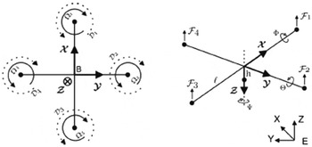
A quadrotor is a helicopter with four rotors. Rotor speeds are controlled to produce the desired lift force. It is an under-actuated system, dynamic vehicle with four input forces and six outputs. Basic motions of a quadrotor can be described as follows. Vertical motion can be achieved by increasing or decreasing the speed of the four rotors. Motion along the x axis and y axis can be obtained through a differential control strategy of the lift force by each rotor. In order to avoid the yaw drift due to the reactive torques, the quadrotor aircraft is configured such that one set of rotors (rotors 1 and 3) rotate clockwise and the other set of rotors (rotors 2 and 4) rotate counter-clockwise. There is no change in the direction of rotation of the all rotors. The yaw motion can be obtained by increasing the speed of one set of rotors and decreasing the speed of other set of rotors. Adding to that, the fact that the total lift force is maintaining unchanged in order to avoid the up-down motion(Reference Fang, Zhi, Jun and Jian48). Let us consider earth-fixed frame E and a body-fixed frame B as shown in the Fig. 1.
Quadrotor coordinate system.

From the classical control theory, the rotation matrix from frame B to frame E is given by:
 $$\begin{equation}
R = \left( {\begin{array}{@{}*{3}{c}@{}} {c\theta .c\psi }&\quad {s\varphi .s\theta .c\psi - s\psi .c\varphi }&\quad{s\psi .s\varphi + s\theta .c\psi .c\varphi }\\ {c\theta .s\psi }&\quad {c\theta .c\psi + s\theta .s\varphi .s\psi }&\quad {s\theta .s\varphi .c\psi - c\psi .s\varphi }\\ { - s\theta }&\quad {c\theta .s\varphi }&\quad {c\varphi .c\theta } \end{array}} \right),
\end{equation}$$
where c(.) = cos(.) and s(.) = sin(.). φ is the angular rotation about X axis or roll angle, .θ. is the angular rotation about the Y axis or pitch angle, and ψ is the angular rotation about Z axis or yaw angle (Fig. 1).
2.1 Aerodynamic forces and moments
The aerodynamic forces and moments are derived using a combination of momentum and blade element theory. For an easier reading of the equations below, we recall some symbols: σ solidity ratio, a lift slope, μ advance ratio, λ inflow ratio,
 $\upsilon $
induced velocity, ρ air density, R
rad rotor radius, l distance propeller axis-COG (Centre Of Gravity), θ0 pitch of incidence, θtw twist pitch,
 ${\bar{C}_d}$
drag coefficient at 70% radial station.
Ω i is the angular rotation of the blade element. The Thrust force Ti is the resultant of the vertical forces acting on all the blade elements ‘i’:
 $$\begin{equation}
\left\{ \begin{array}{@{}l@{}} {T_i} = {C_T}\rho A{({\Omega _i}{R_{{\rm{rad}}}})^2}\\[8pt] \frac{{{C_T}}}{{\sigma a}} = \left( {\frac{1}{6} + \frac{1}{4}{\mu ^2}} \right){\theta _0} - \left( {1 + {\mu ^2}} \right)\frac{{{\theta _{tw}}}}{8} - \frac{1}{4}\lambda \end{array} \right.
\end{equation}$$
Hub force Η ι is the resultant of the horizontal forces acting on all the blade elements ‘i’:
 $$\begin{equation}
\left\{ \begin{array}{@{}l@{}} {H_i} = {C_H}\rho A{({\Omega _i}{R_{{\rm{rad}}}})^2}\\[8pt] \frac{{{C_H}}}{{\sigma a}} = \frac{1}{{4a}}\mu {{\bar{C}}_d} + \frac{1}{4}\lambda \mu \left( {{\theta _0} - \frac{{{\theta _{tw}}}}{2}} \right) \end{array} \right.
\end{equation}$$
Drag moment Qi is caused by the aerodynamic forces acting on the blade elements ‘i’. It determines the power required to spin the rotor:
 $$\begin{equation}
\left\{ \begin{array}{@{}l@{}} {Q_i} = {C_Q}\rho A{({\Omega _i}{R_{{\rm{rad}}}})^2}{R_{{\rm{rad}}}}\\[8pt] \frac{{{C_Q}}}{{\sigma a}} = \frac{1}{{8a}}\left( {1 + {\mu ^2}} \right){{\bar{C}}_d} + \lambda \left( {\frac{1}{6}{\theta _0} - \frac{{{\theta _{{\rm{tw}}}}}}{8} - \frac{1}{4}\lambda } \right) \end{array} \right.
\end{equation}$$
Rolling moment Rm i is the integration over the entire rotor of the lift of each section acting at a given radius (not to be confused with the overall rolling moment):
 $$\begin{equation}
\left\{ \begin{array}{@{}l@{}} {R_m}_i = {C_{{R_m}}}\rho A{({\Omega _i}{R_{{\rm{rad}}}})^2}{R_{{\rm{rad}}}}\\[8pt] \frac{{{C_{{R_m}}}}}{{\sigma a}} = - \mu \left( {\frac{1}{6}{\theta _0} - \frac{{{\theta _{{\rm{tw}}}}}}{8} - \frac{1}{8}\lambda } \right) \end{array} \right.
\end{equation}$$
Ground effect is related to a reduction of the induced airflow velocity. The principal need is to find a model of this effect for quadrotor to improve the autonomous take-off and landing controllers. A simple way to proceed is to consider that the inflow ratio In Ground Effect (IGE) as:
 ${\lambda _{{\rm{IGE}}}} = ({\upsilon _{i,{\rm{OGE}}}} - \delta {\upsilon _i} - \dot{z})/{\Omega _i}{R_{{\rm{rad}}}}$
, where the variation of the induced velocity is
 $\delta {\upsilon _i} = {\upsilon _i}/{(4z/{R_{{\rm{rad}}}})^2}$
.
We can then rewrite the thrust coefficient IGE as follows:
 $$\begin{equation}
\left\{ \begin{array}{@{}l@{}} {T_{{\rm{IGE}}}} = C_T^{{\rm{IGE}}}\rho A{({\Omega _i}{R_{{\rm{rad}}}})^2}\\[8pt] \frac{{C_T^{{\rm{IGE}}}}}{{\sigma a}} = \frac{{C_T^{{\rm{OGE}}}}}{{\sigma a}} + \frac{{\delta {\upsilon _i}}}{{4\Omega {R_{{\rm{rad}}}}}} \end{array} \right.
\end{equation}$$
2.2 General moments and forces
Quadrotor motion is obviously caused by a series of forces and moments coming from different physical effects. In this section, moments and forces are presented. J is the inertia matrix of the quadrotor used in the model:
 $$\begin{equation*}
J = \left( {\begin{array}{@{}*{3}{c}@{}} {{I_{xx}}}&\quad 0&\quad 0\\ 0&\quad {{I_{yy}}}&\quad 0\\ 0&\quad 0&\quad {{I_{zz}}} \end{array}} \right)
\end{equation*}$$
Ixx, Iyy, Izz are the moments of inertia about X, Y, Z axis, respectively.
The rolling moments have the following components:
-
1. Body gyro effect:
 $$\begin{equation*}\dot{\theta }\dot{\psi }({I_{yy}} - {I_{zz}})\end{equation*}$$
-
2. Rolling moment due to forward flight:
$$\begin{equation*}{( - 1)^{i + 1}}\sum\limits_{i = 1}^4 {} {R_{mxi}}\end{equation*}$$
-
3. Propeller gyro effect:
$$\begin{equation*}{J_{TP}}\dot{\theta }{\Omega _r}\end{equation*}$$
-
4. Hub moment due to sideward flight:
$$\begin{equation*}h\left( {\sum\limits_{i = 1}^4 {{H_{yi}}} } \right)\end{equation*}$$
-
5. Roll actuators action:
$$\begin{equation*}l( - {T_2} + {T_4})\end{equation*}$$


The pitching moments are as following:
-
1. Body gyro effect:
$$\begin{equation*}\dot{\theta }\dot{\psi }({I_{zz}} - {I_{xx}})\end{equation*}$$
-
2. Rolling moment due to forward flight:
$$\begin{equation*}h\left( {\sum\limits_{i = 1}^4 {{H_{xi}}} } \right)\end{equation*}$$
-
3. Propeller gyro effect:
$$\begin{equation*}{J_{TP}}\dot{\varphi }{\Omega _r}\end{equation*}$$
-
4. Hub moment due to sideward flight:
$$\begin{equation*}{( - 1)^{i + 1}}\sum\limits_{i = 1}^4 {} {R_{myi}}\end{equation*}$$
-
5. Roll actuators action:
$$\begin{equation*}l({T_1} - {T_3})\end{equation*}$$


The yawing moments are described as follows:
-
1. Body gyro effect:
$$\begin{equation*}\dot{\theta }\dot{\varphi }({I_{xx}} - {I_{yy}})\end{equation*}$$
-
2. Hub force unbalance in forward flight:
$$\begin{equation*}l({H_{x2}} - {H_{x4}})\end{equation*}$$
-
3. Inertial counter-torque:
$$\begin{equation*}{J_{TP}}{\dot{\Omega }_r}\end{equation*}$$
-
4. Hub force unbalance in sideward flight:
$$\begin{equation*}l( - {H_{y1}} + {H_{y3}})\end{equation*}$$
-
5. Counter-torque unbalance:
$$\begin{equation*}{( - 1)^i}\sum\limits_{i = 1}^4 {{Q_i}} \end{equation*}$$


2.3 Equations of motion
The equations of motion are derived from the forces and moments listed above. After some simplifications, we obtain the quadrotor model in the state space form:
 $$\begin{equation}
\dot{X} = f(X,U),
\end{equation}$$
 $$\begin{equation*}
f(X,U) = \left( {\begin{array}{@{}*{1}{c}@{}} {\dot{\varphi }}\\ {\dot{\theta }\dot{\psi }{a_1} - \dot{\theta }{a_2}{\Omega _r} + {b_1}{U_2}}\\ {\dot{\theta }}\\ {\dot{\varphi }\dot{\psi }{a_3} + \dot{\varphi }{a_4}{\Omega _r} + {b_2}{U_3}}\\ {\dot{\psi }}\\ {\dot{\theta }\dot{\varphi }{a_5} + {b_3}{U_4}}\\ {\dot{z}}\\ { - g + (c\varphi .c\theta )\frac{1}{m}{U_1}}\\ {\dot{x}}\\ {{u_x}\frac{1}{m}{U_1}}\\ {\dot{y}}\\ {{u_y}\frac{1}{m}{U_1}} \end{array}} \right)
\end{equation*}$$
X is the state vector as follows:
 $$\begin{equation*}
X = [ {\begin{array}{*{20}{c}} \varphi &\quad {\dot{\varphi }}&\quad \theta &\quad {\dot{\theta }}&\quad \psi &\quad {\dot{\psi }}&\quad z&\quad {\dot{z}}&\quad x&\quad {\dot{x}}&\quad y&\quad {\dot{y}} \end{array}} ]
\end{equation*}$$
and
 $$\begin{equation*}
{a_1} = ({I_{yy}} - {I_{zz}})/{I_{xx}},{a_2} = {J_{TP}}/{I_{xx}}, {a_3} = ({I_{zz}} - {I_{xx}})/{I_{yy}}, {a_4} = {J_{TP}}/{I_{yy}}, {a_5} = ({I_{xx}} - {I_{yy}})/{I_{zz}}\end{equation*}$$
 ${J_{T\hspace*{-.6pt}P}}$
is the rotor total inertia with respect to the rotor main axis.
And
 $$\begin{equation*}
{b_1} = l/{I_{xx}},{b_2} = l/{I_{yy}},{b_3} = 1/{I_{zz}}
\end{equation*}$$
 $$\begin{equation*}
{\Omega _r} = {\Omega _1} - {\Omega _2} + {\Omega _3} - {\Omega _4}
\end{equation*}$$
 $$\begin{equation*}
\left\{ \begin{array}{@{}l@{}} {u_x} = s\psi .s\varphi + s\theta .c\psi .c\varphi \\ {u_y} = s\theta .c\varphi .s\psi - c\psi .s\varphi \end{array} \right.
\end{equation*}$$
The vector
 $U = {[ {\begin{array}{*{20}{c}} {{U_1}}&{{U_2}}&{{U_3}}&{{U_4}} \end{array}} ]^T}$
is the control vector inputs of the model and is composed of:
-
1. The vertical thrust U 1 that allows us to control the height z:
$$\begin{equation*}{U_1} = b(\Omega _1^2 + \Omega _2^2 + \Omega _3^2 + \Omega _4^2)\end{equation*}$$
-
2. The virtual torque U 2 around the x axis to control the roll angle:
$$\begin{equation*}{U_2} = bl( - \Omega _2^2 + \Omega _4^2)\end{equation*}$$
-
3. The virtual torque U 3 around the y axis to control the pitch angle:
$$\begin{equation*}{U_3} = bl(\Omega _1^2 - \Omega _3^2)\end{equation*}$$
-
4. The virtual torque U 4 around the z-axis to control the yaw angle ψ:
$$\begin{equation*}{U_4} = d( - \Omega _1^2 + \Omega _2^2 - \Omega _3^2 + \Omega _4^2)\end{equation*}$$


b is the thrust coefficient, and d is the drag coefficient. The differential equations of the quadrotor are implemented in Simulink/Matlab, and this model is validated by different strategies and the following numerical values have been used to run the program: m = 1 kg, l = 0.235 m, Ixx = 0.0081 N.m/rad/s2 , Iyy = 0.0081 N.m/rad/s 2, Izz = 0.0142 N.m/rad/s2 , JTP = 104 × 10−6 N.m/rad/s2, b = 54.2 × 10⁻⁶ N.m/rad/s, and d = 1.1 × 10⁻⁶ N.m/rad/s.
3.0 INTEGRAL BACK-STEPPING CONTROLLER DESIGN
Several controllers have been tested and compared in order to stabilise the quadrotor, including the: PID, state feedback, back-stepping, feedback linearisation, the H∞, sliding modes, fuzzy logic, IBS and other controllers, and a comparison among several controllers has been done(Reference Krayem49). In this section, we use the IBS controller to stabilise our quadrotor.
3.1 Attitude (angular motions) control
Attitude control is the heart of the control block; it keeps the 3D orientation of the helicopter to the desired value. The first step in IBS control design is to consider the tracking error e
1 = φ
d
− φ and its dynamics
 ${\dot{e}_1} = {\dot{\varphi }_d} - {\omega _x}$
.
The angular speed ω x is not our control input and has its own dynamics, so we set for it a desired behaviour and consider it as our virtual control:
 $$\begin{equation}
{\omega _{xd}} = {c_1}{e_1} + {\dot{\varphi }_d} + {\lambda _1}\int\limits_0^t {{e_1}(\tau )d\tau }
\end{equation}$$
We can see that the integral term is now introduced to the virtual control term.
We compute the error e 2 of ω x and it dynamics as follows:
 $$\begin{equation}
{\dot{e}_2} = {c_1}({\dot{\varphi }_d} - {\omega _x}) + {\ddot{\varphi }_d} + {\lambda _1}{e_1} - \ddot{\varphi }
\end{equation}$$
We can rewrite roll tracking error dynamics as:
 $$\begin{equation}
{\dot{e}_1} = - {c_1}{e_1} - {\lambda _1}\int\limits_0^t {{e_1}(\tau )d\tau } + {e_2},
\end{equation}$$
where e 2 = ω xd − ω x
By replacing
 $\ddot{\varphi }$
by its corresponding expression from the system differential equation, the control input U
2 appears as:
 $$\begin{equation}
{\dot{e}_2} = {c_1}({\dot{\varphi }_d} - {\omega _x}) + {\ddot{\varphi }_d} + {\lambda _1}{e_1} - \dot{\theta }\dot{\psi }{a_1} + \dot{\theta }{a_2}{\Omega _r} - {b_1}{U_2}
\end{equation}$$
By combining, from the equations treated above, the tracking errors of the position e
1, of the angular speed e
2 and of the integral position tracking error
 $\int\limits_0^t {{e_1}(\tau )d\tau } $
, one obtains:
 $$\begin{equation}
{\dot{e}_2} = {c_1}\left( { - {c_1}{e_1} - {\lambda _1}\int\limits_0^t {{e_1}(\tau )d\tau } + {e_2}} \right) + {\ddot{\varphi }_d} + {\lambda _1}{e_1} - {\tau _x}/{I_{xx}},
\end{equation}$$
where τ x is the overall rolling torque.
The desirable dynamics for the angular speed tracking error to ensure stability is:
 $$\begin{equation}
{\dot{e}_2} = - {c_2}{e_2} - {e_1}
\end{equation}$$
Note that the stability can be proved by choosing a Lyapunov candidate function as follows(Reference Bouabdallah and Siegwart16):
 $$\begin{equation}
V = \frac{1}{2}{\lambda _1}X_1^2 + \frac{1}{2}e_1^2 + \frac{1}{2}e_2^2
\end{equation}$$
 $X_1^{} = \int\limits_0^t {{e_1}(\tau )d\tau } $
and λ1 is a positive constant.
Deriving the Lyapunov Candidate and by using Equations (10) and (13), we get:
 $$\begin{equation}
\dot{V} = - {c_1}e_1^2 - {c_2}e_2^2 \le 0
\end{equation}$$
This global stability can be obtained if we choose the control input U 2 as:
 $$\begin{equation}
{U_2} = [(1 - c_1^2 + {\lambda _1}){e_1} + ({c_1} + {c_2}){e_2}]/{b_1} + \left[ - {c_1}{\lambda _1}\int\limits_0^t {{e_1}(\tau )d\tau } + {\ddot{\varphi }_d} - \dot{\theta }\dot{\psi }{a_1} - \dot{\theta }{a_2}{\Omega _r}\right]/{b_1}
\end{equation}$$
c 1, c 2 and λ1 are positive constants that forms the control parameters which determines the convergence speed of the angular speed loop.
Similarly, the pitch controller is:
 $$\begin{eqnarray}
{U_3} = \big[(1 - c_3^2 + {\lambda _2}){e_3} + ({c_3} + {c_4}){e_4}\big]/{b_2}\left[ - {c_3}{\lambda _2}\int\limits_0^t {{e_2}(\tau )d\tau } + {\ddot{\theta }_d} - \dot{\varphi }\dot{\psi }{a_3} + \dot{\varphi }{a_4}{\Omega _r}\right]/{b_2},\nonumber\\
\end{eqnarray}$$
and the yaw controller is:
 $$\begin{equation}
{U_4} = \big[(1 - c_5^2 + {\lambda _3}){e_5} + ({c_5} + {c_6}){e_6}\big]/{b_3} - \left[{c_5}{\lambda _3}\int\limits_0^t {{e_3}(\tau )d\tau } \right]/{b_3},
\end{equation}$$
where (c 3, c 4, c 5, c 6, λ2, λ3) > 0 are the control parameters, where:
 $$\begin{equation*}
\left\{ \begin{array}{@{}l@{}} {c_1} = {c_3} = 10\\ {c_2} = {c_4} = {c_5} = {c_6} = 2\\ {\lambda _1} = {\lambda _2} = 1000\\ {\lambda _3} = 0.01 \end{array} \right.
\end{equation*}$$
3.2 Altitude control
On the control law side, the altitude tracking error is defined as: e 7 = zd − z
The speed tracking error is:
 $$\begin{equation}
{e_8} = {c_7}{e_7} + {\dot{z}_d} + {\lambda _4}{X_4} - \dot{z},
\end{equation}$$
where X 4 = ∫ t 0 e 5(τ)dτ. The control law that ensures global stability of attitude tracking is then:
 $$\begin{equation}
{U_1} = m\left[ {\frac{{g + (1 - c_7^2 + {\lambda _4}){e_7} + ({c_7} + {c_8}){e_8} - {c_7}{\lambda _4}{X_4}}}{{{\rm{cos}}\varphi {\rm{cos}}\theta }}} \right],
\end{equation}$$
where (c 7, c 8, λ4) > 0 are the altitude control parameters defined later, where
 $$\begin{equation*}
\left\{ \begin{array}{@{}l@{}} {c_7} = 3.5\\ {c_8} = 1.5\\ {\lambda _4} = 0.1 \end{array} \right.
\end{equation*}$$
3.3 Position control
Position control keeps the helicopter over the desired point. Horizontal motion is achieved by orienting the thrust vector towards the desired direction of motion. We have to remind that the motion along the y axis is related to the angle φ, so in order to control the motion along y, we may control the angle φ. The same applies for the motion along x-axis that is related to the angle θ. According to these two assumptions, if we need the system's {x(t), y(t)} position to track{xd (t), yd (t)}, one has to compute the values of the desired angles {θ d (t), ϕ d (t)}, which could give {xd (t), yd (t)}. The control law is then derived using the IBS technique.
The position tracking errors for x and y are defined as:
 $$\begin{equation}
\left\{ \begin{array}{@{}l@{}} {e_9} = {x_d} - x\\ {e_{11}} = {y_d} - y \end{array} \right.
\end{equation}$$
Accordingly, the speed tracking errors are:
 $$\begin{equation}
\left\{ \begin{array}{@{}l@{}} {e_{10}} = {c_9}{e_9} + {{\dot{x}}_d} + {\lambda _5}{X_5} - \dot{x}\\ {e_{12}} = {c_{11}}{e_{11}} + {{\dot{y}}_d} + {\lambda _6}{X_6} - \dot{y} \end{array} \right.
\end{equation}$$
The control laws are then:
 $$\begin{equation}
\left\{ \begin{array}{@{}l@{}} {U_x} = m\left[ {\displaystyle\frac{{(1 - c_9^2 + {\lambda _5}){e_9} + ({c_9} + {c_{10}}){e_{10}} - {c_9}{\lambda _5}{X_5}}}{{{U_1}}}} \right] = s\psi .s\varphi + s\theta .c\psi .c\varphi \\[10pt] {U_y} = - m\left[ {\displaystyle\frac{{(1 - c_{11}^2 + {\lambda _6}){e_{11}} + ({c_{11}} + {c_{12}}){e_{12}} - {c_{11}}{\lambda _6}{X_6}}}{{{U_1}}}} \right] = s\theta .c\varphi .s\psi - c\psi .s\varphi \end{array} \right.,
\end{equation}$$
where
 ${X_5} = \int\limits_0^t {{e_9}(\tau )d\tau } $
,
 ${X_6} = \int\limits_0^t {{e_{11}}(\tau )d\tau } $
and (c
9, c
10, c
11, c
12, λ5, λ6) > 0 are the control parameters.
Since to control the motion along the x axis we have to control the θangle, the other two angles are approximated to be zero. The same concept applies for the motion along y axis, which is done by controlling the φangle and the other two angles are supposed zero. The desired angles become:
 $$\begin{equation}
\left\{ \begin{array}{@{}l@{}} {\theta _d} = {\rm{arcsin}}\left( {{U_x}} \right)\\ {\varphi _d} = {\rm{arcsin}}( - {U_y}) \end{array} \right.
\end{equation}$$
4.0 FUZZY COMPENSATION DESIGN
4.1 Fuzzy compensation system structure
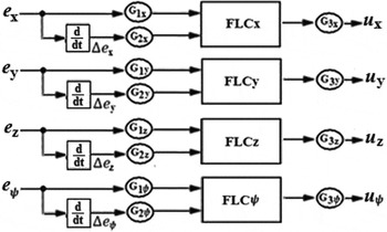
The fuzzy compensation system (Fig. 2) is composed of 12 gains, 4 derivatives and 4 FLCs: FLCx, FLCy, FLCz and FLCψ, where ex = x − xd, ey = y − yd, ez = z − zd , and e ψ = ψ − ψ d , Δex , Δey , Δez and Δe ψ are the derivatives of ex , ey , ez , and e ψ, respectively. The different gains are G 1x = 30, G 1y = 25, G 1z = 1, G 1ψ = 1, G 2x = 8, G 2y = 5, G 2z = 1, G 2ψ = 1, G 3x = 0.6, G 3y = 5, G 3z = 2 and G 3ψ = 1.
Fuzzy compensation system structure.

4.2 Fuzzy logic controller
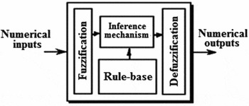
The FLC block diagram(Reference Reznik25,Reference Passino and Yurkovich26) is given in Fig. 3. This fuzzy controller has four main components:
-
1. The fuzzification maps numerical values into linguistic variables matched to membership degrees using a membership function.
-
2. The rule base holds the knowledge, in the form of a set of rules, of how best to control the system. This set of rules consists of linguistic rules with an If-Then structure: If (condition), Then (action).
-
3. The inference engine is the heart of the FLC operation. The inference mechanism evaluates which control rules are relevant at the current time. This inference system applies the rules to the fuzzified values. For each activated rule, the score of the resulting decision is computed.
-
4. The defuzzification interface converts the conclusions reached by the inference mechanism into the inputs to the controlled process. This interface determines the final decision through the intermediate decisions.
Fuzzy controller architecture.

4.3 Used fuzzy controller architecture
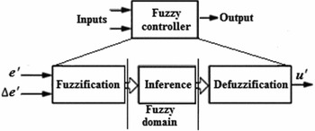
We will choose two inputs for each FLC (Fig. 4) which significantly affect the performance of the considered system. These two parameters are: e' = G 1 e, where e ∈ {ex , ey , ez , e ψ}, and its derivative Δe' = G 2Δe, where Δe ∈ {Δex , Δey , Δez , Δe ψ}. The output of this controller is u' = u/G 3, where G 3 ∈ {G 3x , G 3y , G 3z , G ψ3} and u ∈ {ux , uy , uz , u ψ} is the necessary compensation. The fuzzy controller has a Sugeno-type inference system.
FLC implemented in the compensation system.

4.4 Membership functions
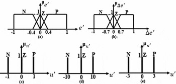
Figure 5 shows different membership functions of each input and each output of different FLCs. Figures 5(a) and 5(b) show, for each FLC, fuzzy subsets of the first input (e') and the second input (Δe'), respectively. The fuzzy subsets of the output of FLCψ (u'), of the output of FLCx and FLCz (u'), and of the output of FLCy (u') are shown in Figs 5(c), 5(d) and 5(e), respectively.
Different membership functions.

4.5 Fuzzy controller's rule base
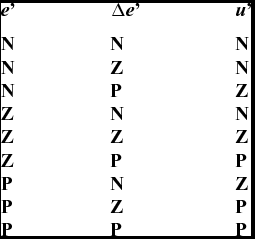
The rule base of each controller is composed of a set of nine fuzzy If-Then rules Ri (i = 1, 2, . . ., 9) of the form: If (e' is a and Δe' is b), Then (u' is c), where a, b, c ∈ {N, Z, P}. Table 1 shows the rule base of all controllers.
Rule base of each FLC

4.6 Simulation results
In fact, the proposed control strategy (Fuzzy Integral Back-Stepping (FIBS) control strategy) is composed of two families of controllers. The first is a model-based controller (IBS controller), and the other family is based on the expert's knowledge on the system (FLC). These controllers are implemented in parallel, and the resulting control signal is sent to the quadrotor system, in which each controller works separately. There is no direct or mathematical coupling between these controllers in order to study the convergence of the global controller. Each controller is derived alone and can work without the need of the other controller.
The main goal of this proposition is to benefit from the advantages of the two controllers which can be resumed as:
-
− The IBS controller is a model-based controller which is characterised by its robustness and good trajectory tracking if the conditions of stability are well respected.
-
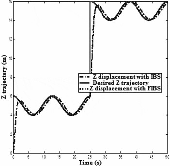
− The FLC provides an algorithm which can convert the linguistic control strategy based on expert knowledge into an automatic control strategy. Experience shows that the FLC yields results superior to those obtained by conventional control algorithms. In particular, the methodology of the FLC appears very useful when the processes are too complex for analysis by conventional quantitative techniques or when the available sources of information are interpreted qualitatively, inexactly or uncertainly. Thus, FLC may be viewed as a step towards a rapprochement between conventional precise mathematical control and human-like decision making. The comparison in the frequency domain of classical linear and non-linear controllers is clearly done in Ref. Reference Awada52. Therefore, the used strategy is to compensate the trajectory tracking error issued due to the model-based controller by a fuzzy compensator. Several simulations have been made to validate our proposed strategy. Different trajectories have been tested, and different types of uncertainities have been added to the simulations. One of the trajectories that we have tested is the following: xd = cos(0.5t), yd = sin(0.5t), ψ d = 0,
${z_d} = \big\{ \scriptsize\begin{array}{@{}l@{}} {\rm{cos}}(0.5t) + 5\;{\rm{if}}\;t \le 25\\ {\rm{cos}}(0.5t) + 15\;{\rm{if}}\;t > 25 \end{array} $
. The idea of choosing this trajectory is to analyse the behaviour of the controller due to step function and then to a sinusoidal function on z, and a sinusoidal function of x and y. So, the trajectory may be considered as a good candidate to test our controller.

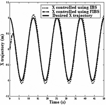
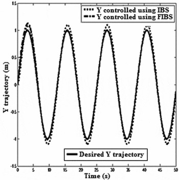
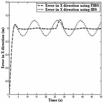
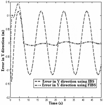
It is clearly seen that the FIBS controller in Figs 6 and 7 reduces the trajectory tracking error. Therefore, the first improvement appears when there is no external disturbances. When an external disturbance is added and represented by the wind effect in the three directions and in magnitude equal to 10 N, excellent improvements can be seen by using the FIBS controller. Figures 6 and 7 show three trajectories: the desired trajectory, the trajectory obtained by using the IBS control and the trajectory obtained by using the FIBS controller. It is seen how the FIBS controller improves the trajectory tracking. It can be see in a more clear view by regarding the errors in Figs 8 and 9. These figures show a good tracking in a short time of convergence.
X displacement with the FIBS controller and the IBS controller.

Y displacement with the FIBS controller and the IBS controller.

Errors in the X direction.

Errors in the Y direction.

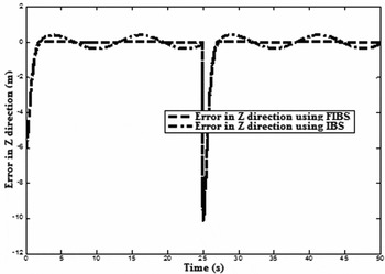
Figure 10 shows the desired trajectory in the z direction, and the trajectory obtained by using the IBS control and the trajectory obtained by using the FIBS controller. It is seen how the FIBS controller improves the trajectory tracking. It can be seen in a more clear view by regarding the errors in Fig. 11.
Z displacement with the FIBS controller and the IBS controller.

Errors in the Z direction.

5.0 CONCLUSION
In this paper, a novel control strategy has been proposed for a quadrotor helicopter. This novel strategy is based on a non-linear based model controller compensated by a fuzzy controller. The back-stepping controller was able to track the trajectory of the well-designed model, and the integral action ensures the minimisation of the steady state error. The unperfectedness of the model and the uncertainties have been compensated by the FLC. The importance of this work resides in the fact that even if the model is not perfect, and in the presence of uncertainties and non-exactness of physical parameters values, the model can track the desired trajectory using a smooth controller. Different trajectories and different conditions such as variation in the wind velocities (and parameters variations) have been tested, and excellent results and excellent improvements regarding classical control theories used have been shown.