




1 Introduction
Rotating flow in the gap between two concentric cylinders, commonly known as Taylor–Couette flow (TCF), is a classic example of a simple system with complex and rich stability properties. On the practical side, TCF occurs in astrophysical accretion discs, turbines and journal bearings. Flow in the gap between two concentric cylinders was first studied by Couette (Reference Couette1890) and Mallock (Reference Mallock1896). The history of early developments in the area is given by Donnelly (Reference Donnelly1991). A tutorial review of TCF is given by Fardin, Perge & Taberlet (Reference Fardin, Perge and Taberlet2014). A recent review paper by Grossmann, Lohse & Sun (Reference Grossmann, Lohse and Sun2016) lists research areas of particular current interest in TCF including instability, nonlinear dynamics, spatio-temporal chaos, pattern formation and turbulence. While TCF has been well studied, however, much remains to be learned about the physics involved.
Geometry and coordinate system of a Taylor–Couette flow. The inner and outer cylinders can rotate in either direction, independently. Also shown are plane Couette flow and Rayleigh–Bénard convection. Gap half-width is denoted as  $\unicode[STIX]{x1D6FF}=0.5(r_{o}-r_{i})$, analogous to the channel half-height in PCF, or half-height in RBC.

As sketched in figure 1, TCF is controlled by six parameters: the kinematic viscosity of the fluid  $\unicode[STIX]{x1D708}$, the inner cylinder radius
 $r_{i}$, the outer cylinder radius
 $r_{o}$, the cylinder height
 $L$, the angular velocity of the inner cylinder
 $\unicode[STIX]{x1D6FA}_{i}$ and that of the outer cylinder
 $\unicode[STIX]{x1D6FA}_{o}$. Dimensional analysis suggests that TCF is governed by four non-dimensional numbers, and a variety of forms have been proposed for defining the non-dimensional numbers, especially the Reynolds number. One commonly used set of non-dimensional numbers is
 $$\begin{eqnarray}\displaystyle & \displaystyle \unicode[STIX]{x1D6F1}_{1}=\unicode[STIX]{x1D6F1}_{r}\stackrel{\text{def}}{=}{\displaystyle \frac{r_{i}}{r_{o}}}; & \displaystyle\end{eqnarray}$$
 $$\begin{eqnarray}\displaystyle & \displaystyle \unicode[STIX]{x1D6F1}_{2}=\unicode[STIX]{x1D6E4}\stackrel{\text{def}}{=}{\displaystyle \frac{L}{2\unicode[STIX]{x1D6FF}}}; & \displaystyle\end{eqnarray}$$
 $$\begin{eqnarray}\displaystyle & \displaystyle \unicode[STIX]{x1D6F1}_{3}=Re_{i}\stackrel{\text{def}}{=}{\displaystyle \frac{(r_{o}-r_{i})r_{i}|\unicode[STIX]{x1D6FA}_{i}|}{\unicode[STIX]{x1D708}}}; & \displaystyle\end{eqnarray}$$
 $$\begin{eqnarray}\displaystyle & \displaystyle \unicode[STIX]{x1D6F1}_{4}=\unicode[STIX]{x1D6F1}_{\unicode[STIX]{x1D6FA}}\stackrel{\text{def}}{=}{\displaystyle \frac{\unicode[STIX]{x1D6FA}_{i}}{\unicode[STIX]{x1D6FA}_{o}}}. & \displaystyle\end{eqnarray}$$
 $\unicode[STIX]{x1D6FF}=0.5(r_{o}-r_{i})$, analogous to the channel half-width in a plane Couette flow (PCF) or the half-height in a Rayleigh–Bénard convection (RBC) cell. The first non-dimensional number
 $\unicode[STIX]{x1D6F1}_{1}$ is a measure of the gap geometry;
 $\unicode[STIX]{x1D6F1}_{2}$ is a measure of the gap height to its width, commonly called the aspect ratio
 $\unicode[STIX]{x1D6E4}$;
 $\unicode[STIX]{x1D6F1}_{3}$ is a definition of the Reynolds number;
 $\unicode[STIX]{x1D6F1}_{4}$ is a measure of the relative rotation of the two cylinders;
 $\unicode[STIX]{x1D6F1}_{\unicode[STIX]{x1D6FA}}=0$ is the special case in which only the outer cylinder rotates and
 $\unicode[STIX]{x1D6F1}_{\unicode[STIX]{x1D6FA}}=\infty$ is the special case in which only the inner cylinder rotates;
 $\unicode[STIX]{x1D6F1}_{\unicode[STIX]{x1D6FA}}<0$ is counter-rotating and
 $\unicode[STIX]{x1D6F1}_{\unicode[STIX]{x1D6FA}}>0$ is co-rotating.
Dubrulle et al. (Reference Dubrulle, Dauchot, Daviaud, Longaretti, Richard and Zahn2005) introduced an alternative set of non-dimensional control parameters, based on dynamic rather than geometric considerations. The development of these new control parameters was motivated by the need to compare flows that do not share identical geometry. For a TCF, Dubrulle et al. (Reference Dubrulle, Dauchot, Daviaud, Longaretti, Richard and Zahn2005) chose the gap width  $2\unicode[STIX]{x1D6FF}$ as the unit length, the inverse of a typical shear
 $S$ as the unit time and
 $\sqrt{r_{i}r_{o}}$ as a typical radius.
Over the past three decades, TCF has been extensively studied experimentally by several research groups, including, for example, Professor Egbers’s group at Brandenburg University of Technology Cottbus-Senftenberg (see Merbold, Brauckmann & Egbers Reference Merbold, Brauckmann and Egbers2013), Professor Lathrop’s group at the University of Maryland (see Zimmerman, Triana & Lathrop Reference Zimmerman, Triana and Lathrop2011), Professor Lohse’s group at the University of Twente (see van Gils et al. Reference van Gils, Bruggert, Lathrop, Sun and Lohse2011), Professor Mutabazi’s group at the Université du Havre (see Martínez-Arias et al. Reference Martínez-Arias, Peixinho, Crumeyrolle and Mutabazi2014), Professor Swinney’s group at the University of Austin (see Andereck, Liu & Swinney Reference Andereck, Liu and Swinney1986) and Professor Westerweel’s group at Delft University of Technology (see Ravelet, Delfos & Westerweel Reference Ravelet, Delfos and Westerweel2010). Their experimental studies have greatly increased our understanding of various aspects of TCF, developed important experimental methods and provided important data sets.
Over the past twenty years, and in particular the past ten years, direct numerical simulation (DNS) has become an important tool in the investigation of TCF. The Reynolds number range achievable in DNS is still lower than that in experimental studies, but DNS can provide detailed data on flows that are challenging to measure experimentally. The analysis in the present work requires the second-order spatial derivative of the mean velocity and the first-order spatial derivative of the Reynolds shear stress, and DNS offers the high resolution and high accuracy to compute those derivatives. Here, several DNS studies are briefly reviewed to provide the simulation parameters and their main findings.
Dong (Reference Dong2007) simulated a TCF system with  $r_{i}/r_{o}=0.5$ and the outer cylinder fixed, covering four Reynolds numbers:
 $Re_{i}=(2\unicode[STIX]{x1D6FF}r_{i}|\unicode[STIX]{x1D6FA}_{i}|)/\unicode[STIX]{x1D708}=1000,3000,5000,8000$. Dong (Reference Dong2007) reported the average axial spacing of the streaks caused by Görtler vortices, and presented flow dynamics and statistics. Dong (Reference Dong2008) simulated a counter-rotating TCF system with
 $r_{i}/r_{o}=0.5$ and documented the statistical features in detail. Dong (Reference Dong2008) demonstrated the effects of the Coriolis force on the mean flow between the standard TCF system (rotating inner cylinder and fixed outer cylinder) and the counter-rotating TCF system.
Pirro & Quadrio (Reference Pirro and Quadrio2008) simulated a small-gap TCF with the outer cylinder at rest. In their simulation, the friction Reynolds number based on the friction velocity at the inner cylinder  $u_{\unicode[STIX]{x1D70F},i}$ is
 $Re_{\unicode[STIX]{x1D70F},i}\stackrel{\text{def}}{=}\unicode[STIX]{x1D6FF}u_{\unicode[STIX]{x1D70F},i}/\unicode[STIX]{x1D708}=189.3$ for the inner cylinder half and the friction Reynolds number based on the friction velocity at the outer cylinder
 $u_{\unicode[STIX]{x1D70F},o}$ is
 $Re_{\unicode[STIX]{x1D70F},o}\stackrel{\text{def}}{=}\unicode[STIX]{x1D6FF}u_{\unicode[STIX]{x1D70F},o}/\unicode[STIX]{x1D708}=167.7$ for the outer cylinder half. They reported the profiles of the mean azimuthal velocity, and the variance of velocity fluctuations in the radial, azimuthal and axial directions.
Ostilla–Monico and collaborators (Ostilla-Mónico et al. Reference Ostilla-Mónico, Stevens, Grossmann, Verzicco and Lohse2013, Reference Ostilla-Mónico, Huisman, Jannink, Van Gils, Verzicco, Grossmann, Sun and Lohse2014; Ostilla-Mónico, Verzicco & Lohse Reference Ostilla-Mónico, Verzicco and Lohse2015) have performed extensive DNS studies to examine the effect of computational domain size and radial ratio. To save simulation time, some of their simulations used a quarter of the domain, employing rotational symmetry of order four (Ostilla-Mónico et al. Reference Ostilla-Mónico, Stevens, Grossmann, Verzicco and Lohse2013). They examined the mean and fluctuation velocities, as well as autocorrelations and velocity spectra. The smallest domain size was found to accurately reproduce the torque and mean azimuthal velocity profiles of the larger domain, but produced smaller values of fluctuations than the larger domain size simulation.
Brauckmann & Eckhardt (Reference Brauckmann and Eckhardt2013) performed DNS of TCF using a spectral code with periodic boundary conditions in the axial direction and aspect ratio  $\unicode[STIX]{x1D6E4}=2$. They found a maximum in the angular velocity transport for the counter-rotation with
 $-\unicode[STIX]{x1D6FA}_{o}/\unicode[STIX]{x1D6FA}_{i}\approx 0.4$. Tanaka, Kawata & Tsukahara (Reference Tanaka, Kawata and Tsukahara2018) performed a series of simulations of a counter-rotating TCF system with relatively small radius ratios
 $r_{i}/r_{o}=0.2{-}0.5$. They investigated the effect of radius ratio on the flow state. Tanaka et al. (Reference Tanaka, Kawata and Tsukahara2018) observed that at small radius ratio, the Reynolds shear stress on the outer side remained approximately zero, but the intensity of the velocity fluctuations was comparable to that of the Taylor-vortex flow in the central region.
DNS data have been used to explore various aspects of TCF. However, a systematic scaling analysis of the mean momentum balance equation in TCF is still lacking, and this is the motivation of the present work. The rest of this paper is organized as follows. In § 2, the governing equations of the TCF are presented. For a fully developed turbulent TCF, the Reynolds averaged equations in the radial and azimuthal directions are presented. The properties of the Reynolds shear stress and the turbulent Coriolis force are revealed by integrating the mean momentum equation. In § 3, a layer structure is proposed for a turbulent TCF based on the characteristics of the force balance. The scaling analysis leads to new non-dimensional numbers for  $\unicode[STIX]{x1D6F1}_{1}$ and
 $\unicode[STIX]{x1D6F1}_{3}$. An outer scaling and an inner scaling are developed for the outer layer and inner layer, respectively. In § 4, the limitations of the analysis, along with areas for future investigation, are discussed. Section 5 summarizes the work.
2 Governing equations
The continuity equation and Navier–Stokes equations in a cylindrical coordinate system are (Townsend Reference Townsend1980; Landau & Lifshitz Reference Landau and Lifshitz1987; Schlichting & Gersten Reference Schlichting and Gersten2016)
 $$\begin{eqnarray}\displaystyle & & \displaystyle \hspace{-12.0pt}0={\displaystyle \frac{\unicode[STIX]{x2202}\tilde{u} _{r}}{\unicode[STIX]{x2202}r}}+{\displaystyle \frac{\tilde{u} _{r}}{r}}+{\displaystyle \frac{1}{r}}{\displaystyle \frac{\unicode[STIX]{x2202}\tilde{u} _{\unicode[STIX]{x1D719}}}{\unicode[STIX]{x2202}\unicode[STIX]{x1D719}}}+{\displaystyle \frac{\unicode[STIX]{x2202}\tilde{u} _{x}}{\unicode[STIX]{x2202}x}};\quad \text{Continuity}\end{eqnarray}$$
 $$\begin{eqnarray}\displaystyle & & \displaystyle \hspace{-12.0pt}{\displaystyle \frac{\unicode[STIX]{x2202}\tilde{u} _{r}}{\unicode[STIX]{x2202}t}}+{\displaystyle \frac{\unicode[STIX]{x2202}(\tilde{u} _{r}\tilde{u} _{r})}{\unicode[STIX]{x2202}r}}+{\displaystyle \frac{1}{r}}{\displaystyle \frac{\unicode[STIX]{x2202}(\tilde{u} _{\unicode[STIX]{x1D719}}\tilde{u} _{r})}{\unicode[STIX]{x2202}\unicode[STIX]{x1D719}}}+{\displaystyle \frac{\unicode[STIX]{x2202}(\tilde{u} _{x}\tilde{u} _{r})}{\unicode[STIX]{x2202}x}}+{\displaystyle \frac{\tilde{u} _{r}\tilde{u} _{r}-\tilde{u} _{\unicode[STIX]{x1D719}}\tilde{u} _{\unicode[STIX]{x1D719}}}{r}}\nonumber\\ \displaystyle & & \displaystyle \hspace{-12.0pt}\quad =-{\displaystyle \frac{\unicode[STIX]{x2202}}{\unicode[STIX]{x2202}r}}\!\left({\displaystyle \frac{\tilde{p}}{\unicode[STIX]{x1D70C}}}\right)\!+\unicode[STIX]{x1D708}\!\left\{\!{\displaystyle \frac{\unicode[STIX]{x2202}^{2}\tilde{u} _{r}}{\unicode[STIX]{x2202}r^{2}}}+{\displaystyle \frac{1}{r}}{\displaystyle \frac{\unicode[STIX]{x2202}\tilde{u} _{r}}{\unicode[STIX]{x2202}r}}-{\displaystyle \frac{\tilde{u} _{r}}{r^{2}}}+{\displaystyle \frac{1}{r^{2}}}{\displaystyle \frac{\unicode[STIX]{x2202}^{2}\tilde{u} _{r}}{\unicode[STIX]{x2202}\unicode[STIX]{x1D719}^{2}}}+{\displaystyle \frac{\unicode[STIX]{x2202}^{2}\tilde{u} _{r}}{\unicode[STIX]{x2202}x^{2}}}-{\displaystyle \frac{2}{r^{2}}}{\displaystyle \frac{\unicode[STIX]{x2202}\tilde{u} _{\unicode[STIX]{x1D719}}}{\unicode[STIX]{x2202}\unicode[STIX]{x1D719}}}\!\right\}\!;\quad \text{NS}\text{-}r\end{eqnarray}$$
 $$\begin{eqnarray}\displaystyle & & \displaystyle \hspace{-12.0pt}{\displaystyle \frac{\unicode[STIX]{x2202}\tilde{u} _{\unicode[STIX]{x1D719}}}{\unicode[STIX]{x2202}t}}+{\displaystyle \frac{\unicode[STIX]{x2202}(\tilde{u} _{r}\tilde{u} _{\unicode[STIX]{x1D719}})}{\unicode[STIX]{x2202}r}}+{\displaystyle \frac{1}{r}}{\displaystyle \frac{\unicode[STIX]{x2202}(\tilde{u} _{\unicode[STIX]{x1D719}}\tilde{u} _{\unicode[STIX]{x1D719}})}{\unicode[STIX]{x2202}\unicode[STIX]{x1D719}}}+{\displaystyle \frac{\unicode[STIX]{x2202}(\tilde{u} _{x}\tilde{u} _{\unicode[STIX]{x1D719}})}{\unicode[STIX]{x2202}x}}+{\displaystyle \frac{2\tilde{u} _{r}\tilde{u} _{\unicode[STIX]{x1D719}}}{r}}\nonumber\\ \displaystyle & & \displaystyle \hspace{-12.0pt}\quad =-{\displaystyle \frac{1}{r}}{\displaystyle \frac{\unicode[STIX]{x2202}}{\unicode[STIX]{x2202}\unicode[STIX]{x1D719}}}\left({\displaystyle \frac{\tilde{p}}{\unicode[STIX]{x1D70C}}}\right)+\unicode[STIX]{x1D708}\left\{{\displaystyle \frac{\unicode[STIX]{x2202}^{2}\tilde{u} _{\unicode[STIX]{x1D719}}}{\unicode[STIX]{x2202}r^{2}}}+{\displaystyle \frac{1}{r}}{\displaystyle \frac{\unicode[STIX]{x2202}\tilde{u} _{\unicode[STIX]{x1D719}}}{\unicode[STIX]{x2202}r}}-{\displaystyle \frac{\tilde{u} _{\unicode[STIX]{x1D719}}}{r^{2}}}+{\displaystyle \frac{1}{r^{2}}}{\displaystyle \frac{\unicode[STIX]{x2202}^{2}\tilde{u} _{\unicode[STIX]{x1D719}}}{\unicode[STIX]{x2202}\unicode[STIX]{x1D719}^{2}}}+{\displaystyle \frac{\unicode[STIX]{x2202}^{2}\tilde{u} _{\unicode[STIX]{x1D719}}}{\unicode[STIX]{x2202}x^{2}}}+{\displaystyle \frac{2}{r^{2}}}{\displaystyle \frac{\unicode[STIX]{x2202}\tilde{u} _{r}}{\unicode[STIX]{x2202}\unicode[STIX]{x1D719}}}\right\}\!;\quad \text{NS}\text{-}\unicode[STIX]{x1D719}\nonumber\\ \displaystyle & & \displaystyle\end{eqnarray}$$
 $$\begin{eqnarray}\displaystyle & & \displaystyle \hspace{-12.0pt}{\displaystyle \frac{\unicode[STIX]{x2202}\tilde{u} _{x}}{\unicode[STIX]{x2202}t}}+{\displaystyle \frac{\unicode[STIX]{x2202}(\tilde{u} _{r}\tilde{u} _{x})}{\unicode[STIX]{x2202}r}}+{\displaystyle \frac{1}{r}}{\displaystyle \frac{\unicode[STIX]{x2202}(\tilde{u} _{\unicode[STIX]{x1D719}}\tilde{u} _{x})}{\unicode[STIX]{x2202}\unicode[STIX]{x1D719}}}+{\displaystyle \frac{\unicode[STIX]{x2202}(\tilde{u} _{x}\tilde{u} _{x})}{\unicode[STIX]{x2202}x}}+{\displaystyle \frac{\tilde{u} _{r}\tilde{u} _{x}}{r}}\nonumber\\ \displaystyle & & \displaystyle \hspace{-12.0pt}\quad =-{\displaystyle \frac{\unicode[STIX]{x2202}}{\unicode[STIX]{x2202}x}}\left({\displaystyle \frac{\tilde{p}}{\unicode[STIX]{x1D70C}}}\right)+\unicode[STIX]{x1D708}\left\{{\displaystyle \frac{\unicode[STIX]{x2202}^{2}\tilde{u} _{x}}{\unicode[STIX]{x2202}r^{2}}}+{\displaystyle \frac{1}{r}}{\displaystyle \frac{\unicode[STIX]{x2202}\tilde{u} _{x}}{\unicode[STIX]{x2202}r}}+{\displaystyle \frac{1}{r^{2}}}{\displaystyle \frac{\unicode[STIX]{x2202}^{2}\tilde{u} _{x}}{\unicode[STIX]{x2202}\unicode[STIX]{x1D719}^{2}}}+{\displaystyle \frac{\unicode[STIX]{x2202}^{2}\tilde{u} _{x}}{\unicode[STIX]{x2202}x^{2}}}\right\}\!.\quad \text{NS}\text{-}x\end{eqnarray}$$
Here,  $r$ is the radial direction,
 $\unicode[STIX]{x1D719}$ is the azimuthal direction and
 $x$ is the axial direction;
 $\unicode[STIX]{x1D70C}$ is the fluid density. Note that the continuity (2.1a) is used to present the momentum equations (2.1b)–(2.1d) in a conservation form, for the convenience of performing the Reynolds averaging operation. In the present work, the instantaneous variable is denoted by a tilde, an upper case letter denotes its mean and a lower case letter denotes its fluctuation. For example, in
 $\tilde{u} _{\unicode[STIX]{x1D719}}=U_{\unicode[STIX]{x1D719}}+u_{\unicode[STIX]{x1D719}}$,
 $\tilde{u} _{\unicode[STIX]{x1D719}}$ is the instantaneous azimuthal velocity,
 $U_{\unicode[STIX]{x1D719}}$ is the mean azimuthal velocity and
 $u_{\unicode[STIX]{x1D719}}$ is the azimuthal velocity fluctuation.
The present work assumes that the turbulent TCF is statistically homogeneous in the axial  $x$ direction. In other words, it is assumed that the height of the cylinders is much larger than the gap width or
 $\unicode[STIX]{x1D6E4}\gg 10$ (see Chouippe et al. Reference Chouippe, Climent, Legendre and Gabillet2014). For a fully developed turbulent TCF, the only non-zero component of mean velocity is in the azimuthal
 $\unicode[STIX]{x1D719}$ direction, and the mean values depend only on the radial location:
 $U_{r}=U_{x}=0$,
 $\unicode[STIX]{x2202}/\unicode[STIX]{x2202}\unicode[STIX]{x1D719}=0$ and
 $\unicode[STIX]{x2202}/\unicode[STIX]{x2202}x=0$ (Townsend Reference Townsend1980).
For Navier–Stokes equations in a cylindrical coordinate system, the viscous shear stress is (see Taylor Reference Taylor1936; Landau & Lifshitz Reference Landau and Lifshitz1987)
 $$\begin{eqnarray}\unicode[STIX]{x1D70F}_{r\unicode[STIX]{x1D719}}=\unicode[STIX]{x1D707}\left({\displaystyle \frac{1}{r}}{\displaystyle \frac{\unicode[STIX]{x2202}U_{r}}{\unicode[STIX]{x2202}\unicode[STIX]{x1D719}}}+{\displaystyle \frac{\unicode[STIX]{x2202}U_{\unicode[STIX]{x1D719}}}{\unicode[STIX]{x2202}r}}-{\displaystyle \frac{U_{\unicode[STIX]{x1D719}}}{r}}\right).\end{eqnarray}$$
For a fully developed turbulent TCF, the first term on the right side of (2.2) is zero. In the present work, the positive  $\unicode[STIX]{x1D719}$ direction is defined such that
 $\text{d}U_{\unicode[STIX]{x1D719}}/\text{d}r$ is negative. For example, if only the inner cylinder is rotating, the positive azimuthal direction is the direction of rotation. If only the outer cylinder is rotating, the positive azimuthal direction is the direction opposite the direction of rotation. Under such a coordinate system, the mean azimuthal velocity decreases in the radial direction and the Reynolds shear stress is negative.
Using the convention commonly followed for turbulent wall-bounded flows (see Tennekes & Lumley Reference Tennekes and Lumley1972), the friction velocities at the inner cylinder and outer cylinder, respectively, are defined as
 $$\begin{eqnarray}\displaystyle & \displaystyle u_{\unicode[STIX]{x1D70F},i}\stackrel{\text{def}}{=}\sqrt{{\displaystyle \frac{|\unicode[STIX]{x1D70F}_{r\unicode[STIX]{x1D719}}|_{r=r_{i}}}{\unicode[STIX]{x1D70C}}}}=\sqrt{\unicode[STIX]{x1D708}\Big|{\displaystyle \frac{\text{d}U_{\unicode[STIX]{x1D719}}}{\text{d}r}}-{\displaystyle \frac{U_{\unicode[STIX]{x1D719}}}{r}}\Big|_{r=r_{i}}}; & \displaystyle\end{eqnarray}$$
 $$\begin{eqnarray}\displaystyle & \displaystyle u_{\unicode[STIX]{x1D70F},o}\stackrel{\text{def}}{=}\sqrt{{\displaystyle \frac{|\unicode[STIX]{x1D70F}_{r\unicode[STIX]{x1D719}}|_{r=r_{o}}}{\unicode[STIX]{x1D70C}}}}=\sqrt{\unicode[STIX]{x1D708}\Big|{\displaystyle \frac{\text{d}U_{\unicode[STIX]{x1D719}}}{\text{d}r}}-{\displaystyle \frac{U_{\unicode[STIX]{x1D719}}}{r}}\Big|_{r=r_{o}}}. & \displaystyle\end{eqnarray}$$
The moment (or torque) at the inner cylinder is  $M_{i}=(2\unicode[STIX]{x03C0}rL\unicode[STIX]{x1D70F}_{r\unicode[STIX]{x1D719}}r)_{r=r_{i}}$, and the moment (or torque) at the outer cylinder is
 $M_{o}=(2\unicode[STIX]{x03C0}rL\unicode[STIX]{x1D70F}_{r\unicode[STIX]{x1D719}}r)_{r=r_{o}}$. Substituting the definitions of the friction velocities in (2.3a) and (2.3b), the moment at the inner cylinder can be expressed as
 $|M_{i}|=2\unicode[STIX]{x03C0}r_{i}^{2}L\unicode[STIX]{x1D70C}u_{\unicode[STIX]{x1D70F},i}^{2}$, and the moment at the outer cylinder can be expressed as
 $|M_{o}|=2\unicode[STIX]{x03C0}r_{o}^{2}L\unicode[STIX]{x1D70C}u_{\unicode[STIX]{x1D70F},o}^{2}$.
For a TCF system in a statistical steady state, global moment (or torque) balance, analogous to the force balance in a plane Couette flow, dictates  $M_{i}=-M_{o}$ or
 $$\begin{eqnarray}2\unicode[STIX]{x03C0}r_{i}^{2}L\unicode[STIX]{x1D70C}u_{\unicode[STIX]{x1D70F},i}^{2}=2\unicode[STIX]{x03C0}r_{o}^{2}L\unicode[STIX]{x1D70C}u_{\unicode[STIX]{x1D70F},o}^{2}.\end{eqnarray}$$
Hence, the friction velocity at the inner cylinder and outer cylinder are related to each other as
 $$\begin{eqnarray}{\displaystyle \frac{u_{\unicode[STIX]{x1D70F},i}}{u_{\unicode[STIX]{x1D70F},o}}}={\displaystyle \frac{r_{o}}{r_{i}}}.\end{eqnarray}$$
Therefore, the wall shear stress or friction velocity at the inner cylinder is always larger than at the outer cylinder, regardless of which cylinder is rotating or the rotation ratio. In the sketch of mean azimuthal velocity in figure 1, the velocity profile is steeper near the inner cylinder than near the outer cylinder.
For a steady state turbulent TCF, Reynolds averaging is both time averaging and plane averaging in the  $\unicode[STIX]{x1D719}{-}x$ plane. Applying Reynolds averaging, the mean momentum balance equation in the
 $r$ direction (MMB-
 $r$) and
 $\unicode[STIX]{x1D719}$ direction (MMB-
 $\unicode[STIX]{x1D719}$) can be expressed as
 $$\begin{eqnarray}\displaystyle & \displaystyle 0=\underbrace{-{\displaystyle \frac{\text{d}}{\text{d}r}}\left({\displaystyle \frac{P}{\unicode[STIX]{x1D70C}}}\right)}_{F_{pres}}+\underbrace{{\displaystyle \frac{\text{d}R_{rr}}{\text{d}r}}}_{F_{turb\text{-}r}}+\underbrace{{\displaystyle \frac{U_{\unicode[STIX]{x1D719}}U_{\unicode[STIX]{x1D719}}+R_{rr}-R_{\unicode[STIX]{x1D719}\unicode[STIX]{x1D719}}}{r}}}_{F_{cent}};\quad \text{MMB-}r & \displaystyle\end{eqnarray}$$
 $$\begin{eqnarray}\displaystyle & \displaystyle 0=\underbrace{\unicode[STIX]{x1D708}\left\{{\displaystyle \frac{\text{d}^{2}U_{\unicode[STIX]{x1D719}}}{\text{d}r^{2}}}+{\displaystyle \frac{1}{r}}{\displaystyle \frac{\text{d}U_{\unicode[STIX]{x1D719}}}{\text{d}r}}-{\displaystyle \frac{U_{\unicode[STIX]{x1D719}}}{r^{2}}}\right\}}_{F_{visc}}+\underbrace{{\displaystyle \frac{\text{d}R_{r\unicode[STIX]{x1D719}}}{\text{d}r}}}_{F_{turb\text{-}\unicode[STIX]{x1D719}}}+\underbrace{{\displaystyle \frac{2R_{r\unicode[STIX]{x1D719}}}{r}}}_{F_{cori}},\quad \text{MMB-}\unicode[STIX]{x1D719} & \displaystyle\end{eqnarray}$$
 $R_{rr}=-\langle u_{r}u_{r}\rangle$ and
 $R_{\unicode[STIX]{x1D719}\unicode[STIX]{x1D719}}=-\langle u_{\unicode[STIX]{x1D719}}u_{\unicode[STIX]{x1D719}}\rangle$ are the kinematic Reynolds normal stresses in the
 $r$ and
 $\unicode[STIX]{x1D719}$ directions, respectively. Here,
 $R_{r\unicode[STIX]{x1D719}}=-\langle u_{r}u_{\unicode[STIX]{x1D719}}\rangle$ is the kinematic Reynolds shear stress. Angle brackets
 $\langle \;\rangle$ denote Reynolds averaging.
The MMB- $r$ equation (2.6a) represents the balance of three forces in the radial
 $r$ direction: a pressure force
 $F_{pres}$, a Reynolds normal force
 $F_{turb\text{-}r}$ and a centrifugal force
 $F_{cent}$. The pressure force and the Reynolds normal forces are analogous to those in the wall-normal direction of a turbulent pipe or channel flow. The centrifugal force consists of two parts: one from the mean flow
 $(U_{\unicode[STIX]{x1D719}}U_{\unicode[STIX]{x1D719}})/r$ and another from the turbulence
 $(R_{rr}-R_{\unicode[STIX]{x1D719}\unicode[STIX]{x1D719}})/r$. The MMB-
 $r$ equation (2.6a) can be used to determine the mean pressure distribution in the TCF system. In the present work, we will focus on the properties of the mean momentum balance equation in the azimuthal direction, which is analogous to the streamwise direction in a turbulent pipe or channel flow.
The MMB- $\unicode[STIX]{x1D719}$ equation (2.6b) represents the balance of three forces in the
 $\unicode[STIX]{x1D719}$ direction: a viscous force
 $F_{visc}$, a Reynolds shear force
 $F_{turb\text{-}\unicode[STIX]{x1D719}}$ and a turbulent Coriolis force
 $F_{cori}$. In the present work, the MMB-
 $\unicode[STIX]{x1D719}$ equation (2.6b) is analysed to reveal the properties of the Reynolds shear stress, the turbulent Coriolis force and the layer structure of a turbulent TCF. A multiscaling analysis of the MMB-
 $\unicode[STIX]{x1D719}$ equation (2.6b) is then developed and verified by DNS data.
2.1 Properties of the Reynolds shear stress
Multiplying the MMB- $\unicode[STIX]{x1D719}$ equation (2.6b) by
 $r^{2}$, simple mathematical manipulation gives
 $$\begin{eqnarray}0={\displaystyle \frac{\text{d}}{\text{d}r}}\left(r^{2}\unicode[STIX]{x1D708}\left({\displaystyle \frac{\text{d}U_{\unicode[STIX]{x1D719}}}{\text{d}r}}-{\displaystyle \frac{U_{\unicode[STIX]{x1D719}}}{r}}\right)\right)+{\displaystyle \frac{\text{d}(r^{2}R_{r\unicode[STIX]{x1D719}})}{\text{d}r}}.\end{eqnarray}$$
Equation (2.7) is equivalent to (9.2.1.) in Townsend (Reference Townsend1980), and is also essentially the same as (3.3) in Eckhardt, Grossmann & Lohse (Reference Eckhardt, Grossmann and Lohse2007).
In a fully developed turbulent TCF, the moment of the viscous shear stress is
 $$\begin{eqnarray}M_{visc}=2\unicode[STIX]{x03C0}rL\unicode[STIX]{x1D70F}_{r\unicode[STIX]{x1D719}}r=(2\unicode[STIX]{x03C0}L\unicode[STIX]{x1D70C})r^{2}\unicode[STIX]{x1D708}\left({\displaystyle \frac{\text{d}U_{\unicode[STIX]{x1D719}}}{\text{d}r}}-{\displaystyle \frac{U_{\unicode[STIX]{x1D719}}}{r}}\right),\end{eqnarray}$$
and the moment of the Reynolds shear stress is
 $$\begin{eqnarray}M_{turb}=2\unicode[STIX]{x03C0}rL\unicode[STIX]{x1D70C}R_{r\unicode[STIX]{x1D719}}r=(2\unicode[STIX]{x03C0}L\unicode[STIX]{x1D70C})r^{2}R_{r\unicode[STIX]{x1D719}}.\end{eqnarray}$$
Hence, equation (2.7) can be presented in the form of moment as
 $$\begin{eqnarray}0={\displaystyle \frac{\text{d}M_{visc}}{\text{d}r}}+{\displaystyle \frac{\text{d}M_{turb}}{\text{d}r}}.\end{eqnarray}$$
Integrating the mean momentum equation (2.7) or (2.10) in the wall-normal direction from the inner cylinder and applying boundary conditions yields
 $$\begin{eqnarray}r^{2}\unicode[STIX]{x1D708}\left({\displaystyle \frac{\text{d}U_{\unicode[STIX]{x1D719}}}{\text{d}r}}-{\displaystyle \frac{U_{\unicode[STIX]{x1D719}}}{r}}\right)+r^{2}R_{r\unicode[STIX]{x1D719}}=r^{2}\unicode[STIX]{x1D708}\left({\displaystyle \frac{\text{d}U_{\unicode[STIX]{x1D719}}}{\text{d}r}}-{\displaystyle \frac{U_{\unicode[STIX]{x1D719}}}{r}}\right)\Big|_{r=r_{i}}+(r^{2}R_{r\unicode[STIX]{x1D719}})\big|_{r=ri}=-r_{i}^{2}u_{\unicode[STIX]{x1D70F},i}^{2}.\end{eqnarray}$$
Note that the Reynolds shear stress at the inner cylinder is zero for a turbulent TCF with smooth walls. As mentioned in the previous section, the coordinate system is set up such that the mean azimuthal velocity gradient and the Reynolds shear stress are both negative. Thus, the total moment is also negative. Equation (2.11) is equivalent to (9.2.2) in Townsend (Reference Townsend1980), and is also essentially the same as the identity equation (3.4) in Eckhardt et al. (Reference Eckhardt, Grossmann and Lohse2007). Townsend (Reference Townsend1980) interpreted equation (2.11) as follows: ‘the sum of the ‘couples’ transmitted by viscous and turbulent stress across surfaces of constant radius is independent of the radius’. Eckhardt et al. (Reference Eckhardt, Grossmann and Lohse2007) called the constant the angular velocity current. Here, a simple interpretation of (2.11) is that the total moment (per  $2\unicode[STIX]{x03C0}\unicode[STIX]{x1D70C}L$), viscous plus turbulent
 $M_{visc}+M_{turb}$, is a constant, independent of the radial location. The constancy of (2.11) has been used as a consistency check for DNS simulations, as by Dong (Reference Dong2008).
To establish a turbulent plane Couette flow, one can move the top plate only, or the bottom plate only or move both plates in the same direction or opposite direction. However, the total shear stress, viscous plus turbulent  $\unicode[STIX]{x1D70F}_{wu}+R_{wu}$, is always a constant across the channel, regardless of how the top and bottom plates are being moved. Similarly, equation (2.11) also indicates that the total moment in a turbulent TCF is always a constant, regardless of
 $\unicode[STIX]{x1D6F1}_{\unicode[STIX]{x1D6FA}}$ or how the inner and outer cylinders are being rotated.
In turbulent channel or boundary layer flows, viscous shear stress peaks at the wall and decreases rapidly away from the wall. In a turbulent TCF, the moment of viscous shear stress also peaks at the wall and decreases rapidly along the wall-normal direction. Away from the wall, the viscous term in the integrated MMB- $\unicode[STIX]{x1D719}$ (2.11) becomes negligible and the Reynolds shear stress can be approximated as
 $$\begin{eqnarray}R_{r\unicode[STIX]{x1D719}}\approx -{\displaystyle \frac{r_{i}^{2}}{r^{2}}}u_{\unicode[STIX]{x1D70F},i}^{2}.\quad \text{Core Region}\end{eqnarray}$$
Hence, Reynolds shear stress in the core of a highly turbulent TCF decreases in a  $1/r^{2}$ fashion along the radial direction.
Following the convention commonly followed for turbulent wall-bounded flows, the Reynolds shear stress normalized by  $u_{\unicode[STIX]{x1D70F},i}^{2}$ is denoted as
 $R_{r\unicode[STIX]{x1D719}}^{+}=R_{r\unicode[STIX]{x1D719}}/u_{\unicode[STIX]{x1D70F},i}^{2}$. Equation (2.12) in the non-dimensional form can be presented as
 $$\begin{eqnarray}\displaystyle & \displaystyle R_{r\unicode[STIX]{x1D719}}^{+}\approx -\left({\displaystyle \frac{r_{i}}{r}}\right)^{2}=-\left({\displaystyle \frac{1}{1+{\displaystyle \frac{\unicode[STIX]{x1D6FF}}{r_{i}}}z^{-}}}\right)^{2}=-\left({\displaystyle \frac{1-A_{t}}{1-A_{t}+A_{t}z^{-}}}\right)^{2}, & \displaystyle\end{eqnarray}$$
 $$\begin{eqnarray}\displaystyle & \displaystyle \text{or}\quad \left({\displaystyle \frac{r}{r_{i}}}\right)^{2}R_{r\unicode[STIX]{x1D719}}^{+}\approx -1. & \displaystyle\end{eqnarray}$$
 $z^{-}$ and
 $A_{t}$ are defined as
 $$\begin{eqnarray}\displaystyle & \displaystyle z^{-}\stackrel{\text{def}}{=}{\displaystyle \frac{r-r_{i}}{0.5(r_{o}-r_{i})}}={\displaystyle \frac{r-r_{i}}{\unicode[STIX]{x1D6FF}}}; & \displaystyle\end{eqnarray}$$
 $$\begin{eqnarray}\displaystyle & \displaystyle A_{t}\stackrel{\text{def}}{=}{\displaystyle \frac{\unicode[STIX]{x1D6FF}}{r_{ctr}}}={\displaystyle \frac{0.5(r_{o}-r_{i})}{0.5(r_{o}+r_{i})}}. & \displaystyle\end{eqnarray}$$
 $\unicode[STIX]{x1D702}$ (see, e.g. Tennekes & Lumley (Reference Tennekes and Lumley1972)). However,
 $\unicode[STIX]{x1D702}$ has been used in previous studies of TCF to denote the ratio of the cylinder radii. In the present work, a new notation
 $z^{-}$ is introduced to denote the wall-normal distance
 $r-r_{i}$ scaled by the TCF gap half-width
 $\unicode[STIX]{x1D6FF}$.
The definition of  $A_{t}$ in (2.14b) is analogous to the Atwood number used in the study of hydrodynamic instability in density stratified flows, such as Rayleigh–Taylor instability (Glimm et al. Reference Glimm, Grove, Li, Oh and Sharp2001; Livescu et al. Reference Livescu, Ristorcelli, Gore, Dean, Cabot and Cook2009; Wei & Livescu Reference Wei and Livescu2012), see appendix A. In the present work, therefore, this non-dimensional number is called a geometry Atwood number.
(a) Reynolds shear stress in a Taylor–Couette flow. The curve is (2.13a). Data are from DNS of Dong (Reference Dong2008), with  $r_{i}/r_{o}=0.5$ or
 $A_{t}=1/3$. (b)
 $-(r/r_{i})^{2}R_{r\unicode[STIX]{x1D719}}^{+}$ versus the wall-normal distance scaled by the TCF gap half-width
 $z^{-}$. The PCF data are from DNS of Kawamura, Abe & Shingai (Reference Kawamura, Abe and Shingai2000) at
 $Re_{\unicode[STIX]{x1D70F}}=181$.

The approximate equation (2.13a) for the Reynolds shear stress is compared with DNS data of Dong (Reference Dong2008) in figure 2. The DNS is for the same gap geometry with  $A_{t}=1/3$, and four different Reynolds numbers. At
 $Re_{\unicode[STIX]{x1D70F},i}=\unicode[STIX]{x1D6FF}u_{\unicode[STIX]{x1D70F},i}/\unicode[STIX]{x1D708}=32.7$, the Reynolds shear stress profile in the core of the gap deviates from (2.13a), because at such a low Reynolds number, turbulence is still not well established and the viscous shear stress is not negligible in the outer layer. However, at higher Reynolds numbers,
 $Re_{\unicode[STIX]{x1D70F},i}>74$, DNS data of Reynolds shear stress in the core of the gap agree well with (2.13a), supporting the validity of the analysis.
In figure 2(b), the approximate equation (2.13b) is compared with the DNS data of TCF; the Reynolds shear stress in a turbulent PCF is also plotted. The PCF data are from Kawamura’s group at  $Re_{\unicode[STIX]{x1D70F}}=181.3$ (Kawamura et al. Reference Kawamura, Abe and Shingai2000; Shingai, Kawamura & Matsuo Reference Shingai, Kawamura, Matsuo and Dopazo2000; Tsukahara, Kawamura & Shingai Reference Tsukahara, Kawamura and Shingai2006). Figure 2(b) displays the resemblance between the turbulent TCF and PCF, and in particular in the inner half next to the inner cylinder. Near the outer cylinder,
 $-(r/r_{i})^{2}R_{r\unicode[STIX]{x1D719}}^{+}$ is different from the Reynolds shear stress in a turbulent plane Couette flow, but the difference becomes smaller as the Reynolds number increases.
In a turbulent plane Couette flow, the Reynolds shear stress is symmetric about the gap centreline, with a peak at the middle. In a turbulent TCF, the mid-gap is located at  $r_{ctr}=0.5(r_{i}+r_{0})$, and its Reynolds shear stress can be approximated as
 $$\begin{eqnarray}R_{r\unicode[STIX]{x1D719}}|_{ctr}\approx -\left({\displaystyle \frac{r_{i}}{0.5(r_{i}+r_{o})}}\right)^{2}u_{\unicode[STIX]{x1D70F},i}^{2}=-(1-A_{t})^{2}u_{\unicode[STIX]{x1D70F},i}^{2}.\end{eqnarray}$$
Hence, the magnitude of the Reynolds shear stress at the mid-gap of a turbulent TCF is always smaller than  $u_{\unicode[STIX]{x1D70F},i}^{2}$ or
 $|R_{r\unicode[STIX]{x1D719}}^{+}|\leqslant 1$. As the geometry Atwood number approaches zero
 $A_{t}\rightarrow 0$ or the small-gap limit, the Reynolds shear stress at the mid-gap approaches the kinematic wall shear stress at the inner cylinder
 $|R_{r\unicode[STIX]{x1D719}}|_{ctr}\approx u_{\unicode[STIX]{x1D70F},i}^{2}$, and the turbulent TCF becomes similar to a turbulent plane Couette flow. However, at a large geometry Atwood number
 $A_{t}\rightarrow 1$, the magnitude of the Reynolds shear stress is much smaller than
 $u_{\unicode[STIX]{x1D70F},i}^{2}$ or
 $|R_{r\unicode[STIX]{x1D719}}^{+}|\ll 1$, as shown figure 3(a).
Effects of geometry Atwood number  $A_{t}$ on the shape of Reynolds shear stress in TCF. (a)
 $-R_{r\unicode[STIX]{x1D719}}^{+}$ versus
 $z^{-}$. The curve is the approximate equation (2.13a). Data for
 $A_{t}=0.333$ are from DNS of Dong (Reference Dong2008). Data for
 $A_{t}=0.43$,
 $0.54$ and
 $0.667$ are from DNS of Tanaka et al. (Reference Tanaka, Kawata and Tsukahara2018). (b)
 $-(r/r_{i})^{2}R_{r\unicode[STIX]{x1D719}}^{+}$ versus
 $z^{-}$. For comparison, Reynolds shear stress of a plane Couette flow is also presented. The data are from DNS of Kawamura’s group
 $Re_{\unicode[STIX]{x1D70F}}=181.3$ (Kawamura et al. Reference Kawamura, Abe and Shingai2000; Shingai et al. Reference Shingai, Kawamura, Matsuo and Dopazo2000; Tsukahara et al. Reference Tsukahara, Kawamura and Shingai2006).

The effect of the geometry Atwood number  $A_{t}$ on the Reynolds shear stress is displayed in figure 3. The approximate equation (2.13a) is compared with DNS data of Tanaka et al. (Reference Tanaka, Kawata and Tsukahara2018) for three geometry Atwood numbers:
 $A_{t}=0.43$,
 $0.54$,
 $0.667$. Also shown are the DNS data of Dong (Reference Dong2008) for
 $A_{t}=0.333$. Curves at
 $A_{t}=0.1$ and
 $A_{t}=0.9$ are plotted to illustrate the trend at low and high geometry Atwood numbers. As
 $A_{t}$ approaches zero, the shape of the Reynolds shear stress becomes similar to that of a turbulent plane Couette flow. On the other hand, as
 $A_{t}$ approaches
 $1$, Reynolds shear stress is very small, except within a thin layer next to the inner cylinder.
Figure 3(b) shows that  $-(r/r_{i})^{2}R_{r\unicode[STIX]{x1D719}}^{+}$ in the inner half of a turbulent TCF resembles the shape of the Reynolds shear stress in a turbulent plane Couette flow, even at large geometry Atwood numbers. However, in the outer half,
 $-(r/r_{i})^{2}R_{r\unicode[STIX]{x1D719}}^{+}$ in a turbulent TCF is lower than the Reynolds shear stress in a turbulent plane Couette flow. The difference becomes smaller as the Atwood number decreases.
In a turbulent TCF, the peak Reynolds shear stress always occurs in the inner half (next to the inner cylinder), as shown in figures 2 and 3. The peak location depends on the Reynolds number and the geometry Atwood number. In figure 4(a), the peak Reynolds shear stress location  $z_{max}^{-}$ is plotted versus the Reynolds number. DNS data of TCF for
 $A_{t}=0.333$ are from independent studies by Dong (Reference Dong2008) (open circles in the figure) and Tanaka et al. (Reference Tanaka, Kawata and Tsukahara2018) (filled circles). DNS data at
 $A_{t}=0.667$ are from DNS of Tanaka et al. (Reference Tanaka, Kawata and Tsukahara2018). At the same Reynolds number, the peak Reynolds shear stress location moves closer to the inner cylinder as the geometry Atwood number increases. For the same geometry Atwood number, the peak location moves closer to the inner cylinder as the Reynolds number increases.
Peak Reynolds shear stress location. (a) Effect of Reynolds number. Open circles are DNS of TCF by Dong (Reference Dong2008) for  $A_{t}=0.333$, and filled circles are DNS of TCF by Tanaka et al. (Reference Tanaka, Kawata and Tsukahara2018) for
 $A_{t}=0.333$ and
 $A_{t}=0.668$. DNS data of turbulent plane Poiseuille flow (PPF) are from three independent groups: Kawamura’s group (Kawamura et al. Reference Kawamura, Abe and Shingai2000; Abe, Kawamura & Matsuo Reference Abe, Kawamura and Matsuo2001), Moser’s group (Lee & Moser Reference Lee and Moser2015) and Pirozzoli’s group (Pirozzoli, Bernardini & Orlandi Reference Pirozzoli, Bernardini and Orlandi2016). (b) Effect of geometry Atwood number. Note that inset is plotted in linear–linear axes. Data are from DNS of Tanaka et al. (Reference Tanaka, Kawata and Tsukahara2018).

In a pressure-driven turbulent channel or pipe flow or a shear-driven turbulent flow over a flat plate, the peak Reynolds shear stress location is a geometric mean of the inner and outer length scales  $z_{max}\sim \sqrt{\unicode[STIX]{x1D6FF}\unicode[STIX]{x1D708}/u_{\unicode[STIX]{x1D70F}}}$ or
 $z_{max}^{-}\sim 1/\sqrt{Re_{\unicode[STIX]{x1D70F}}}$ (see Long & Chen Reference Long and Chen1981; Afzal Reference Afzal1982; Sreenivasan & Sahay Reference Sreenivasan and Sahay1997; Wei et al. Reference Wei, Fife, Klewicki and McMurtry2005). For comparison, therefore, DNS data for a pressure-driven channel flow are also plotted in figure 4(a). The presently available TCF data seem to follow a trend similar to those in a pressure-driven turbulent channel flow. In other words, the peak Reynolds shear stress location in a turbulent TCF also occurs at the meso length scale
 $\sqrt{\unicode[STIX]{x1D6FF}\unicode[STIX]{x1D708}/u_{\unicode[STIX]{x1D70F},i}}$. However, the Reynolds numbers of the TCF data used in the present work are low to moderate, and the trend at high Reynolds numbers remains to be investigated.
The effect of the geometry Atwood number  $A_{t}$ on the peak location of the Reynolds shear stress is shown in figure 4(b). The DNS data are from Tanaka et al. (Reference Tanaka, Kawata and Tsukahara2018) for four geometry Atwood numbers
 $A_{t}=0.333$,
 $0.43$,
 $0.54$,
 $0.667$. The data are for two Reynolds numbers
 $Re_{i}=2\unicode[STIX]{x1D6FF}r_{i}\unicode[STIX]{x1D6FA}_{i}/\unicode[STIX]{x1D708}=500$ and
 $4000$. The corresponding friction Reynolds numbers are listed in table 1. Data for
 $z_{max}^{-}$ at
 $Re_{i}=4000$ are smaller than those at
 $Re_{i}=500$, showing the effect of Reynolds number as presented in figure 4(a).
Parameters of DNS by Tanaka et al. (Reference Tanaka, Kawata and Tsukahara2018), shown in figure 4(b).

As shown in figure 3(a), the peak Reynolds shear stress location  $z_{max}^{-}$ becomes smaller with increasing
 $A_{t}$, meaning that the peak Reynolds shear stress location moves closer to the inner cylinder. (In a turbulent TCF, the peak Reynolds shear stress will never occur in the outer half of the gap, regardless of the Reynolds number,
 $A_{t}$, or rotation ratio.) The presently available DNS data are limited to moderate geometry Atwood numbers, so the functional dependence at
 $A_{t}\rightarrow 0$ or
 $A_{t}\rightarrow 1$ is not clear at this time. Based on the DNS data at moderate
 $A_{t}$, however, geometry Atwood number dependencies can be approximated by a simple power law of
 $z_{max}^{-}\sim f(Re)/A_{t}$. The peak Reynolds shear stress location
 $z_{max}^{-}$ is bounded between
 $0$ and
 $1$, and the inset of figure 4(b) indicates that this power law cannot be extrapolated to the
 $A_{t}\rightarrow 0$ limit. An asymptotic analysis might uncover the functional dependence at the small and large Atwood number limits.
Next, the MMB- $\unicode[STIX]{x1D719}$ equation will be rearranged and integrated to reveal properties of the turbulent Coriolis force.
2.2 Property of the turbulent Coriolis force
In previous studies of turbulent TCF, the properties of the turbulent Coriolis force have not been clear. Here, properties of the turbulent Coriolis force are revealed directly from the mean momentum balance equation.
The viscous force in the MMB- $\unicode[STIX]{x1D719}$ (2.6b) is written as a function of the mean azimuthal velocity, but it can be written in more than one form, as shown in appendix B. For example, the MMB-
 $\unicode[STIX]{x1D719}$ equation can also be written as
 $$\begin{eqnarray}0=\unicode[STIX]{x1D708}{\displaystyle \frac{\text{d}}{\text{d}r}}\left({\displaystyle \frac{1}{r}}{\displaystyle \frac{\text{d}(rU_{\unicode[STIX]{x1D719}})}{\text{d}r}}\right)+{\displaystyle \frac{\text{d}R_{r\unicode[STIX]{x1D719}}}{\text{d}r}}+{\displaystyle \frac{2R_{r\unicode[STIX]{x1D719}}}{r}}.\end{eqnarray}$$
Integrating the MMB- $\unicode[STIX]{x1D719}$ (2.16) along the radial direction from the inner cylinder to the outer cylinder yields
 $$\begin{eqnarray}\int _{r_{i}}^{r_{o}}{\displaystyle \frac{2R_{r\unicode[STIX]{x1D719}}}{r}}\,\text{d}r=\left\{\unicode[STIX]{x1D708}{\displaystyle \frac{1}{r}}{\displaystyle \frac{\text{d}(rU_{\unicode[STIX]{x1D719}})}{\text{d}r}}\right\}\Big|_{r_{i}}-\left\{\unicode[STIX]{x1D708}{\displaystyle \frac{1}{r}}{\displaystyle \frac{\text{d}(rU_{\unicode[STIX]{x1D719}})}{\text{d}r}}\right\}\Big|_{r_{o}}+R_{r\unicode[STIX]{x1D719}}|_{r_{i}}-R_{r\unicode[STIX]{x1D719}}|_{r_{o}}.\end{eqnarray}$$
For a turbulent TCF with smooth walls, the Reynolds shear stress  $R_{r\unicode[STIX]{x1D719}}$ is zero at both the inner and outer cylinders:
 $R_{r\unicode[STIX]{x1D719}}|_{r_{i}}=0$ and
 $R_{r\unicode[STIX]{x1D719}}|_{r_{o}}=0$. The first two terms on the right side of (2.17) can be arranged as
 $$\begin{eqnarray}\displaystyle & \displaystyle \left\{\unicode[STIX]{x1D708}{\displaystyle \frac{1}{r}}{\displaystyle \frac{\text{d}(rU_{\unicode[STIX]{x1D719}})}{\text{d}r}}\right\}\Big|_{r_{i}}=\unicode[STIX]{x1D708}\Big\{{\displaystyle \frac{\text{d}U_{\unicode[STIX]{x1D719}}}{\text{d}r}}+{\displaystyle \frac{U_{\unicode[STIX]{x1D719}}}{r}}\Big\}\Big|_{r=r_{i}}=\unicode[STIX]{x1D708}\Big\{{\displaystyle \frac{\text{d}U_{\unicode[STIX]{x1D719}}}{\text{d}r}}-{\displaystyle \frac{U_{\unicode[STIX]{x1D719}}}{r}}+2{\displaystyle \frac{U_{\unicode[STIX]{x1D719}}}{r}}\Big\}\Big|_{r=r_{i}}, & \displaystyle\end{eqnarray}$$
 $$\begin{eqnarray}\displaystyle & \displaystyle \left\{\unicode[STIX]{x1D708}{\displaystyle \frac{1}{r}}{\displaystyle \frac{\text{d}(rU_{\unicode[STIX]{x1D719}})}{\text{d}r}}\right\}\Big|_{r_{o}}=\unicode[STIX]{x1D708}\Big\{{\displaystyle \frac{\text{d}U_{\unicode[STIX]{x1D719}}}{\text{d}r}}+{\displaystyle \frac{U_{\unicode[STIX]{x1D719}}}{r}}\Big\}\Big|_{r=r_{o}}=\unicode[STIX]{x1D708}\Big\{{\displaystyle \frac{\text{d}U_{\unicode[STIX]{x1D719}}}{\text{d}r}}-{\displaystyle \frac{U_{\unicode[STIX]{x1D719}}}{r}}+2{\displaystyle \frac{U_{\unicode[STIX]{x1D719}}}{r}}\Big\}\Big|_{r=r_{o}}. & \displaystyle\end{eqnarray}$$
 $(U_{\unicode[STIX]{x1D719}}/r)_{r=r_{i}}=\unicode[STIX]{x1D6FA}_{i}$ and
 $(U_{\unicode[STIX]{x1D719}}/r)_{r=r_{o}}=\unicode[STIX]{x1D6FA}_{o}$. As mentioned in the previous section, the coordinate system is set up such that the mean azimuthal velocity decreases in the radial direction, or
 $\text{d}U_{\unicode[STIX]{x1D719}}/\text{d}r$ is negative. Thus, the definition of friction velocities in (2.3a) and (2.3b) leads to
 $\unicode[STIX]{x1D708}(\text{d}U_{\unicode[STIX]{x1D719}}/\text{d}r-U_{\unicode[STIX]{x1D719}}/r)_{r=r_{i}}=-u_{\unicode[STIX]{x1D70F},i}^{2}$ and
 $\unicode[STIX]{x1D708}(\text{d}U_{\unicode[STIX]{x1D719}}/\text{d}r-U_{\unicode[STIX]{x1D719}}/r)_{r=r_{o}}=-u_{\unicode[STIX]{x1D70F},o}^{2}$.
Verification of the global integral equation (2.20) for the turbulent Coriolis force against DNS data. Parameters for the DNS data of Tanaka et al. (Reference Tanaka, Kawata and Tsukahara2018) are listed in table 1, and the TCF is counter-rotating with  $\unicode[STIX]{x1D6F1}_{\unicode[STIX]{x1D6FA}}=-1/\unicode[STIX]{x1D6F1}_{r}=-(1+A_{t})/(1-A_{t})$.
 $\text{TKT}$
 $(500)$ refers to the data of Tanaka et al. at
 $\mathit{Re}_{i}=500$, and
 $\text{TKT}$
 $(4000)$ at
 $\mathit{Re}_{i}=4000$. DNS of Dong (Reference Dong2007) was for fixed outer cylinder or
 $\unicode[STIX]{x1D6F1}_{\unicode[STIX]{x1D6FA}}=\infty$,
 $Re_{i}=8000$,
 $Re_{\unicode[STIX]{x1D70F},i}=225$ and
 $A_{t}=0.333$. The cross symbols are the right side of (2.20). The dashed curve is the first part on the right side of (2.20).

Substituting the boundary condition (2.18a) and (2.18b) and the boundary conditions for  $R_{r\unicode[STIX]{x1D719}}$, the global integral equation (2.17) of the turbulent Coriolis force can be written as
 $$\begin{eqnarray}\int _{r_{i}}^{r_{o}}{\displaystyle \frac{2R_{r\unicode[STIX]{x1D719}}}{r}}\,\text{d}r=\{u_{\unicode[STIX]{x1D70F},o}^{2}-u_{\unicode[STIX]{x1D70F},i}^{2}\}-\{2\unicode[STIX]{x1D708}\unicode[STIX]{x1D6FA}_{o}-2\unicode[STIX]{x1D708}\unicode[STIX]{x1D6FA}_{i}\}.\end{eqnarray}$$
Thus, the global integral of the turbulent Coriolis force depends on the wall shear stresses at the inner and outer cylinders, as well as the rotation speeds of the inner and outer cylinders.
Normalizing equation (2.19) by  $u_{\unicode[STIX]{x1D70F},i}^{2}$, the global integral of the turbulent Coriolis force can be expressed as
 $$\begin{eqnarray}\int _{r_{i}}^{r_{o}}{\displaystyle \frac{2R_{r\unicode[STIX]{x1D719}}^{+}}{r}}\,\text{d}r=\left[\left({\displaystyle \frac{1-A_{t}}{1+A_{t}}}\right)^{2}-1\right]-\left({\displaystyle \frac{1+A_{t}}{1-A_{t}}}-1\right)\left({\displaystyle \frac{1}{\unicode[STIX]{x1D6F1}_{\unicode[STIX]{x1D6FA}}}}-1\right){\displaystyle \frac{U_{\unicode[STIX]{x1D719},i}^{+}}{Re_{\unicode[STIX]{x1D70F},i}}},\end{eqnarray}$$
where  $U_{\unicode[STIX]{x1D719},i}^{+}=U_{\unicode[STIX]{x1D719},i}/u_{\unicode[STIX]{x1D70F},i}$ is the inner cylinder’s azimuthal velocity normalized by the friction velocity at the inner cylinder. Equation (2.20) indicates that the global integral of the turbulent Coriolis force depends on the gap geometry
 $A_{t}$, rotation ratio
 $\unicode[STIX]{x1D6F1}_{\unicode[STIX]{x1D6FA}}$, Reynolds number
 $Re_{\unicode[STIX]{x1D70F},i}$ and
 $U_{\unicode[STIX]{x1D719},i}^{+}$.
The global integral equation (2.20) for the turbulent Coriolis force is verified by DNS data in figure 5. As shown in figure 5, the integrated  $\int _{r_{i}}^{r_{o}}(2R_{r\unicode[STIX]{x1D719}}^{+}/r)\,\text{d}r$ (open square or circle) agrees well with the analytical solution (X in the figure). Note that the turbulent Coriolis force is negative in the coordinate system, and a negative sign is multiplied to both sides of (2.20) in figure 5.
In general,  $U_{\unicode[STIX]{x1D719},i}^{+}/Re_{\unicode[STIX]{x1D70F},i}$ becomes smaller as the Reynolds number increases. Thus, at high Reynolds numbers, the last part on the right side of (2.20) becomes less important, and the global integral can be approximated by the first part only, represented by the dashed curve in figure 5. The DNS data of Tanaka et al. (Reference Tanaka, Kawata and Tsukahara2018) at
 $Re_{i}=500$ deviate from the dashed curve as shown in figure 5, meaning that rotation ratio is important in the global integral of the turbulent Coriolis force. At a higher Reynolds number of
 $Re_{i}=4000$, the DNS data of Tanaka et al. (Reference Tanaka, Kawata and Tsukahara2018) move closer to the dashed curve, especially for small Atwood numbers.
The global integral of the turbulent Coriolis force for limiting cases.

Using (2.20), the global integral of the turbulent Coriolis force under four limiting cases is determined and listed in table 2. For the limiting case of a small gap ( $r_{i}\approx r_{o}$ or
 $A_{t}\rightarrow 0$), the global integral of the turbulent Coriolis force approaches zero, meaning that the Coriolis force is not important for a small-gap TCF. In other words, in the limit of
 $A_{t}\rightarrow 0$, a turbulent TCF becomes a turbulent plane Couette flow. On the other hand, for a turbulent TCF with a large gap or
 $A_{t}\rightarrow 1$, the effect of rotation ratio can become significant because
 $(1+A_{t})/(1-A_{t})$ approaches infinity. At the large-gap limit (
 $A_{t}=1$), the global integral of the turbulent Coriolis force
 $\int _{r_{i}}^{r_{o}}(2R_{r\unicode[STIX]{x1D719}}^{+}/r)\,\text{d}r$ approaches
 $-1$ or
 $\int _{r_{i}}^{r_{o}}(2R_{r\unicode[STIX]{x1D719}}/r)\,\text{d}r$ approaches
 $-u_{\unicode[STIX]{x1D70F},i}^{2}$.
For the case of only the outer cylinder rotating ( $\unicode[STIX]{x1D6F1}_{\unicode[STIX]{x1D6FA}}=0$), the last part in (2.20) is zero because the azimuthal velocity of the inner cylinder is zero or
 $U_{\unicode[STIX]{x1D719},i}^{+}=0$. For the case of inner cylinder rotating only (
 $\unicode[STIX]{x1D6F1}_{\unicode[STIX]{x1D6FA}}=\infty$), the term
 $(1/\unicode[STIX]{x1D6F1}_{\unicode[STIX]{x1D6FA}}-1)$ in (2.20) becomes
 $-1$.
3 Scaling analysis of the MMB- $\unicode[STIX]{x1D719}$ equation

The variables in the MMB equation (2.6b) can be scaled in a number of ways (Fife et al. Reference Fife, Klewicki, McMurtry and Wei2005; Fife Reference Fife2006). All versions are mathematically equivalent, but only some of them reflect naturally the behaviour of the actual functions  $U_{\unicode[STIX]{x1D719}}$ and
 $R_{r\unicode[STIX]{x1D719}}$. In this section, a general form of normalization is first presented, then the general form will be used to develop an inner scaling and an outer scaling.
To be general, the length in the spatial derivation  $\text{d}r$ and the radial location
 $r$ are scaled by different length scales
 $$\begin{eqnarray}\text{d}r^{\ast }\stackrel{\text{def}}{=}{\displaystyle \frac{\text{d}r}{l_{ref}}};\quad r^{\ast }\stackrel{\text{def}}{=}{\displaystyle \frac{r}{r_{ref}}}.\end{eqnarray}$$
A superscript asterisk denotes a normalized variable;  $l_{ref}$ is a reference length for the spatial variation in the radial direction
 $\text{d}r$, and
 $r_{ref}$ is a reference scale for the radial location that is involved in the turbulent Coriolis force.
In previous studies of TCF, the length in the spatial derivative  $\text{d}r$ in the velocity gradient and the radial location
 $r$ in the turbulent Coriolis force have often been normalized by the same reference length scale, commonly the gap width
 $2\unicode[STIX]{x1D6FF}$. For the velocity gradient
 $\text{d}U_{\unicode[STIX]{x1D719}}/\text{d}r$ or the Reynolds shear stress gradient
 $\text{d}R_{r\unicode[STIX]{x1D719}}/\text{d}r$, the velocity or the Reynolds shear stress varies spatially between
 $r_{i}$ and
 $r_{o}$. Hence, it is reasonable to use the gap width
 $2\unicode[STIX]{x1D6FF}$ or half-width
 $\unicode[STIX]{x1D6FF}$ as a reference length scale for the wall-normal distance. For example, the wall-normal location normalized by
 $\unicode[STIX]{x1D6FF}$ will vary between
 $0$ and
 $1$ from the inner cylinder to the mid-gap. In contrast, the radial location
 $r$ in the turbulent Coriolis force varies from
 $r_{i}$ to
 $r_{o}$. Normalized by
 $\unicode[STIX]{x1D6FF}$, the radial location
 $r$ in the turbulent Coriolis force varies between
 $r_{i}/\unicode[STIX]{x1D6FF}$ and
 $r_{o}/\unicode[STIX]{x1D6FF}$. For a TCF with a small gap
 $r_{i}\gg \unicode[STIX]{x1D6FF}$, then
 $r_{i}/\unicode[STIX]{x1D6FF}\gg 1$ and
 $r_{o}/\unicode[STIX]{x1D6FF}\gg 1$. For a TCF with a large gap
 $\unicode[STIX]{x1D6FF}\gg r_{i}$, then
 $r_{i}/\unicode[STIX]{x1D6FF}\ll 1$ and
 $r_{o}/\unicode[STIX]{x1D6FF}\sim o(1)$.
The mean azimuthal velocity and Reynolds shear stress are normalized as
 $$\begin{eqnarray}U_{\unicode[STIX]{x1D719}}^{\ast }\stackrel{\text{def}}{=}{\displaystyle \frac{U_{\unicode[STIX]{x1D719}}}{U_{\unicode[STIX]{x1D719},\mathit{ref}}}};\quad R_{r\unicode[STIX]{x1D719}}^{\ast }\stackrel{\text{def}}{=}{\displaystyle \frac{R_{r\unicode[STIX]{x1D719}}}{R_{r\unicode[STIX]{x1D719},\mathit{ref}}}},\end{eqnarray}$$
where  $U_{\unicode[STIX]{x1D719},\mathit{ref}}$ is a reference velocity scale, and
 $R_{r\unicode[STIX]{x1D719},\mathit{ref}}$ is a reference scale for the Reynolds shear stress.
Substituting the normalized variables in (3.1) and (3.2) into the MMB- $\unicode[STIX]{x1D719}$ (2.6b), a general form of the non-dimensional MMB-
 $\unicode[STIX]{x1D719}$ equation can be expressed as
 $$\begin{eqnarray}0=\left[{\displaystyle \frac{\unicode[STIX]{x1D708}}{l_{ref}U_{\unicode[STIX]{x1D719},\mathit{ref}}}}{\displaystyle \frac{U_{\unicode[STIX]{x1D719},\mathit{ref}}^{2}}{R_{r\unicode[STIX]{x1D719},\mathit{ref}}}}\right]{\displaystyle \frac{\text{d}}{\text{d}r^{\ast }}}\left({\displaystyle \frac{1}{r^{\ast }}}{\displaystyle \frac{\text{d}}{\text{d}r^{\ast }}}(r^{\ast }U_{\unicode[STIX]{x1D719}}^{\ast })\right)+{\displaystyle \frac{\text{d}R_{r\unicode[STIX]{x1D719}}^{\ast }}{\text{d}r^{\ast }}}+\left[{\displaystyle \frac{l_{ref}}{r_{ref}}}\right]{\displaystyle \frac{2R_{r\unicode[STIX]{x1D719}}^{\ast }}{r^{\ast }}}.\end{eqnarray}$$
Pressure-driven turbulent wall-bounded flows, such as pipe or channel flow, or shear-driven turbulent flow over a flat plate can be divided into several layers. (This concept can be dated back to Prandtl in 1904, see, for example, Tennekes & Lumley (Reference Tennekes and Lumley1972).) The characteristic length scale and velocity scale are different in different layers of the flow. Proper scaling of the flow and the equation require determining appropriate length and velocity scales for the different layers. Next, therefore, a new three-layer structure is proposed for a turbulent TCF and proper length and velocity scales are determined for the inner and outer layers. Equation (3.3) will be used to present an inner and an outer scaling of the MMB- $\unicode[STIX]{x1D719}$ equation.
3.1 Layer structure of a turbulent TCF
One way to describe the layered structure of a turbulent flow is through the characteristic of the force balance in the mean momentum balance equation. This approach has been used to reveal the layer structure in pressure- or shear-driven turbulent wall-bounded flows (Wei et al. Reference Wei, Fife, Klewicki and McMurtry2005; Klewicki et al. Reference Klewicki, Fife, Wei and McMurtry2007). A similar approach has been applied to uncover the layer structure of passive scalar transport in a turbulent channel flow (Wei Reference Wei2018) and buoyancy-driven turbulent flow and heat transfer in a differentially heated vertical channel (Wei Reference Wei2019).
Three forces in the MMB- $\unicode[STIX]{x1D719}$ (2.6b). The data are from the DNS of Tanaka et al. (Reference Tanaka, Kawata and Tsukahara2018). The case is a counter-rotating TCF with
 $r_{i}/r_{0}=0.5$ or
 $A_{t}=1/3$. The Reynolds number of the simulation is
 $(2\unicode[STIX]{x1D6FF}r_{i}|\unicode[STIX]{x1D6FA}_{i}|)/\unicode[STIX]{x1D708}=(2\unicode[STIX]{x1D6FF}r_{o}|\unicode[STIX]{x1D6FA}_{o}|)/\unicode[STIX]{x1D708}=4000.$ The corresponding friction Reynolds numbers are
 $Re_{\unicode[STIX]{x1D70F},i}=\unicode[STIX]{x1D6FF}u_{\unicode[STIX]{x1D70F},i}/\unicode[STIX]{x1D708}\approx 165$ and
 $Re_{\unicode[STIX]{x1D70F},o}=\unicode[STIX]{x1D6FF}u_{\unicode[STIX]{x1D70F},o}/\unicode[STIX]{x1D708}\approx 82$. The magnitudes of the forces are not shown in the figure, for they depend on the method of normalization.

For a turbulent TCF, the typical shapes of the three forces in the MMB- $\unicode[STIX]{x1D719}$ (2.6b) are illustrated in figure 6. The magnitudes of the forces are not shown in the figure, for they depend on the method of normalization, but the shapes and relative magnitudes do not depend on the normalization. Adjacent to the inner cylinder, the viscous force is positive, or a driving force, and the turbulent force is negative, or a drag force. The directions of the forces are reversed adjacent to the outer cylinder, where the turbulent force is a driving force and the viscous force is a drag force.
Starting from zero at the inner cylinder wall, the viscous force rises sharply to a peak value, then decreases sharply away from the wall. In the meantime, the Reynolds shear force starts from zero at the inner cylinder and decreases sharply to a minimum, then rises sharply away from the inner cylinder. Adjacent to the inner cylinder the force balance is between the viscous force and the Reynolds shear force. In the core of the gap, the viscous force is essentially zero and the Reynolds shear force is positive, but the magnitude is much smaller than that adjacent to the inner cylinder. Approaching the outer cylinder, the force balance is again balanced by the viscous force and Reynolds shear force. Thus, the force balance in the MMB- $\unicode[STIX]{x1D719}$ (2.6b) undergoes a series of transitions at the intersections of the different layers.
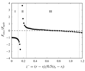
One way to assess the contributions of different forces to the balance of the MMB- $\unicode[STIX]{x1D719}$ (2.6b) is by plotting the ratio of two forces (Wei et al. Reference Wei, Fife, Klewicki and McMurtry2005; Klewicki et al. Reference Klewicki, Fife, Wei and McMurtry2007; Wei Reference Wei2018, Reference Wei2019). The ratio between the viscous force and the turbulent force
 $F_{visc}/F_{turb}$ in a TCF is shown in figure 7(a). For comparison, the force ratio
 $F_{visc}/F_{turb}$ in a pressure-driven turbulent channel flow is shown figure 7(b).
(a) Ratio between the viscous force and Reynolds shear force  $F_{visc}/F_{turb}$ in the MMB-
 $\unicode[STIX]{x1D719}$ (2.6b) for a TCF. Data are from DNS of Tanaka et al. (Reference Tanaka, Kawata and Tsukahara2018) for
 $r_{i}/r_{o}=0.5$ (
 $A_{t}=0.33$) and
 $(r_{o}-r_{i})r_{i}|\unicode[STIX]{x1D6FA}_{i}|/\unicode[STIX]{x1D708}=500$ and
 $4000$. (b) Ratio of
 $F_{visc}/F_{turb}$ in a pressure-driven plane channel flow. Here
 $z$ is the wall-normal distance, and
 $\unicode[STIX]{x1D6FF}$ is the channel half-width. Data are from DNS by Kawamura’s group (Kawamura et al. Reference Kawamura, Abe and Shingai2000; Shingai et al. Reference Shingai, Kawamura, Matsuo and Dopazo2000; Tsukahara et al. Reference Tsukahara, Kawamura and Shingai2006).

In a pressure-driven turbulent channel flow, the Reynolds shear force is zero near the channel wall, where the force balance is between the pressure force and the viscous force. Thus, the force ratio  $F_{visc}/F_{turb}$ in a turbulent channel flow starts from a large negative value at the channel wall. In a turbulent TCF, the turbulent Coriolis force is zero near the inner cylinder, where the force balance is between the viscous force and Reynolds shear force. Thus, the force ratio
 $F_{visc}/F_{turb}$ in a turbulent TCF is
 $-1$ at the inner cylinder. At sufficiently high Reynolds numbers, the inner half of a TCF exhibits a structure similar to that in the lower or upper half of a turbulent channel flow. The flow structure in a turbulent channel flow is symmetric about the channel centreline, but the flow structure in a TCF is not symmetric, because the friction velocity at the inner cylinder is different from that at the outer cylinder.
Based on the characteristics of the force ratio presented in figure 7, the inner half of a turbulent TCF can be divided into at least three layers:
(i) Layer I, an inner layer where the force balance is between the viscous force and the Reynolds shear force:
$|F_{visc}|\approx |F_{turb}|$.(ii) Layer II, a meso layer centred around the peak Reynolds shear stress location.
(iii) Layer III, an outer layer where the viscous force is negligible and the force balance is between the Reynolds shear force and the turbulent Coriolis force:
$|F_{cori}|\approx |F_{turb}|$.


The three-layer structure for the inner half of a turbulent TCF is sketched in figure 8.
Sketch of the layer structure in the inner half of a turbulent TCF. The data points are from DNS of Tanaka et al. (Reference Tanaka, Kawata and Tsukahara2018) for  $\mathit{Re}_{i}=4000$ and
 $A_{t}=0.333$ (
 $\mathit{Re}_{\unicode[STIX]{x1D70F},i}=164.6$).

We note that the DNS data used in this work are limited to relatively moderate Reynolds number. In particular, the friction Reynolds number for the outer half of a TCF,  $Re_{\unicode[STIX]{x1D70F},o}=\unicode[STIX]{x1D6FF}u_{\unicode[STIX]{x1D70F},o}/\unicode[STIX]{x1D708}$, is small. Thus, for the two cases shown in figure 7(a) the friction Reynolds numbers for the outer half are
 $Re_{\unicode[STIX]{x1D70F},o}=16.5$, and
 $82.5$. In the DNS of Tanaka et al. (Reference Tanaka, Kawata and Tsukahara2018), the lowest Reynolds number case,
 $Re_{\unicode[STIX]{x1D70F},i}=33$ and
 $Re_{\unicode[STIX]{x1D70F},o}=16.5$, has not achieved a fully developed turbulent state yet, and the flow in the outer half is more laminar like. For their highest Reynolds number case of
 $Re_{\unicode[STIX]{x1D70F},i}=165$ and
 $Re_{\unicode[STIX]{x1D70F},o}=82.5$, the inner half displays a well-established three-layer structure, but the layer structure of the outer half is very different.
The thickness of Layers I, II and III will depend on the Reynolds number, the geometry Atwood number and likely the rotation ratio  $\unicode[STIX]{x1D6F1}_{\unicode[STIX]{x1D6FA}}$. More DNS data are required to determine the thickness and the dependencies on the controlling non-dimensional numbers.
3.2 Scaling for Layer $\text{III}$ of the inner half

In the outer Layer III shown in figure 8, a natural length scale for the spatial variation in the radial direction  $\text{d}r$ is the gap half-width,
 $l_{ref}=\unicode[STIX]{x1D6FF}$. A reasonable length scale for the radial location is the mid-gap location
 $r_{ref}=r_{ctr}=0.5(r_{i}+r_{o})$. The friction velocity
 $u_{\unicode[STIX]{x1D70F},i}$ is used as a reference velocity scale
 $U_{\unicode[STIX]{x1D719},ref}=u_{\unicode[STIX]{x1D70F},i}$, as in pressure- or shear-driven turbulent wall-bounded flows. The Reynolds shear stress at the TCF mid-gap is used as a reference scale for the Reynolds shear stress
 $R_{r\unicode[STIX]{x1D719},ref}=|R_{r\unicode[STIX]{x1D719}}|_{ctr}$. The scaled variables for Layer III are denoted as follows
 $$\begin{eqnarray}z^{-}\stackrel{\text{def}}{=}{\displaystyle \frac{r-r_{_{i}}}{\unicode[STIX]{x1D6FF}}};\quad \text{d}z^{-}\stackrel{\text{def}}{=}{\displaystyle \frac{\text{d}r}{\unicode[STIX]{x1D6FF}}};\quad r^{\ast }\stackrel{\text{def}}{=}{\displaystyle \frac{r}{r_{ctr}}};\quad U_{\unicode[STIX]{x1D719}}^{+}\stackrel{\text{def}}{=}{\displaystyle \frac{U_{\unicode[STIX]{x1D719}}}{u_{\unicode[STIX]{x1D70F},i}}};\quad R_{r\unicode[STIX]{x1D719}}^{\ast }\stackrel{\text{def}}{=}{\displaystyle \frac{R_{r\unicode[STIX]{x1D719}}}{|R_{r\unicode[STIX]{x1D719}}|_{ctr}}}.\end{eqnarray}$$
Substituting the outer-scaled variables into (3.3), the outer-scaled MMB- $\unicode[STIX]{x1D719}$ equation can be presented as
 $$\begin{eqnarray}0=\left[{\displaystyle \frac{u_{\unicode[STIX]{x1D70F},i}^{2}}{|R_{r\unicode[STIX]{x1D719}}|_{ctr}}}{\displaystyle \frac{1}{\mathit{Re}_{\unicode[STIX]{x1D70F},i}}}\right]{\displaystyle \frac{\text{d}}{\text{d}z^{-}}}\left({\displaystyle \frac{1}{r^{\ast }}}{\displaystyle \frac{\text{d}}{\text{d}z^{-}}}(r^{\ast }U_{\unicode[STIX]{x1D719}}^{+})\right)+{\displaystyle \frac{\text{d}R_{r\unicode[STIX]{x1D719}}^{\ast }}{\text{d}z^{-}}}+A_{t}{\displaystyle \frac{2R_{r\unicode[STIX]{x1D719}}^{\ast }}{r^{\ast }}}.\end{eqnarray}$$
For a small gap with  $r_{i}\approx r_{o}$ or
 $A_{t}\approx 0$,
 $|R_{r\unicode[STIX]{x1D719}}|_{ctr}\approx u_{\unicode[STIX]{x1D70F},i}^{2}$ as shown above. Hence, a proper outer scaling for a turbulent TCF at small geometry Atwood number is
 $$\begin{eqnarray}0=\left[{\displaystyle \frac{1}{\mathit{Re}_{\unicode[STIX]{x1D70F},i}}}\right]{\displaystyle \frac{\text{d}}{\text{d}z^{-}}}\left({\displaystyle \frac{1}{r^{\ast }}}{\displaystyle \frac{\text{d}}{\text{d}z^{-}}}(r^{\ast }U_{\unicode[STIX]{x1D719}}^{+})\right)+{\displaystyle \frac{\text{d}R_{r\unicode[STIX]{x1D719}}^{+}}{\text{d}z^{-}}}+A_{t}{\displaystyle \frac{2R_{r\unicode[STIX]{x1D719}}^{+}}{r^{\ast }}}.\end{eqnarray}$$
This outer-scaled MMB- $\unicode[STIX]{x1D719}$ equation involves two non-dimensional numbers:
 $A_{t}$ and a friction Reynolds number
 $Re_{\unicode[STIX]{x1D70F},i}=\unicode[STIX]{x1D6FF}u_{\unicode[STIX]{x1D70F},i}/\unicode[STIX]{x1D708}$. An advantage of using
 $u_{\unicode[STIX]{x1D70F},i}^{2}$ instead of
 $|R_{r\unicode[STIX]{x1D719}}|_{ctr}$, from a practical perspective, is that
 $u_{\unicode[STIX]{x1D70F},i}$ can be directly obtained from the measurement of the mean torque at either the inner cylinder or the outer cylinder. Based on dimensional analysis,
 $|R_{r\unicode[STIX]{x1D719}}|_{ctr}$ is a function of
 $A_{t}$ and
 $Re_{\unicode[STIX]{x1D70F},i}$ and
 $\unicode[STIX]{x1D6F1}_{\unicode[STIX]{x1D6FA}}$. Therefore, for simplicity,
 $u_{\unicode[STIX]{x1D70F},i}^{2}$ will be used as a reference scale for the Reynolds shear stress, even when
 $|R_{r\unicode[STIX]{x1D719}}|_{ctr}$ is much smaller than
 $u_{\unicode[STIX]{x1D70F},i}^{2}$, when
 $A_{t}$ is not small.
Mean azimuthal velocity in outer scaling. Data are from DNS of Dong (Reference Dong2008) with  $A_{t}=1/3$. (a)
 $U_{\unicode[STIX]{x1D719}}^{+}$ versus
 $z^{-}$. (b)
 $r^{\ast }U_{\unicode[STIX]{x1D719}}^{+}$ versus
 $z^{-}$. PCF data are from DNS of Kawamura et al. (Reference Kawamura, Abe and Shingai2000) at
 $Re_{\unicode[STIX]{x1D70F}}=181$. PPF data are from Moser, Kim & Mansour (Reference Moser, Kim and Mansour1999) at
 $Re_{\unicode[STIX]{x1D70F}}=180$.

Figure 9 presents the DNS data of the mean azimuthal velocity for the same  $A_{t}$ and
 $\unicode[STIX]{x1D6F1}_{\unicode[STIX]{x1D6FA}}$, but different Reynolds numbers. In figure 9(a), the DNS data are presented as the inner-scaled mean azimuthal velocity
 $U_{\unicode[STIX]{x1D719}}^{+}$ versus the outer-scaled wall-normal distance
 $z^{-}$. In figure 9(b), the DNS data are presented as the normalized angular momentum
 $r^{\ast }U_{\unicode[STIX]{x1D719}}^{+}$ versus the outer-scaled wall-normal distance
 $z^{-}$. Figure 9 shows that the data at
 $Re_{\unicode[STIX]{x1D70F},i}=33$ deviate from the higher Reynolds number data. This deviation is the low Reynolds number effect, as in canonical turbulent channel or pipe flows (Tennekes & Lumley Reference Tennekes and Lumley1972).
In a turbulent plane Couette flow or a turbulent plane Poiseuille flow, the coordinate system is typically set up so the mean velocity at the wall is  $0$ and the scaling of the mean velocity for the outer layer is usually the so-called mean velocity deficit:
 $U_{ctr}-U$. In a TCF, the mean azimuthal velocity at the inner cylinder is usually set as
 $U_{\unicode[STIX]{x1D719},i}=r_{i}\unicode[STIX]{x1D6FA}_{i}$. Hence, the profile of
 $U_{\unicode[STIX]{x1D719}}$ in a TCF is analogous to the mean velocity deficit in a plane Couette flow. For comparison, the mean velocity deficit
 $U_{ctr}^{+}-U^{+}$ for a pressure-driven turbulent channel flow and a turbulent plane Couette flow are also presented in figure 9.
In figure 9, the mean velocity deficits for PCF and PPF are multiplied by an empirical factor of  $1/3$, to demonstrate the similar trend between TCF and PCF or PPF. The multiplying factor is related to the pre-factor in the viscous force term in (3.5):
 $u_{\unicode[STIX]{x1D70F},i}^{2}/|R_{r\unicode[STIX]{x1D719}}|_{ctr}\approx 1/(1-A_{t})^{2}\geqslant 1$. Compared with PCF or PPF, the core region of a turbulent TCF is better mixed and the mean velocity gradient is smaller. For a small Atwood number
 $A_{t}\rightarrow 0$, the mean azimuthal velocity in a turbulent TCF will approach the mean velocity deficit in a turbulent plane Couette flow.
In a pressure-driven turbulent channel flow, the mean velocity is symmetric about the channel centreline. In a shear-driven turbulent plane Couette flow, on the other hand, the mean velocity is anti-symmetric about the channel centreline. In either case, the mean velocity deficit will be exactly zero at the channel centreline  $z^{-}=1$. Notably, in a turbulent TCF, the mean flow is not anti-symmetric about the mid-gap. As shown in figure 9,
 $U_{\unicode[STIX]{x1D719}}$ in general is not zero at
 $z^{-}=1$.
In pressure- or shear-driven turbulent wall-bounded flows, the Reynolds shear stress profiles from different Reynolds numbers collapse well (see Pope Reference Pope2001), and as shown in figure 2,  $R_{r\unicode[STIX]{x1D719}}^{+}$ from different Reynolds numbers also collapse reasonably well versus
 $z^{-}$ for a turbulent TCF. The outer layer scaling for a turbulent TCF and pressure- or shear-driven turbulent wall-bounded flows are similar.
3.3 Scaling for Layer I of the inner half
In Layer I of the inner half shown in figure 8, the force balance is between the viscous force and the Reynolds shear force, similar to the inner layer in a pressure-driven turbulent channel or pipe flow. The mean azimuthal velocity will be scaled by  $u_{\unicode[STIX]{x1D70F},i}$, and the Reynolds shear stress will also be scaled by
 $u_{\unicode[STIX]{x1D70F},i}^{2}$. The distance from the wall
 $z=r-r_{i}$ will be scaled by the viscous length scale
 $\unicode[STIX]{x1D708}/u_{\unicode[STIX]{x1D70F},i}$. The inner scaled variables are denoted as
 $$\begin{eqnarray}z=r-r_{i};\quad \text{d}z^{+}\stackrel{\text{def}}{=}{\displaystyle \frac{\text{d}r}{\unicode[STIX]{x1D708}/u_{\unicode[STIX]{x1D70F},i}}};\quad U_{\unicode[STIX]{x1D719}}^{+}\stackrel{\text{def}}{=}{\displaystyle \frac{U_{\unicode[STIX]{x1D719}}}{u_{\unicode[STIX]{x1D70F},i}}};\quad R_{r\unicode[STIX]{x1D719}}^{+}\stackrel{\text{def}}{=}{\displaystyle \frac{R_{r\unicode[STIX]{x1D719}}}{u_{\unicode[STIX]{x1D70F},i}^{2}}};\quad r^{\ast }\stackrel{\text{def}}{=}{\displaystyle \frac{r}{r_{ctr}}}.\end{eqnarray}$$
Substituting the inner-scaled variables into (3.3), the inner-scaled MMB- $\unicode[STIX]{x1D719}$ equation can be expressed as
 $$\begin{eqnarray}0={\displaystyle \frac{\text{d}}{\text{d}z^{+}}}\left({\displaystyle \frac{1}{r^{\ast }}}{\displaystyle \frac{\text{d}}{\text{d}z^{+}}}(r^{\ast }U_{\unicode[STIX]{x1D719}}^{+})\right)+{\displaystyle \frac{\text{d}R_{r\unicode[STIX]{x1D719}}^{+}}{\text{d}z^{+}}}+{\displaystyle \frac{A_{t}}{\mathit{Re}_{\unicode[STIX]{x1D70F},i}}}{\displaystyle \frac{2R_{r\unicode[STIX]{x1D719}}^{+}}{r^{\ast }}}.\end{eqnarray}$$
The inner-scaled mean azimuthal velocity profiles are presented in figure 10(a). The data are presented as the difference between the mean azimuthal velocity and the inner cylinder velocity (the data are from the DNS of Dong (Reference Dong2008) for four Reynolds numbers). For comparison, the mean streamwise velocity in a turbulent plane Poiseuille flow and a turbulent plane Couette flow are also presented. As Reynolds number increases, the mean velocity  $U^{+}$ in PPF or PCF exhibits a layer with a logarithmic-like growth. The so-called log layer extends outwards as the Reynolds number increases. The mean relative velocity
 $U_{\unicode[STIX]{x1D719},i}^{+}-U_{\unicode[STIX]{x1D719}}^{+}$ in a turbulent TCF also exhibits a logarithmic-like growth away from the inner cylinder, but the additive constant in the logarithmic function varies with the Reynolds number, as shown in figure 10(a).
In figure 10(b), the relative angular momentum is plotted as the form in (3.8). DNS data from different Reynolds numbers but the same  $A_{t}$ are seen to collapse reasonably well in the inner region. The relative angular momentum
 $r^{\ast }(U_{\unicode[STIX]{x1D719},i}^{+}-U_{\unicode[STIX]{x1D719}}^{+})$, for
 $A_{t}=1/3$, is below the mean velocity profile in a turbulent PPF or PCF. At the small-gap limit or
 $A_{t}\rightarrow 0$, the relative angular momentum
 $r^{\ast }(U_{\unicode[STIX]{x1D719},i}^{+}-U_{\unicode[STIX]{x1D719}}^{+})$ in a turbulent TCF will approach the mean velocity distribution of a turbulent channel or Couette flow. On the other hand, for the large-gap limit, the relative angular momentum will become even smaller, as indicated by the arrow for
 $A_{t}$. For a fixed
 $A_{t}$, the relative angular momentum also exhibits a layer with a logarithmic-like growth, and this log layer extends outwards as the Reynolds number increases, indicated by the arrow for
 $\mathit{Re}$. More DNS simulations are required to study the effect of Atwood number, Reynolds number and rotation ratio.
Scaling of the mean azimuthal velocity for Layer I of inner half. (a) Inner-scaled mean azimuthal velocity relative to the inner cylinder velocity versus the inner-scaled wall-normal distance  $z^{+}$. (b) Inner-scaled mean angular momentum versus
 $z^{+}$. Data are from DNS of Dong (Reference Dong2008) for
 $A_{t}=1/3$. For comparison, DNS data of turbulent plane Couette flow at
 $Re_{\unicode[STIX]{x1D70F}}=181$ by Kawamura et al. (Reference Kawamura, Abe and Shingai2000), and DNS data of turbulent channel flow at two Reynolds numbers
 $Re_{\unicode[STIX]{x1D70F}}=180$ and
 $590$ by Moser et al. (Reference Moser, Kim and Mansour1999) are also plotted.

Note that the boundary condition at the inner cylinder wall can be presented as
 $$\begin{eqnarray}\left|{\displaystyle \frac{\text{d}U_{\unicode[STIX]{x1D719}}^{+}}{\text{d}z^{+}}}\right|_{r=r_{i}}-{\displaystyle \frac{U_{\unicode[STIX]{x1D719}}^{+}|_{r=r_{i}}}{\left({\displaystyle \frac{1}{A_{t}}}-1\right)Re_{\unicode[STIX]{x1D70F},i}}}\bigg|=1.\end{eqnarray}$$
If  $U_{\unicode[STIX]{x1D719}}^{+}|_{r=r_{i}}=0$ (inner cylinder fixed, outer cylinder rotating), the inner-scaled mean azimuthal velocity gradient is
 $1$, similar to that in a turbulent channel or Couette flow. However, if the inner cylinder is not fixed, the inner-scaled mean azimuthal velocity gradient at the wall will be smaller than
 $1$. The difference is minor for small Atwood numbers and/or high Reynolds numbers. This explains why the TCF data in figure 10(a) are slightly below the curve of
 $U^{+}=z^{+}$ (dashed curve in the figure).
DNS data for the inner scaling of the Reynolds shear stress are presented in figure 11. For the same  $A_{t}$ and rotation ratio, the inner-scaled Reynolds shear stress profiles from different Reynolds numbers collapse reasonable well in the inner layer. For comparison, the Reynolds shear stress for a turbulent channel flow at
 $Re_{\unicode[STIX]{x1D70F}}=180$ is shown in figure 11(a). The inner-scaled Reynolds shear stress in a turbulent TCF displays a trend in Layer I that is similar to the Layer I of a pressure-driven turbulent channel flow.
In figure 11(b), the DNS data of  $-(r/r_{i})^{2}R_{r\unicode[STIX]{x1D719}}^{+}$ in a TCF are plotted, along with the Reynolds shear stress for a turbulent plane Couette flow at
 $Re_{\unicode[STIX]{x1D70F}}=181$. The inner-scaled Reynolds shear stress data for TCF at different Reynolds numbers collapse reasonably well. The deviation at
 $Re_{\unicode[STIX]{x1D70F},i}=33$ is caused by the low Reynolds number effect.
Scaling of the Reynolds shear stress for the inner layer. (a)  $-R_{r\unicode[STIX]{x1D719}}^{+}$ versus
 $z^{+}$. The TCF data are from DNS of Dong (Reference Dong2008) with counter-rotating cylinder and
 $A_{t}=0.333$. The turbulent plane channel flow data are from DNS of Moser et al. (Reference Moser, Kim and Mansour1999) at
 $\mathit{Re}_{\unicode[STIX]{x1D70F}}=180$. (b)
 $-(r/r_{i})^{2}R_{r\unicode[STIX]{x1D719}}^{+}$ versus
 $z^{+}$. The turbulent plane Couette data are from DNS of Kawamura et al. (Reference Kawamura, Abe and Shingai2000) at
 $Re_{\unicode[STIX]{x1D70F}}=181$.

4 Discussion
In a plane Couette flow, there is only one controlling non-dimensional number:  $Re_{\unicode[STIX]{x1D70F}}$. In contrast, there are four controlling parameters in a turbulent TCF:
 $\unicode[STIX]{x1D6E4}$,
 $\unicode[STIX]{x1D6F1}_{\unicode[STIX]{x1D6FA}}$,
 $A_{t}$ and
 $Re_{\unicode[STIX]{x1D70F},i}$. For sufficiently long cylinders (
 $\unicode[STIX]{x1D6E4}\gg 10$), the flow is statistically homogeneous in the axial direction. Experimental and numerical simulation data show that the peak Reynolds shear stress location and value are strongly influenced by
 $A_{t}$ and
 $Re_{\unicode[STIX]{x1D70F},i}$. The effect of
 $\unicode[STIX]{x1D6F1}_{\unicode[STIX]{x1D6FA}}$ on the location and value of peak Reynolds shear stress remains to be investigated.
In the inner half of a turbulent TCF, Reynolds shear stress rises sharply from zero to a peak value, then decreases gradually to zero at the outer cylinder. In comparison, in a pressure-driven turbulent channel flow, Reynolds shear stress rises sharply from zero at the wall and decreases almost linearly to zero at the channel centreline (Tennekes & Lumley Reference Tennekes and Lumley1972). The similarities and differences between a turbulent channel flow and a turbulent TCF can be explained by the mean momentum balance equation in the streamwise direction for the two flows
 $$\begin{eqnarray}\displaystyle & \displaystyle 0=\underbrace{{\displaystyle \frac{\text{d}^{2}U^{+}}{\text{d}z^{+2}}}}_{F_{visc}}+\underbrace{{\displaystyle \frac{\text{d}R_{wu}^{+}}{\text{d}z^{+}}}}_{F_{turb}}+\underbrace{{\displaystyle \frac{1}{Re_{\unicode[STIX]{x1D70F}}}}}_{F_{pres}}.\quad \text{Turbulent Channel Flow} & \displaystyle\end{eqnarray}$$
 $$\begin{eqnarray}\displaystyle & \displaystyle 0=\underbrace{{\displaystyle \frac{\text{d}}{\text{d}z^{+}}}\left({\displaystyle \frac{1}{r^{\ast }}}{\displaystyle \frac{\text{d}}{\text{d}z^{+}}}(r^{\ast }U_{\unicode[STIX]{x1D719}}^{+})\right)}_{F_{visc}}+\underbrace{{\displaystyle \frac{\text{d}R_{r\unicode[STIX]{x1D719}}^{+}}{\text{d}z^{+}}}}_{F_{turb}}+\underbrace{{\displaystyle \frac{A_{t}}{\mathit{Re}_{\unicode[STIX]{x1D70F},i}}}{\displaystyle \frac{2R_{r\unicode[STIX]{x1D719}}^{+}}{r^{\ast }}}}_{F_{cori}}.\quad \text{Turbulent TCF} & \displaystyle\end{eqnarray}$$
 $x$ is the streamwise direction, and
 $z$ is the wall-normal direction;
 $U^{+}=U/u_{\unicode[STIX]{x1D70F}}$ denotes the mean streamwise velocity normalized by the friction velocity,
 $R_{wu}^{+}=-\langle wu\rangle /u_{\unicode[STIX]{x1D70F}}^{2}$ is the kinematic Reynolds shear stress normalized by the square of the friction velocity and the last term comes from the mean pressure force (see Tennekes & Lumley Reference Tennekes and Lumley1972; Pope Reference Pope2001).
In the outer layer of a turbulent TCF, the turbulent Coriolis force  $F_{cori}=2R_{r\unicode[STIX]{x1D719}}/r$ is a driving force of the flow (see figure 6), similar to the mean pressure gradient
 $-\text{d}(P/\unicode[STIX]{x1D70C})/\text{d}x=u_{\unicode[STIX]{x1D70F}}^{2}/\unicode[STIX]{x1D6FF}$ in a turbulent channel flow. In a turbulent channel flow, the pressure force is a constant, but in a turbulent TCF,
 $F_{cori}$ is not a constant (see figure 6).
It is observed that in a pressure- or shear-driven turbulent wall-bounded flow, flow transitions to a turbulent state if the friction Reynolds number  $Re_{\unicode[STIX]{x1D70F}}=\unicode[STIX]{x1D6FF}u_{\unicode[STIX]{x1D70F}}/\unicode[STIX]{x1D708}\gtrsim O(100)$. In a TCF, on the other hand, the friction Reynolds number for the inner half
 $Re_{\unicode[STIX]{x1D70F},i}=\unicode[STIX]{x1D6FF}u_{\unicode[STIX]{x1D70F},i}/\unicode[STIX]{x1D708}$ is always larger than for the outer half
 $Re_{\unicode[STIX]{x1D70F},o}=\unicode[STIX]{x1D6FF}u_{\unicode[STIX]{x1D70F},o}/\unicode[STIX]{x1D708}$, regardless of the rotation ratio
 $\unicode[STIX]{x1D6F1}_{\unicode[STIX]{x1D6FA}}$, because
 $u_{\unicode[STIX]{x1D70F},o}/u_{\unicode[STIX]{x1D70F},i}=(r_{i}/r_{o})=(1-A_{t})/(1+A_{t})$. In a turbulent channel or Couette flow, the channel half-width is typically used as the height of the boundary layer, but flow in a turbulent TCF is not symmetric about the mid-gap, and the border between the inner part and the outer part is not known a priori.
For a turbulent TCF with a small Atwood number,  $Re_{\unicode[STIX]{x1D70F},i}$ is not much larger than
 $Re_{\unicode[STIX]{x1D70F},o}$, but at a large Atwood number, the friction Reynolds numbers can be very different. For example, for
 $Re_{\unicode[STIX]{x1D70F},i}=1000$, a relatively large Reynolds number, the friction Reynolds number for the outer half will be
 $Re_{\unicode[STIX]{x1D70F},o}=52.6$ for
 $A_{t}=0.9$ and
 $Re_{\unicode[STIX]{x1D70F},o}=5$ for
 $A_{t}=0.99$. It is reasonable to speculate that for this case the inner part will be highly turbulent, but the outer part cannot sustain a turbulent state and will remain a laminar-like state.
If  $Re_{\unicode[STIX]{x1D70F},o}$ is sufficiently high, the scaling of the mean momentum balance equation and the flow structure in the outer half of a TCF gap will be similar to that of the inner half. More specifically, the Reynolds shear stress will have a peak next to the outer cylinder. This peak Reynolds shear stress location will be the centre of a meso-layer (Layer II) for the outer half. The Reynolds shear stress peak near the outer cylinder will be smaller than that near the inner cylinder, and the peak location and peak value depend on the Reynolds number, the geometry Atwood number and perhaps also the rotation ratio as well.
The effect of the rotation ratio  $\unicode[STIX]{x1D6F1}_{\unicode[STIX]{x1D6FA}}$ on the layer structure and multiscaling analysis of the mean momentum balance equation is not clear at this stage. However, the rotation ratio
 $\unicode[STIX]{x1D6F1}_{\unicode[STIX]{x1D6FA}}$ appears only in the boundary conditions, and is not directly involved in the mean momentum balance equation.
Analysing a Nusselt-style non-dimensional angular velocity flux  $Nu_{\unicode[STIX]{x1D714}}$, Van Gils et al. (Reference Van Gils, Huisman, Grossmann, Sun and Lohse2012) found that the angular velocity transfer is affected by the cylinder rotation ratio. For a gap with
 $\unicode[STIX]{x1D6F1}_{r}=0.716$ or
 $A_{t}=0.165$, Van Gils et al. (Reference Van Gils, Huisman, Grossmann, Sun and Lohse2012) observed a very pronounced maximum of
 $Nu_{\unicode[STIX]{x1D714}}$ at
 $\unicode[STIX]{x1D6F1}_{\unicode[STIX]{x1D6FA}}\approx -3$, indicating an optimal angular velocity transport from the inner to the outer cylinder at that angular velocity ratio. The optimal number was refined by Huisman et al. (Reference Huisman, Van D Veen, Sun and Lohse2014) to be
 $\unicode[STIX]{x1D6F1}_{\unicode[STIX]{x1D6FA}}=-2.78$. Ostilla-Mónico et al. (Reference Ostilla-Mónico, Huisman, Jannink, Van Gils, Verzicco, Grossmann, Sun and Lohse2014) investigated the effect of radius ratio on the optimal Taylor–Couette flow, and defined two regimes: a co- and weakly counter-rotating regime, and a strongly counter-rotating regime. Grossmann et al. (Reference Grossmann, Lohse and Sun2016) have shown that the angular velocity profile and flow structures in the bulk of a TCF are strongly influenced by the rotation ratio. As an issue for future research on TCF, they pointed out that a rigorous theoretical understanding of the dependence of an optimal rotation ratio and the gap radius ratio is still missing.
Due to the limitations on the available DNS data on TCF with different  $\unicode[STIX]{x1D6F1}_{\unicode[STIX]{x1D6FA}}$, the effect of the rotation ratio on the layer structure is not explored in the present work. It will be very interesting to study the effect of
 $\unicode[STIX]{x1D6F1}_{\unicode[STIX]{x1D6FA}}$ on the distribution of the mean azimuthal velocity
 $U_{\unicode[STIX]{x1D719}}$ and the angular momentum
 $rU_{\unicode[STIX]{x1D719}}$. It will also be very interesting to study the effect of
 $\unicode[STIX]{x1D6F1}_{\unicode[STIX]{x1D6FA}}$ on the distribution of the Reynolds shear stress
 $R_{r\unicode[STIX]{x1D719}}$ and the turbulent Coriolis force
 $2R_{r\unicode[STIX]{x1D719}}/r$. Systematic DNS studies are required. For a TCF with fixed
 $A_{t}$, one could perform a series of simulations at the same
 $Re_{\unicode[STIX]{x1D70F},i}$ but with different
 $\unicode[STIX]{x1D6F1}_{\unicode[STIX]{x1D6FA}}$, covering both co-rotating and counter-rotating conditions.
5 Summary
The present work investigated the properties of the mean momentum balance equation for a fully turbulent TCF, and in particular the MMB equation in the azimuthal  $\unicode[STIX]{x1D719}$ direction. The integrated MMB-
 $\unicode[STIX]{x1D719}$ equation confirms that the sum of the moment (or torque) from the viscous shear stress and the Reynolds shear stress is a constant, as was first found by Townsend (Reference Townsend1980) and Eckhardt et al. (Reference Eckhardt, Grossmann and Lohse2007). At a sufficiently high Reynolds number, the viscous shear stress is negligible in the core of a turbulent TCF, and the Reynolds shear stress can be approximated as
 $|R_{r\unicode[STIX]{x1D719}}|\approx (r_{i}/r)^{2}u_{\unicode[STIX]{x1D70F},i}^{2}$. It is found that the peak Reynolds shear stress location always occurs near the inner cylinder, and it is strongly influenced by the geometry Atwood number
 $A_{t}$ and the Reynolds number. The peak Reynolds shear stress location moves closer to the inner cylinder with increasing
 $A_{t}$, and also moves closer to the inner cylinder as the Reynolds number increases. For a fixed
 $A_{t}$, the dependence of the peak Reynolds shear stress location on the Reynolds number is very similar to that in a pressure-driven turbulent channel flow, that is, the peak Reynolds shear location is a meso length scale.
The MMB- $\unicode[STIX]{x1D719}$ equation is rearranged and integrated to obtain an analytical solution for the global integral of the turbulent Coriolis force. The analytical solution is verified by the DNS studies. It is found that the global integral of the turbulent Coriolis force depends on
 $A_{t}$,
 $\unicode[STIX]{x1D6F1}_{\unicode[STIX]{x1D6FA}}$,
 $Re_{\unicode[STIX]{x1D70F},i}$ and
 $U_{\unicode[STIX]{x1D719},i}^{+}$. At the small-gap limit (
 $A_{t}\rightarrow 0$), the global integral approaches zero
 $\int _{r_{i}}^{r_{o}}(2R_{r\unicode[STIX]{x1D719}}^{+}/r)\,\text{d}r\rightarrow 0$ or
 $\int _{r_{i}}^{r_{o}}(2R_{r\unicode[STIX]{x1D719}}/r)\,\text{d}r\rightarrow 0$. In other words, the turbulent TCF at the small-gap limit approaches the turbulent plane Couette flow. At the large-gap limit (
 $A_{t}\rightarrow 1$), the global integral approaches
 $\int _{r_{i}}^{r_{o}}(2R_{r\unicode[STIX]{x1D719}}^{+}/r)\,\text{d}r\rightarrow -1$ or
 $\int _{r_{i}}^{r_{o}}(2R_{r\unicode[STIX]{x1D719}}/r)\,\text{d}r\rightarrow -u_{\unicode[STIX]{x1D70F},i}^{2}$. At high Reynolds numbers, the global integral of the turbulent Coriolis force is only weakly influenced by the rotation ratio
 $\unicode[STIX]{x1D6F1}_{\unicode[STIX]{x1D6FA}}$. The effect of the rotation ratio
 $\unicode[STIX]{x1D6F1}_{\unicode[STIX]{x1D6FA}}$ also becomes smaller for
 $A_{t}\rightarrow 0$.
A three-layer structure is proposed for the inner part of a turbulent TCF, based on the characteristics of force balance in the MMB- $\unicode[STIX]{x1D719}$ equation: an inner Layer I, a meso Layer II and an outer Layer III. In the inner layer, the force balance is between the viscous force and the Reynolds shear force. In the outer layer, the force balance is between the turbulent Coriolis force and the Reynolds shear force. In the meso-layer, all three forces contribute to the force balance. A three-layer structure will also emerge for the outer part of the TCF gap if
 $Re_{\unicode[STIX]{x1D70F},o}$ is sufficiently high.
The similarities and differences between a turbulent TCF and a pressure-driven turbulent channel flow are elucidated. The turbulent Coriolis force plays a role similar to that of the pressure force in a turbulent channel flow. However, the pressure force in a fully developed channel flow is a constant, but the turbulent Coriolis force in a turbulent TCF varies in the radial (or wall-normal) direction.
An outer scaling is developed for the outer layer in a fully developed turbulent TCF. In the outer layer, the TCF gap half-width  $\unicode[STIX]{x1D6FF}$ is proposed as a proper length scale for the spatial variation in the radial direction
 $\text{d}r$. A proper length scale for
 $r$ in the turbulent Coriolis force is the TCF mid-gap location
 $r_{ctr}=0.5(r_{i}+r_{o})$. The friction velocity
 $u_{\unicode[STIX]{x1D70F},i}$ is proposed as a velocity scale for the mean azimuthal velocity, and
 $u_{\unicode[STIX]{x1D70F},i}^{2}$ is proposed as a scale for the kinematic Reynolds shear stress. Two non-dimensional numbers emerge from the outer-scaled MMB-
 $\unicode[STIX]{x1D719}$ equation: a friction Reynolds number
 $Re_{\unicode[STIX]{x1D70F},i}$ and a geometry Atwood number
 $A_{t}$.
An inner scaling is developed for the inner Layer I of a fully developed turbulent TCF. In Layer I, the viscous length scale  $\unicode[STIX]{x1D708}/u_{\unicode[STIX]{x1D70F},i}$ is proposed as a length scale for the spatial variation in the radial direction
 $\text{d}r$. Friction velocity
 $u_{\unicode[STIX]{x1D70F},i}$ is used to scale the mean azimuthal velocity and the kinematic Reynolds shear stress.
The inner scaling and outer scaling for a turbulent TCF are similar to those in a pressure-driven turbulent channel flow, as summarized in table 3. The characteristic scales for length, velocity and Reynolds shear stress are also listed in table 3. The proposed inner scaling and outer scaling are verified against available DNS data of the mean azimuthal velocity  $U_{\unicode[STIX]{x1D719}}$ and Reynolds shear stress
 $R_{r\unicode[STIX]{x1D719}}$. The currently available DNS data are still limited in the parameter space of
 $A_{t}$,
 $\unicode[STIX]{x1D6F1}_{\unicode[STIX]{x1D6FA}}$ and
 $Re_{\unicode[STIX]{x1D70F},i}$, and in particular, the Reynolds number
 $Re_{\unicode[STIX]{x1D70F},o}$ is in general too small to establish a three-layer structure in the outer part. More DNS simulations are required to check the validity of the analysis.
TCFs are found in many and varied applications and fields of research. While experimental and theoretical work over the last century has offered considerable insights and data, many questions remain unanswered. The present paper demonstrates a methodology that is shown to be applicable to turbulent flow under different driving mechanisms and geometries. In specific, the present work proposed a three-layer structure, and inner and outer scalings, opening up a pathway for future work on the understanding of the underlying physics in a turbulent TCF.
Comparison of inner scaling and outer scaling for the mean momentum balance equation in the streamwise direction for a turbulent Taylor–Couette flow and a turbulent channel flow. For the turbulent channel flow,  $x$ is the streamwise direction and
 $z$ is the wall-normal direction.
 $U$ is the mean streamwise velocity, and
 $R_{wu}$ is the kinematic Reynolds shear stress. Mean pressure gradient is
 $-\text{d}(P/\unicode[STIX]{x1D70C})/\text{d}x=u_{\unicode[STIX]{x1D70F}}^{2}/\unicode[STIX]{x1D6FF}$ (see Tennekes & Lumley Reference Tennekes and Lumley1972; Pope Reference Pope2001).

Acknowledgements
The author is very grateful to Dr S. Dong and Dr T. Tsukahara for generously sharing their data.
Declaration of interests
The authors report no conflict of interest.
Appendix A. Geometry Atwood number
In studies of Rayleigh–Taylor instability (Glimm et al. Reference Glimm, Grove, Li, Oh and Sharp2001; Livescu et al. Reference Livescu, Ristorcelli, Gore, Dean, Cabot and Cook2009; Wei & Livescu Reference Wei and Livescu2012), an Atwood number is defined to characterize the density difference between two fluids
 $$\begin{eqnarray}A_{\unicode[STIX]{x1D70C}}\stackrel{\text{def}}{=}{\displaystyle \frac{\unicode[STIX]{x1D70C}_{heavy}-\unicode[STIX]{x1D70C}_{light}}{\unicode[STIX]{x1D70C}_{heavy}+\unicode[STIX]{x1D70C}_{light}}},\end{eqnarray}$$
where  $\unicode[STIX]{x1D70C}_{heavy}$ is the density of the heavy fluid, and
 $\unicode[STIX]{x1D70C}_{light}$ is the density of the light fluid;
 $A_{\unicode[STIX]{x1D70C}}$, bounded between
 $0$ and
 $1$, is found to be a very important parameter in the analysis of the Rayleigh–Taylor instability. In the present work,
 $A_{t}$ is a non-dimensional ratio of the cylinder radii, and is called the geometry Atwood number. Like the Atwood number in Rayleigh–Taylor instability, the geometry Atwood number is bounded between
 $0\leqslant A_{t}\leqslant 1$
 $$\begin{eqnarray}\displaystyle & \displaystyle A_{t}\rightarrow 0\quad \text{if }r_{i}\rightarrow r_{o}; & \displaystyle\end{eqnarray}$$
 $$\begin{eqnarray}\displaystyle & \displaystyle A_{t}\rightarrow 1\quad \text{if }r_{i}\ll r_{o}. & \displaystyle\end{eqnarray}$$
Appendix B. Viscous force in the MMB-$\unicode[STIX]{x1D719}$ equation

The viscous force term in (2.6b) can also be written in the following forms:
 $$\begin{eqnarray}\displaystyle F_{visc} & = & \displaystyle \unicode[STIX]{x1D708}{\displaystyle \frac{\text{d}}{\text{d}r}}\left({\displaystyle \frac{1}{r}}{\displaystyle \frac{\text{d}}{\text{d}r}}(rU_{\unicode[STIX]{x1D719}})\right)\end{eqnarray}$$
 $$\begin{eqnarray}\displaystyle & = & \displaystyle \unicode[STIX]{x1D708}{\displaystyle \frac{\text{d}}{\text{d}r}}\left({\displaystyle \frac{\text{d}U_{\unicode[STIX]{x1D719}}}{\text{d}r}}+{\displaystyle \frac{U_{\unicode[STIX]{x1D719}}}{r}}\right)\end{eqnarray}$$
 $$\begin{eqnarray}\displaystyle & = & \displaystyle {\displaystyle \frac{1}{r^{2}}}\unicode[STIX]{x1D708}{\displaystyle \frac{\text{d}}{\text{d}r}}\left(r^{2}\left({\displaystyle \frac{\text{d}U_{\unicode[STIX]{x1D719}}}{\text{d}r}}-{\displaystyle \frac{U_{\unicode[STIX]{x1D719}}}{r}}\right)\right).\end{eqnarray}$$
In (B 1a),  $rU_{\unicode[STIX]{x1D719}}$ is the angular momentum. In (B 1c),
 $\unicode[STIX]{x1D708}(\text{d}U_{\unicode[STIX]{x1D719}}/\text{d}r-U_{\unicode[STIX]{x1D719}}/r)$ is the viscous shear stress.



