1. INTRODUCTION
One of the most popular computational design synthesis approaches in engineering design involves topology optimization methods, which is based on using finite element methods for the analysis, and various gradient-based optimization techniques (Bendsøe & Sigmund, Reference Bendsøe and Sigmund2003). For more than two decades, engineering designers have used shape and topology optimization methods for a wide range of structural design problems. These optimization methods are now being used successfully by other areas such as electromagnetics, microelectromechanical, and fluids (Eschenauer & Olhoff, Reference Eschenauer and Olhoff2001; Bendsøe & Sigmund, Reference Bendsøe and Sigmund2003). Topology optimization is a mathematical approach that models a fixed number of decision variables (cells or grids) and optimizes its objective function (e.g., part stiffness) for a given set of boundary conditions and loads (Bendsøe & Sigmund, Reference Bendsøe and Sigmund2003). Numerical optimization methods have shown their efficiency in aiding the synthesis of engineering artifacts by generating many novel solutions (Bendsøe & Sigmund, Reference Bendsøe and Sigmund2003).
Borrvall and Petersson (Reference Borrvall and Petersson2003) were the first to use topology optimization for solving fluid problems in Stokes flow. Optimization of fluid channels is an essential topic in designing microfluidic devices (Okkels et al., Reference Okkels, Olesen and Bruus2005; Andreasen et al., Reference Andreasen, Gersborg and Sigmund2009; Vangelooven et al., Reference Vangelooven, De Malsche, Op De Beeck, Eghbali, Gardeniers and Desmet2010). It has application in diverse areas such as designing pipe bends for minimum head loss, diffusers, valves, interior air flow of vehicles, and engine intake ports. The goal is mainly to find an optimal topology for the fluid subdomains along with an optimal shape of channels that minimizes the power dissipated by the fluid (Liu et al., Reference Liu, Gao, Zhang, Xuan and Wu2010). In order to use Stokes equations, the fluid flow is mainly assumed to be incompressible, steady, and slow (inertia effects are neglected). Topology optimization has been applied to solve Stokes flow problems in large-scale flow (Aage et al., Reference Aage, Poulsen, Gersborg-Hansen and Sigmund2007), to design maximum permeability of material microstructures (Guest & Prévost, Reference Guest and Prévost2007), and in optimizing multifunctional materials (i.e., microstructures with maximum stiffness and fluid permeability; Guest & Prévost, Reference Guest and Prévost2006b). Using topology optimization methods in solving channel fluid layouts has received a large amount of attention from scientists in recent years, and various parameterizations have been suggested to solve Stokes flow (Guest & Prévost, Reference Guest and Prévost2006a) and Navier–Stokes flow problems (Evgrafov, Reference Evgrafov2006) with different Reynolds numbers (Gersborg-Hansen et al., Reference Gersborg-Hansen, Sigmund and Haber2005; Olesen et al., Reference Olesen, Okkels and Bruus2006; Duan et al., Reference Duan, Ma and Zhang2008; Zhou & Li, Reference Zhou and Li2008). Details of using different approaches such as level set or material distribution in solving fluid topology optimization problems and various techniques to increase the computational efficiency and the chance to find the global minimum can be found in the recent contribution of Challis and Guest (Reference Challis and Guest2009). They describe methods that can avoid convergence of the algorithm to local minima (Borrvall & Petersson, Reference Borrvall and Petersson2003; Aage et al., Reference Aage, Poulsen, Gersborg-Hansen and Sigmund2007; Guest & Prévost, Reference Guest and Prévost2006b) and aim to overcome limitations of other models such as Zhou and Li (Reference Zhou and Li2008) with costly computational power for remeshing the whole domain. The chronological progress of results in the literature reveals significant improvements concerning minimizing required time and computation power, achieving global minimums, smoothing the boundaries, and using various Reynolds values for the flow. However, even very recent results by different scientists in the field (Liu et al., Reference Liu, Gao, Zhang, Xuan and Wu2010; Challis & Guest, Reference Challis and Guest2009; Jang et al., Reference Jang, Panganiban and Chung2010) show that problems are mainly limited in complexity; number and direction of inlets and outlets, flow equation; mainly stokes flow, and number of fluid types; if combination of fluids is not allowed. They are mainly two-dimensional problems, and the time is still a challenge, especially for solving complex three-dimensional (3-D) problems. Challis and Guest (Reference Challis and Guest2009) have illustrated the required time for a variety of level set topology optimization of fluids in Stokes flow. Considering these limitations and demanding industrial problems in terms of complexity reveals a gap in capabilities and computational power of current models.
One of the major limitations, which topology optimization methods in conceptual design are facing, is limited representation power. The synthesis process and design rules are dependent and integrated into the simulation model; the simulation model is often fixed for a given set of loads and boundary conditions. The simulation model is based on time-consuming numerical approaches (depending upon the type of the simulation) and many design iterations are required; therefore, the convergence is too slow. The aim of this paper is to introduce a new perspective and show the abilities of generative design systems, such as graph grammars, in achieving more flexible design synthesis automation and optimization of fluid channels. The novelty of the proposed method is in the fact that an effective application of generative design synthesis methods along with conventional simulation models is proposed, leading to overcoming main limitations of the previous methods and significant reduction in the numerical costs.
This method uses a graph grammars interpreter to generate different topological solutions for the fluid channel problem. Through exhaustive search of the design space, all valid candidates are generated and evaluated initially. As the search process is carried out in the graph representation mode, the entire design space is searched within a few seconds; for problems with many inlets and outlets, the time can be increased to several minutes. Based on the evaluation results they are sorted in a list. Two optimization algorithms are used to optimize all or top candidates of the list. These optimization algorithms change the radius of fluid channels and the position of intermediate nodes, which has been added to the design, to minimize head loss. The candidates are again stored in a second list based on the objective function values. Finally, they are first transformed into meaningful 3-D shapes to be simulated in an adequate computational fluid dynamics (CFD) solver. The nodes and arcs of the generated graph represent constructive solid geometry (CSG) shapes. The graph grammars rules work with graph elements to generate a new topological state; therefore, the search and generation process is very fast. However, it is vitally important to embed enough information in the graph grammar rules in order to create precise 3-D shapes, which is the biggest challenge in using a graph to represent an eventual 3-D shape. To increase the computational effectiveness of the generation process, the design process is carried out in different steps. To enter each step, the candidate solution must meet specific requirements, such as maximum allowed compression of the fluid; otherwise, it will be filtered out. After passing the requirements of three such filters, information is added to the candidate solution. This mechanism prevents unnecessary processing of unrequired information in earlier stages. With the help of these mechanisms, it is possible to control the quality of candidates that are sent to the CFD solver for evaluation.
By utilizing a multiple representation approach for the topology optimization of channels, our algorithm avoids many problems associated with other approaches in setting up the fluid equations. There is no need for a parameterization scheme because representing the topology is independent of the simulation model. This eliminates the need for using Stokes flow in defining the topology and also postprocessing of the results, and it provides a more accurate control over designing of solution topologies. It causes significant computational savings, because the CFD analyses and remeshing at each iteration (of the simulation and optimization) is no longer required, which is a prohibitive for many models (Zhou & Li, Reference Zhou and Li2008). By using multiple representations in our method, dimension has almost no effect on the computation efforts in finding flow channel topologies that show the numerical efficiency of the proposed approach. However, after finding candidate design solutions, the transformation and CFD analysis of 3-D results are computationally more costly. Because the representation and simulation models are fully separated from each other, one can use the same rule sets for problems with completely different boundary conditions, fluid types, fluid directions, and loads.
The proposed method produces results in agreement with previously solved power dissipation minimization problems for Stokes flow (Borrvall & Petersson, Reference Borrvall and Petersson2003; Guest & Prévost, Reference Guest and Prévost2006b; Challis & Guest, Reference Challis and Guest2009; Liu et al., Reference Liu, Gao, Zhang, Xuan and Wu2010). The effectiveness of the proposed method is checked by solving a variety of available test problems and comparing them with those found in the literature, and the results of different complex problems with arbitrary flow directions in inlets and outlets shows high capabilities of the method in solving very complex large-scale 3-D problems.
This paper is organized as follows. Section 2 describes a background about generative design synthesis systems and our graph grammar approach. Section 3 provides details of the proposed approach in this paper. Section 4 presents achieved results and discusses the implications of results; the focus of this section is to present significant benefits of proposed methodology over previously used approaches. Finally, Section 5 concludes the study and suggests further research projects to extend the presented work.
2. BACKGROUND
2.1. Generative design synthesis systems
Due to the complexity of design problems to solve (Lewis et al., Reference Lewis, Weir, Field, Culley, Duffy, McMahon and Wallace2001), which in turn comes from lack of knowledge about ill-structured design problems (Simon, Reference Simon1973), a better understanding and a formal representation of the cognitive processes during different phases of design evolution are necessary to realize automated creative design (Alber & Rudolph, Reference Alber, Rudolph, Borg, Farrugia and Camilleri2004). In addition, to reach a high level of creativity, it is essential to go beyond the restrictions of already existing solutions and frames of reference (Akin & Akin, Reference Akin and Akin1998) and extend the boundaries of the design search space. “Generative design systems are aimed at creating new design processes that produce spatially novel yet efficient and buildable designs through exploitation of current computing and manufacturing capabilities” (Shea et al., Reference Shea, Aish and Gourtovaia2003). Synthesis methods aim to assist designers in the creative phase of the design process and generate solutions that are novel and beyond a designer's own insight (Bolognini et al., Reference Bolognini, Shea, Vale and Seshia2006).
Through generative synthesis systems, designers are able to generate a large number of alternative solutions, to increase the quality of designs by increasing the chance to find a better design (Heisserman, Reference Heisserman1994). The designers must not only understand and decompose the design problem but also critically define the objectives, consider different decision drivers, and restrict the solution space in a way that richness of alternatives can be guaranteed. After defining the design objectives, to use the maximum potential of generative systems, a design language for representing the system and a formalism for describing the generation process must be developed. Chakrabarti et al. (Reference Chakrabarti, Shea, Stone, Cagan, Campbell, Hernandez and Wood2011) review advances in various design synthesis approaches such as generative grammars and their contributions to computational design synthesis research in the last decade. Although generative design synthesis systems have been used in general routing (Drumheller, Reference Drumheller2002), network flow, and structural topology optimization (Shea & Cagan, Reference Shea and Cagan1999) problems, it is the first time that these methods have been used in synthesizing shape and topology of channel layouts with high degrees of freedom.
2.2. Graph grammars
Using a formal grammar is a method to represent elements and their relationships in the design space (Cagan, Reference Cagan, Antonsson and Cagan2001). Grammars capture large design spaces in a single formalism, and hence can increase the design freedom (Alber & Rudolph, Reference Alber, Rudolph, Borg, Farrugia and Camilleri2004). Based on a set of predefined rules, grammars generate alternative design solutions (Chase, Reference Chase2002). A graph grammar may be used as a precise method to model and facilitate design problems owing to its formality, extensibility, and generality in modeling and manipulation of structural and nonstructural information (Mullins & Rinderle, Reference Mullins and Rinderle1991). For graphs, a graph grammar interpreter is required to apply a set of transformative operations on a seed graph. Some of the latest applications of the graph grammars in engineering design can be found in (Schaefer & Rudolph, Reference Schaefer and Rudolph2005; Stefan & Rudolph, Reference Stefan and Rudolph2007; Chakrabarti et al., Reference Chakrabarti, Shea, Stone, Cagan, Campbell, Hernandez and Wood2011; Helms & Shea, Reference Helms and Shea2012; Hoisl, Reference Hoisl2012; Helms et al., Reference Helms, Schultheiss and Shea2013).
For this study, GraphSynth is used to accomplish graph transformations. GraphSynth is a unique research software for creating, editing, displaying, and manipulating generative grammars. This framework stores graphs, rules, and rule sets under XML file format. This allows automatic search for creative, optimal, or targeted solutions. GraphSynth is an open source, free tool. Microsoft Visual Studio .NET has been used to develop the tool. In addition, it is able to perform various graph transformations such as the double-pushout method and free-arc embedding; these two together cover nearly all types of required graph transformations (Kurtoglu et al., Reference Kurtoglu, Swantner and Campbell2010). One of the most important characteristics of the GraphSynth is its expandability; through additional compiled on-the-fly functions, any capability can be added to the rules and rule sets.
3. APPROACH
The overall schema of the approach for shape and topology optimization of fluid channels using generative graph grammars is depicted in Figure 1. The whole process can be divided into three main phases: shape and topology generation, transformation, and CFD evaluation. The shape and topology generation phase also consists of three steps: search, optimization, and detailed shape design. The separation of the topology generation from the evaluation phase enables the creation of topologies without taking care about the constitutive fluid equations or other issues related to the fluid representation. The shape and topology generation phase uses the graph grammar interpreter to apply graph transformations and generate topologies. In this step, the topology of the channel is created, and through three parameter sets, the shape of the channel is defined. For different problems, with different boundary conditions and fluid types, some experiments are required to tune these parameter sets. In the transformation phase, the generated topologies, which are represented as graphs, are converted to 3-D shapes. Finally, in the evaluation phase, OpenFOAM CFD solver (OpenCFD Ltd., 2013) and snappyHexMesh preprocessor are used to evaluate the 3-D shapes regarding fluid dynamics criteria such as maximum head loss or critical velocity. In the next sections all three phases of the design are described in detail.
The approach for shape and topology optimization of fluid channels.

3.1. Shape and topology generation
The graph grammar interpreter receives a seed graph as input and delivers all valid topologies that can be generated for that graph. The generation (graph transformation) is carried out through 9 rule sets and 20 rules. Three of these rules are trigger rules, which are used to transition from using a particular rule set into another after some degree of maturity is reached in the graph. It is possible that there are other fluid channels that we cannot create, but we know that those created are valid. The rule sets are expandable; therefore, it is possible to add other types of rules that may be needed in the future. For instance, obstacle avoidance rules can be created, but we require a set of sophisticated recognition functions in order to prevent interference of channels and obstacles. In Shea (Reference Shea1997) and Hoisl (Reference Hoisl2012), obstacles are avoided with the aid of two different mechanisms. Shea (Reference Shea1997) treats the obstacles as soft constraints in the search and allows their violation during the design process, whereas Hoisl (Reference Hoisl2012) considers the obstacles as hard constraints for the rules, which are not allowed to be violated.
The whole approach is developed in a way that in each step of the design only that much information that is required is added to the design. For instance, in the shape and topology generation phase, the topology is represented with graph elements nodes and arcs; therefore, the transformation operations are done hundreds times faster than if using 3-D shapes. This is an important reason behind using graph grammars instead of a shape grammars approach.
3.1.1. Seed graph
A seed graph defines the scope and boundary conditions of the problem to be solved. In this case, it consists of some arcs and nodes that are labeled as inlet or outlet with different directions in 3-D and different radiuses. Figure 2 illustrates a sample seed graph with three inlets and three outlets. The green arrows in the shapes are the inlets and the red arrows are the outlets. The radius of the inlets and outlets can also be different from each other. The task of grammar rules is to transform this seed graph to a graph that represents a meaningful channel layout.
A seed graph with three inlets and outlets.
3.1.2. Managing the design process through rule sets
One of the important mechanisms used in this research and similar work by our research lab is to separate the rules into rule sets as a means to compartmentalize different phases of the generation process. A rule set is a set of rules that transforms the design from one level of maturity to the next level. Through trigger rules, the completeness and validity of a design for leaving a rule set is checked. Nine rule sets carry out the whole process of generating various channel topologies (Fig. 3). Five rule sets transform the shape of the graphs, three rule sets change attributes of graph elements (e.g., add the radius to a channel section), one rule set contains two optimization algorithms (Rules 13 and 14), and three rule sets have trigger rules. These trigger rule sets (1, 2, and 4 in Fig. 3) eliminate all invalid candidate designs early on in the design process to prevent time wasted later on. The first rule set is responsible for generating candidate topologies, and rule sets 6, 7, and 9 are responsible for changing the spatial shape of the candidate topology (i.e., the 3-D position of graph elements); the parameters of these rule sets are used to perform the detailed design of shapes. Rule set 3 is for initial radius calculation of channels and joints, which will be optimized in rule set 5. Rule set 4 evaluates the candidates based on the head loss and changes in the flow velocity.
Grammar rules.
3.1.3. Grammar rules
In Figure 3 all 20 grammar rules with a short description of each are illustrated. The rules are created in a very general and generic way, so that for different types of fluid channel problems the same rules can be used. The left picture in the rule column is the left-hand side (LHS) of a rule and the right picture is the right-hand side (RHS) of the rule. The graph grammar interpreter converts that part of the seed graph that is matched to the LHS to the RHS. The first four rules of rule set 1 are responsible for generating a topology. Aside from the depicted rule conditions in Figure 3 (such as connecting inlet to outlet or inserting intermediate inlet or outlet), many other additional functions are used to aid the rules in recognizing the LHS and applying a rule. For instance, for Rule 2, two functions help in the recognition process; the first one prevents adding arcs that intersect other existing arcs in the design space, and the second constraint function prevents the maximum allowed spatial distance between an inlet and outlet. For applying the third and fourth rules, the distance between two inlets or two outlets and the direction of their flows are considered. Rule 1 gives the skeleton of a polygon, which is composed of inlets and outlets as its corner points. This rule is discussed in a separate section. Rule 5 is called upon if the design has reached some degree of completeness. It prevents applying too many rules on the design solution.
After a candidate transitions out of the first rule set, the second rule set checks the topological validity. Are all inlets connected to at least one outgoing arc, do all outlets have at least one incoming arc, and are intermediate inlets and outlets connected adequately to other graph segments? Many candidates are filtered out at this stage owing to their invalid topologies. This prevents many unnecessary simulations of invalid designs. Figure 4 shows two candidates; considering only topological criteria the candidate at the left is invalid and the right one is valid.
Two candidate topologies.
As can be seen in Figure 4, the valid candidate has six new arcs (channels). These arcs connect the inlets to the outlets, but they are still not fully specified because they lack 3-D dimensional information. The next step of the design process (rule set 3) is to define the initial sizing of channels. The size of a channel can be very tricky; in some cases, knowing the inlet and outlet radii is enough to define the start and end radii of a channel such as the arc that connects inlet 1 to outlet 1 in Figure 4 (in Fig. 2 arcs are numbered). For more complicated situations, in which many channel branches are joining each other or separate from each other, more complex computations and even an optimization algorithm is required to define channel sizes. Rule 13 in rule set 5 performs the optimization of channel sizes. The general idea is very simple: to have no compression or decompression of the fluid or minimum changes in the velocity of the fluid so as to increase the pressure loss of the channel. The ratio between cross section areas of all incoming channels to a joint with the area of all outgoing channels (considering the principle of mass conservation) gives us the necessary information to calculate the amount of compression (in compressible flows) or changes in the velocity of the flow. This information is required to prevent reaching maximum allowed compression of different fluid types. For instance, the connecting channel of intermediate joint between inlets 2 and 3 to the intermediate joint between outlets 2 and 3 must have a start and an end radius of 25. The channel that connects inlet 1 to outlet 1 causes compression of the fluid or increase in the velocity, because the start radius of the channel is 25 whereas its end radius is 20. Unless compression or decompression or velocity changes are desired, we will heed the heuristic to minimize the difference between the start and end radii.
Figure 5 shows another topologically valid example. To define channel sizes in this case, an optimization algorithm is required because the sizes of channels combine in a complicated way. Evaluation of the objective function (i.e., the minimum difference between the start and end radii of a channel) does not require any CFD analysis; therefore, the optimum channel sizing can be found very fast. Rule set 4 is the final step in the search process; the evaluation results of candidates from this rule set are used to choose the top candidates for further optimization and CFD evaluation. This rule set contains the last important filter (trigger rule) for the validity check of candidates. It compares start and end radii (sizes) of channels. If the ratio is more or less than a desired one, the candidate will be rejected.
Two candidate topologies.
Rules 13 and 14 of rule set 5 define the position of intermediate joints the size of channels through two optimization algorithms, and Rule 15 gives the direction of flow at intermediate nodes. Rule set 6 defines the overall curvature of a channel. Figure 6 shows two designs with different overall curvature. Rule sets 7 and 9 perform the final smoothing of the channels. Figure 7 shows two channels that have been transformed through these two rule sets. These three rule sets (6, 7, and 9) use parameter set 3, which has three control parameters. These parameters define the rough curvature of the channels and the curvature at inlets and outlets. Rules 16 to 18 and 20 of these rule sets convert a simple topology like Figure 4 to one like Figure 8 through embodying more details in the channels. This transformation has two aims: minimizing the head loss through adequate curving of the passageway and gradual changing of the channel radius. To each channel segment (arc) two start and end radii are assigned, which are slightly different. The sum total of all these small differences of arcs in a channel is equal to the difference between start and end radii of that specific channel. Rule 20 is a terminal rule; it is called upon repeatedly until all arcs are no longer than a predefined length (the smaller this length, the smoother the channel surface). This leads to a final state with only terminal elements, upon which no more rules can be applied. Therefore, we have a valid candidate. However, no terminal or nonterminal symbols are used in the grammars. Technically arc candidates before rule 20 are not complete fluid channels, although there is enough information to pursue it.
Defining overall curvature.
Smoothing the channel path.
A candidate design after smoothing the shape.
Finally, rule set 8 facilitates the connection of channels with a specific radius to intersections and joints with a different radius. This rule changes the first or second radius of a channel segment to the radius of the joint.
3.1.4. Skeleton
The first rule of the first rule set is very useful when facing channel layout problems with one or two inlet and many outlets or vice versa. This rule assumes the inlet and outlet positions as corners of a polygon and calculates the straight skeleton of the polygon. Aichholzer et al. (Reference Aichholzer, Aurenhammer, Alberts and Gärtner1996) used for the first time the straight skeletons to represent simple polygons. Geometric skeletons like medial axis and straight skeleton have been used in many applications such as contour interpolation (Barequet et al., Reference Barequet, Goodrich, Levi-Steiner and Steiner2004), automatic shape synthesis, and path planning (Eftekharian & Ilieş, Reference Eftekharian and Ilieş2012). The reason for this investigation is that, like Rules 3 and 4 in our approach, it introduces new auxiliary points between original points to find the shortest possible spanning network between points, considering angular bisector of polygons. Figure 9 shows a seed graph with one inlet and two outlets (left picture) and the topology that has been suggested through applying the first rule (right picture). This topology can be reached also through applying Rules 3 and 2 consequently. Rules 2 to 4 can also generate results that rule 1 suggests. Rule 1, however (especially when facing channel layouts with only one inlet or one outlet), can give a near optimum channel topology (not necessarily an optimum shape) just by applying one rule. It gives the skeleton of the channel similar to the naturally optimized channel layouts of trees, leafs, and other plants. One of the significant challenges for using this method in the developed approach is considering the direction of flow for each node. Direction affects the position of the intermediate node. Therefore, an optimization algorithm is developed (second rule of rule set 5) to find the optimum position of intermediate nodes. It minimizes the total length of all channels (i.e., main head loss cause) and all changes in the direction of flow (i.e., secondary head loss cause). The Computational Geometry Algorithms Library (CGAL, 2013) has been used to find the straight skeletons.
Using straight skeleton to find the channel layout.
3.1.5. Search
As illustrated in Figure 1, the first step of the shape and topology generation phase is an exhaustive depth first search algorithm that gives all valid topological candidates for a given problem. Three trigger rules of this step filter out all candidates with improper topologies (such as Fig. 4 left picture) or candidates with high changes in the fluid velocity. Rules 10 and 11 of rule set 4 are created to calculate two initial objective function values. The first initial value is the amount of compression or decompression of fluids in compressible fluids or the amount of velocity changes in noncompressible fluids; this is calculated through measuring channel size changes. The second initial objective value gives the maximum head loss of the candidate; to calculate the head loss length of the channels and the radius between incoming and outgoing flows in each joint this is required. Based on these two initial objective function values, all candidates are sorted in a list to be further processed in the next step.
3.1.6. Optimization
After storing all results of the exhaustive search in a sorted list, the best X% (mainly 5% to 10% is sufficient) of the candidates will be further optimized in the second step of the shape and topology generation phase. More complex problems may require a higher percentage of the candidates to be kept active. However, owing to very fast optimization algorithms, it is possible to optimize 100% of candidates too. For both optimizations, the arithmetic mean algorithm is used. Rule 13 (Optimization I) optimizes the size of the channels in complicated layout problems where many channels intersect in a joint. It optimizes the first objective function: total change in the channel's start and end radii plus difference between total cross section area of channels that go to a joint and those which leave the joint [Eq. (1)]. By considering the principle of mass conservation, the flow is compressed (in compressible fluids) and the velocity is changed.
 $$\eqalign{f\lpar x\rpar &= \sum\nolimits_{\rm all\, channels} \lpar \hbox{startradius} - \hbox{endradius}\rpar \cr & \quad+ \sum\nolimits_{\rm all \,joints} \lpar \hbox{incoming radii} - \hbox{outgoing radii}\rpar.}$$
Rule 14 (Optimization II) optimizes the position of the intermediate nodes, which are added initially by Rules 1, 3, and 4. The objective is to minimize the head loss through minimizing the length of channels and the changes in the flow directions in angle (converted to equivalent length through a factor) at joints [Eq. (2)].
 $$\eqalign{f\lpar x\rpar &= \sum \nolimits_{\rm all \,channels}\lpar \hbox{channel length}\rpar + \hbox{factor} \cr & \quad \times \sum \nolimits_{\rm all \,joints} \lpar \hbox{incoming angle} - \hbox {outgoing angle of flow}\rpar.}$$
Rule 1 gives the skeleton of a polygon consisting of all inlets and outlets as its corners but does not consider direction of flow at inlets and outlets. Rules 3 and 4 consider the direction of the flow initially, but after adding more arcs to the design, they must be updated too. As can be seen in Figure 10, considering direction of flow at inlets and outlets changes the position of intermediate nodes. An important factor that is considered in this optimization (II) is the characteristics of the flow, such as velocity. If the velocity is too high, the weighting factor of the flow direction is increasing to prevent sharp angles between incoming and outgoing flows. If the velocity is too slow, the length of the channels will be predominant in defining the objective functions. This factor is calculated based on the designer experience (factor ∞ velocity). In this case, the result will be very near to Steiner tree problems. The Steiner tree searches for shortest net that spans a given set of ports (Hwang et al., Reference Hwang, Richards and Winter1992).
Effect of flow direction upon Optimization II results.
Figure 11 shows a candidate that has been suggested with the skeleton rule (a) and the result after Optimization II (b). Because in this case for the optimization the direction between flows is not considered at all, the sum total of all lengths is minimized, which corresponds to a Steiner tree graph. After optimizing all candidates, they will be stored in a second list based on the first and second objective function values. A weighting factor is used to sum the objective values.
Not considering the flow direction gives the Steiner tree.
3.1.7. Detailed shape design (graph representation)
In the last step of the shape and topology generation process, the shapes of best Y% (mainly 5% to 10% is sufficient) of all candidates are designed in detail. Like the last filtering stage (X%), in case of more complex problems, a higher percentage of the candidates should be kept active. Rule sets 6, 7, and 9 are used to apply the shape changes. Figure 12 shows the effect of parameter 3 upon the shape of a channel. Defining and adjusting the control parameters is dependent upon many factors, such as fluid type, fluid equation, and temperature. For instance, if the fluid velocity changes, the curvature of the channel should be also changed. Parameter set 3 has three unitless parameters (between 0.2 and 0.5): one for the inlet, one for the outlet, and one for the intermediate that controls the curvature. Adjusting the parameters in this set for a fluid type means finding best parameter values (which causes, for instance, minimum head loss) for a problem with one inlet and one outlet. Owing to a limited number of control parameters (three parameters), it is usually possible (even for large-scale problems) to find near optimum value of the parameters very fast (fewer than 20 CFD evaluations) through trial and error. The designer is not required to know any specific numerical knowledge about fluid equations; he/she must be able to run the CFD solver for a simple problem (one inlet and one outlet) with desired fluid type values. Adjusting the parameters of a parameter set leads to a faster convergence of the optimization phase and (even random selection of these parameters) does not affect the synthesis. This information may be also used to set the maximum allowed compression of the compressible fluids to prevent phase changes or explosions.
The ffect of changing a parameter upon curvature.
3.2. Transformation from graph to 3-D shape
After creating all possible topologies in the first phase of the design, they will be transformed to 3-D shapes through a converter, which uses the Parasolid kernel. The reason to choose this kernel was its robustness and speed. The transformer converts nodes into spheres, and arcs into cones or cylinders. If start and end radii of a channel are different, cone will be used for the transformation, and otherwise a cylinder is sufficient. To increase the smoothness of the 3-D shapes (which is not the case in Fig. 13), it is possible to reduce the minimum length of underlie arcs in order to prevent sharp angles at joints and in different nodes and create a smoother surface. This may lead to increase in the transformation time for a few seconds. The shapes are saved as an STL file format (using Parasolid Kernel). Figure 13 shows the candidate topology of Figure 4, which has been converted to a 3-D shape. For this specific design, the conversion took less than half a second. The converter does not save a single STL file as output; all boundary conditions (inlet and outlet cross sections) are saved separately. Figure 13 has three inlets, three outlets, and the addition of the body makes seven STL files. This separation of files prevents many complexities for generating the finite element mesh and evaluating in a CFD solver. The inlet and outlet arcs (green and red arrows) are also converted to 3-D shapes. These cylindrical boundary conditions stabilize the flow turbulence especially at the inlets.
A converted topology into three-dimensional shape.
After converting candidates into 3-D shapes, the validity of shapes is checked under considerations like closeness of all surfaces. It works like a trigger rule that prevents further analysis of invalid designs.
3.3. CFD evaluation
The last step of the design synthesis process is computationally the most expensive; however, a minimum number of candidates is remaining for this step. For evaluating the performance of candidates, CFD simulation of designs is accomplished. Through this simulation, the candidates with minimum head loss at outlets or any other desired criterion are recognized. For CFD simulation, OpenFOAM software is used. OpenFOAM is an open-source CFD software that has been developed by the OpenFOAM Team at SGI Corp. OpenFOAM can be used for solving a variety of problems in engineering and science, from complex fluid flows involving chemical reactions, turbulence, and heat transfer, to solid dynamics and electromagnetics (OpenCFD Ltd., 2013). OpenFOAM includes tools for meshing (notably SnappyHexMesh) a parallelized mesher for complex CAD geometries, and for pre- and postprocessing. SnappyHexMesh generates 3-D hexahedra meshes from a triangulated surface geometry in STL format. In addition, it implicates more specific features, such as moving meshes, sliding grid, two-phase flow (Lagrange, VOF, and Euler–Euler), and fluid–structure interaction (OpenCFD Ltd., 2013). OpenFOAM includes over 80 solver applications that simulate specific problems in engineering mechanics and over 170 utility applications that perform pre- and postprocessing tasks (e.g., meshing and data visualization; OpenCFD Ltd., 2013). After evaluating all candidates with the OpenFOAM solver, the best candidates will be selected as final solutions. The feedbacks of this last step of the design are also necessary to tune the control parameters (set 3) and also the weighting factors of the objective functions. Parameter set 3 is used for defining the curvature of the channels; the higher the velocity of the fluid, the more the curvature should be to prevent rapid head losses. Automatizing this step of the approach is still under development.
4. RESULTS AND DISCUSSION
In this section, a few benchmark examples that have been solved by many scientists are discussed. This gives an insight upon the similarities and differences between the methods. The rest of this section is devoted to exploring the approach through some more sophisticated examples.
4.1. Benchmark examples
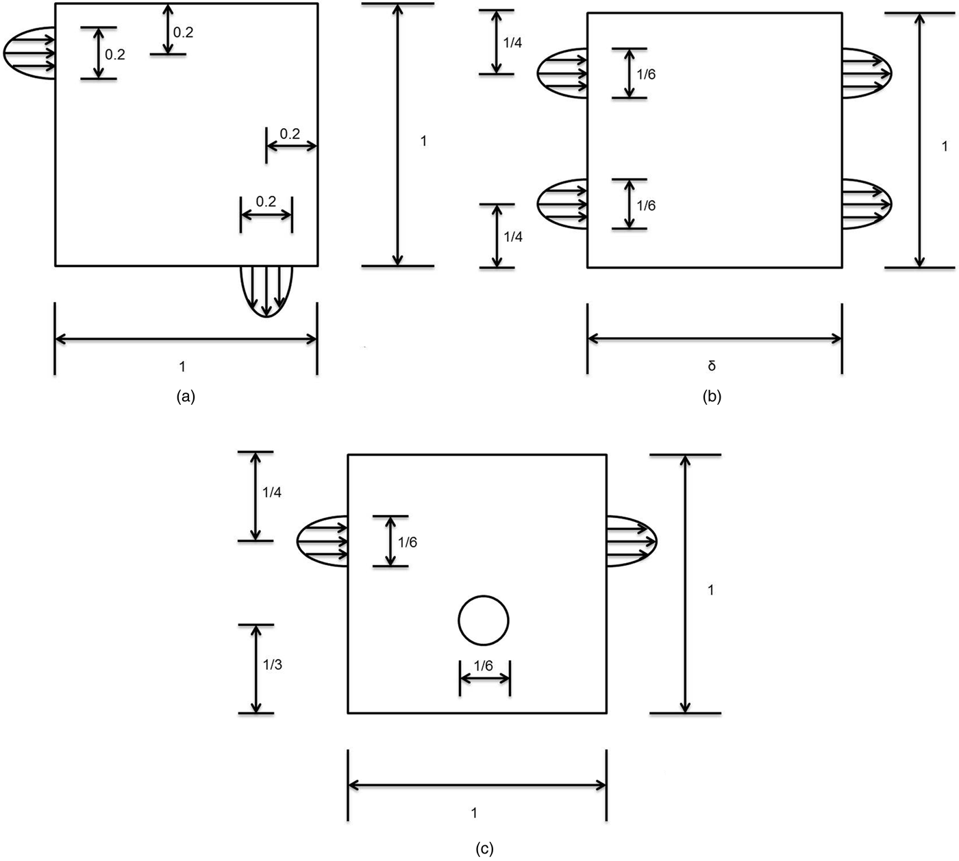
There are three typical benchmark problems in the field of topology optimization of fluid channels that have been discussed by many scientists. Borrvall and Petersson (Reference Borrvall and Petersson2003), the pioneer in using topology optimization methods for channel layout design in 2003, defined these problems. Guest and Prévost (Reference Guest and Prévost2006b), Challis and Guest (Reference Challis and Guest2009), and Jang et al. (Reference Jang, Panganiban and Chung2010) are other scientists who resolved all or some of these benchmark examples. Figure 14 represents these three test problems (Borrvall & Petersson, Reference Borrvall and Petersson2003).
The (a) design domain for the pipe bend example, (b) design domain for the double pipe example, and (c) design domain with a force term (Borrvall & Petersson, Reference Borrvall and Petersson2003).
In Figure 14b the length of the design domain is variable. The design objective of these problems is to minimize the dissipated power in the fluid, subject to a fluid volume constraint (Borrvall & Petersson, Reference Borrvall and Petersson2003). Minimizing this objective reduces drag or pressure drop, which is vital in applications that require minimum head loss, such as biofluid mechanics, microfluidics, and many other industrial processes. Time is an important secondary objective for these benchmark examples. Challis and Guest (Reference Challis and Guest2009) give the precise time required for solving the examples with different approaches, such as material distribution and the level set method.
Achieved results of Borrvall and Petersson (Reference Borrvall and Petersson2003; Figs. 7, 11, and 13 of the study) have been approved by other scientists (Guest & Prévost, Reference Guest and Prévost2006a; Challis & Guest, Reference Challis and Guest2009; Jang et al., Reference Jang, Panganiban and Chung2010), however, with slightly different optimal objective values but significant changes in the required computational power and time. The registered time by Challis and Guest (Reference Challis and Guest2009), who have used a level set topology optimization method, is considered for comparison with results achieved with the developed method in this study. With a single core of a 2.0 GHz dual core AMD Opteron processor, 0.08 h is required for a two-dimensional pipe bend problem on a 100 × 100 element mesh and 0.73 h for a 200 × 200 element mesh (Challis & Guest, Reference Challis and Guest2009). The results of the double pipe example for δ = 1 on a 144 × 144 element mesh and for δ = 1.5 on a 216 × 144 element mesh are 0.23 and 0.48 h, respectively (Challis & Guest, Reference Challis and Guest2009). These values increase dramatically when facing 3-D problems. Figure 10 of Challis and Guest (Reference Challis and Guest2009) shows the optimized 3-D pipe bend on a mesh with 50 × 50 × 20 elements, which requires 3.35 h. This shows that for real industrial problems, which are mainly in 3-D, the time is an important issue.
Due to significant differences between the developed approach in this study and the aforementioned topology optimization methods, the results must not be compared merely based on objective function values. Furthermore, the benchmark examples are two-dimensional, whereas the approach in this study is developed for 3-D problems. Therefore, the main comparison is between the concepts of a single representation method with a multiple representations approach. Figure 15 shows all three representations of the developed approach for the first example: graph representation, 3-D shape, and simulation model. In Figure 15 for better visualization of graphs, the minimum size of graph elements (arcs) is increased, and this causes some not smooth corners in the channel shape, which can be avoided through increasing number of arcs (decreasing minimum arc size). In the following, the reasons behind all three representations are discussed.
Three representations of a problem.
The first representation is devoted to create, edit, display, and manipulate the shape and topology of channels. The layout might have any size or complexity; the same rules can be used. In this level of information (representation), no trace of simulation model parameters, such as fluid equation, Reynolds number, compressibility, or noncompressibility, can be found. Therefore, the designer can use the same type of rules for different types of fluids as well. Furthermore, changing the topology and shape of the channels can be accomplished in a fraction of a second.
Figure 16 shows the graph representation of the benchmark examples. These solutions have the same topology as those represented in Borrvall and Petersson (Reference Borrvall and Petersson2003), Guest and Prévost (Reference Guest and Prévost2006a), Challis and Guest (Reference Challis and Guest2009), and Jang et al. (Reference Jang, Panganiban and Chung2010). For the double pipe example, a few other topologies are suggested with the approach; the candidates with inferior performances are filtered out after Optimizations I and II.
Topological representation of benchmark examples.
The second representation (a 3-D shape representation of graphs) has two functionalities. It is as an intermediary stage between the first and the third levels of information. It contains more information than a graph, but still not enough for the evaluation. Its second important task is to be used in other downstream applications without any postprocessing, which is normally required for grid-based or level set topology optimization methods. Manufacturability is another important issue of other methods, which is solved with this representation.
The third representation includes information about the fluid model, boundary conditions, loads, and the mesh. This information is used to evaluate the quality of generated topologies and guide the shape optimization process. The approach reduces complex topology optimization challenges into straightforward shape optimization problems. This is true especially for simple to medium-size problems, with a moderate number of topological variants such as the benchmark examples. A closer study of the benchmark examples reveals that they have no or very little topological complexity. For instance, in the case of first and third examples, there is only one topological variant, so the generation is done in very little time and the evaluation is also very fast (<30 s). In the case of the double pipe, there are fewer than 10 different valid topologies possible. The first stage of the design (shape and topology generation) requires less than a second to create the candidates. The transformation takes about 3 s, and the evaluation phase requires about 60 s (with a single core of a processor) for meshing and evaluating each candidate. Again the most time-consuming part of the design is the evaluation. This shows that for small and middle-size layout problems with a moderate number of candidates (fewer than 1000), the topology optimization task is reduced to a shape optimization problem with a very limited number of control parameters.
A single core of a virtual machine, installed on a machine with an Intel(R) Xeon(R) 3.7 GHz processor, is assigned to solve the benchmark examples. Because the only 3-D solution of the benchmark examples in Figure 14 (with detailed information about the benchmark results such as time) is for the pipe bend problem, it has been chosen for the comparison. However, second and third examples follow the same line as the first example. The creation of the topology in Figure 15 and its conversion to a 3-D shape needs less than 0.2 s (0.19 s), because this layout problem has only one solution and required no optimization. The evaluation was more time consuming; it required about 30 s for one candidate (with a single core of the processor) to generate a Tetrahedron mesh with 27,726 elements and evaluate it in OpenFOAM solver. Altogether, 30.2 s was required to reach the solution in Figure 15. It is not fair to compare this time with 3.35 h for a 3-D pipe bend in Figure 10 of Challis and Guest (Reference Challis and Guest2009), because the control parameters of the third parameter set are obtained through trial and error. Furthermore, in more complicated problems, the number of design solutions and candidates, which are passed to the CFD evaluation phase, increases, which subsequently increases the overall required time to solve the problem. If one wants to optimize the shape of the channel layout (three parameters of parameter set 3), because only 30 s for each evaluation is required, the optimum shape can be obtained very quickly. It is important to emphasize that time is not the sole comparison basis between approaches. The developed approach is able to handle problems that are very difficult if at all possible for other methods, such as very large-scale 3-D problems with arbitrary flow directions, high Reynolds number, and different fluid types in the same layout design.
4.2. Layout design of a flow distributor
Figure 17 shows the seed graph of a simple flow distributor with one inlet and five outlets. Distributors are used when uniform distribution of fuel to fuel cells in a stack is required (Liu & Li, Reference Liu and Li2013). In this study, the aim is to have a total minimum head loss; therefore, the flow might be slightly different at different outlets.
Seed graph of a channel problem with one inlet and five outlets.
As illustrated in Figure 1, the first step of the design synthesis is to search the design space to find all valid candidates and store them in a sorted list. The search algorithm required just 102 s to search the entire design space and create 1223 valid solutions. Figure 18 shows six different candidates that has been chosen between the top 4% of all candidates based on initial evaluation. Although the shapes of all these candidates are different, many of them have the same topology. For instance, candidates (a), (c), and (f) of Figure 18 have exactly the same topology, however, with different shapes. The only way to find the similar topologies is after Optimization II. This optimization changes the shape of the candidates and moves the position of the intermediate nodes to reach minimum head loss. At this stage, the duplicates can be removed from the list of candidates.
Six random candidates between the best 4% of all 1223 candidates.
After storing all valid candidates in a sorted list, they must be optimized to find candidates with best performance (here minimum head loss). The required time for both optimizations depends upon number of arcs and intermediate nodes in the graph; it varies from a fraction of a second in most cases to maximum a few seconds. However, it is not necessary to evaluate all candidates; often the best candidate is between the top 10% of all candidates that have been initially evaluated. In Figure 19a, the best candidate with the best objective function values is depicted. It is the optimized result of (a), (c), and (f) in Figure 18. The objective function values for the first optimization of all six designs are equal to zero. This is because the sum total of all cross section areas of the outlets is equal to the inlet, because no compression (in compressible fluids) is desired. In the second step, all designs are very straightforward for the optimization to be solved. In cases in which both number of inlets and outlets is more than one, the optimization is harder to be solved. The second objective function value equals the length of all arcs plus changes in the direction of flow from inlet to each outlet. Candidate (a) in Figure 18 shows the best value; and candidate (f) has the second lowest value. The objective functions of all candidates in the Figure 18 are as following: (a) 3027.33, (b) 3594.97, (c) 3851.21, (d) 4011.61, (e) 4157.42, and (f) 3503.47.
The best candidate after Optimization II (a), and detailed shape design (b).
Up to this stage, the topology of the candidates is fixed and the shape is also roughly fixed. In the third stage of the shape and topology generation phase, the detailed shape design of candidates is accomplished. This stage is to further smooth the flow passage at joints in order to reduce the head loss due to sharp angle changes in the flow. This stage is not necessary for all applications because it creates very curvy design shapes. Although these shapes have less head loss, their production might be very tedious, especially in large-scale problems. For instance, the fuel cell distributors might not require the detailed shape design, but for the microfluidic structures it might be very urgent. Figure 19b shows the detailed design of the best candidate.
Although the graphs are represented in two dimensions (x, y), they have three dimensions, and all graph transformations are applied upon three dimensions. The third dimension cannot be visualized in the GraphSynth environment; for 3-D visualization, they must be transformed into shapes via Parasolid Kernel. Figure 20 shows a flow distributor with outlets at different z positions. The graph of Figure 20 is different from that of Figure 20b because of considering z position for nodes. The transformation of the graph in Figure 20 to the 3-D STL shape requires only 3 s.
A three-dimensional flow distributor.
Generally, the best design candidate is found during the first two steps of the shape and topology generation phase. During these steps, no CFD evaluation is performed to find the head loss of the channel designs, but three simple facts that cause the head loss in channels are considered: length of channels, changes in the direction of flow, and finally changes in the radius of channels. Considering these criteria, the best candidate is a candidate that in the shortest possible way, with minimum changes in the direction of flow and minimum changes of the channel radiuses, transports a fluid from one or many sources to one or many destinations. After transforming the best or few best designs into 3-D shapes, they can be directly used without even CFD evaluation, if the control parameters (set 3) and weighting factors of objective functions are adequately assigned.
Figure 21 shows the pressure profile of the best candidate, which has been calculated in the CFD solver and visualized in Salome postprocessor (Open CASCADE, 2013). For the simulation, the flow is considered as a single-phase steady-state flow without turbulence. Density of the flow is the same as water (1000 kg/m3) but with a very high viscosity (1 Pa s). The gravity is not considered, and the initial velocity at the inlet is 1 m/s. As can be seen in Figure 21, the critical point of the design is at the base of the fork and the pressure at the middle outlet is higher than all others, which was predictable. The pressure for all other outlets is pretty similar, but not the same, because in the objective functions minimizing the overall head loss was the goal.
The computational fluid dynamics (CFD) evaluation results of the best candidate in Figure 20.
As discussed earlier, the simulation model is disjoint from the synthesis model and only in the last phase of the design the CFD evaluation is it considered; therefore, the above-mentioned specifications of the flow can be altered. However, by changing boundary conditions, such as speed, the control parameters and objective function weighting factors must be updated too.
5. CONCLUSIONS
A new approach for shape and topology optimization of fluid channels using generative design methods is proposed. This multiple representation approach uses graphs to represent the topology and shape of channel layouts. This allows a very fast generation of topological solutions for a design problem. Based on results of two optimization functions, the best solutions are stored in a data base for further detailed shape design. To evaluate solutions with a CFD solver, the graphs are converted to 3-D shapes via a Parasolid kernel. These shapes can be used directly in downstream applications and need no extra postprocessing. The simulation model is fully separated; therefore, it is possible to solve full Navier–Stokes systems or problems that have compressible fluids with high Reynolds number and arbitrary flow directions at inlets and outlets. Large-scale problems, problems with more than one fluid type, for which the mixing must be avoided, are also solvable. The deficiency of other methods in solving these types of problems comes from the fact that they use the same representation for evaluation and generation. The dual objective function allows designers to reach desired compression, decompression, and velocity of flow at each outlet while simultaneously minimizing the head loss. The rules are so flexible and separate from simulation models that might be used to create channels for other domains such as heat transfer to transfer maximum heat from sources to coolers. The current state of the approach is not designed to be used in optimizing reverse flows and mixtures.
The ongoing research of this study is on automating the last phase of the design synthesis approach: CFD evaluation. Implementation of this step is necessary to have a fast tuning of the control parameters of the parameter set 3. For tuning each parameter a few CFD evaluations are required. Using B-Splines and loft function instead of CSG primitives to convert graphs into 3-D shapes is another possible research area, which would yield smoother channels. Another important field of research that can increase the performance of the approach is inserting obstacles in the seed graph. The reason for this investigation is that obstacles are an undeniable part of the real-world design problems. An interesting field of research might be using the output results of the approach as input for conventional topology optimization methods. This combination would allow the channel radii to be fine-tuned. It would guarantee a very fast convergence to the optimum solution owing to a very exact initial design, and many problems could be solved that are hitherto not solvable, such as multiple fluids.
ACKNOWLEDGMENTS
We are grateful for the support of the Technische Universität München, Institute for Advanced Study, funded by the German Excellence Initiative.
Amir Hooshmand is a Graduate Researcher at the Technische Universität München, Germany. His PhD research focuses on capturing and using design information and knowledge in the synthesis processes using generative graph grammars. He has a master of science degree in mechanical and process engineering from Technische Universität Darmstadt.
Matthew I. Campbell is a Professor of mechanical engineering at Oregon State University. He received his PhD from Carnegie Mellon University in 2000 with honors and was a member of Phi Kappa Phi and Pi Tau Sigma. For more than 15 years, he has focused on methods that independently create solutions for typical mechanical engineering design problems like gear trains, sheet metal, planar mechanisms, and planning for manufacturing, assembly, and disassembly. As such, he has become a world-class expert in a variety of fields such as machine design, design theory, artificial intelligence, graph theory, and numerical optimization. Dr. Campbell has over 100 published articles and has been acknowledged with best paper awards at ASME, ASEE, and the Design Society conferences. His research focuses on automating difficult or tedious engineering design tasks.