


Introduction
Storglaciären (Fig. 1) is a sub-polar glacier in the Kebnekaise region of northern Sweden. Glaciological and hydrological studies indicate the importance of the water regime in affecting the dynamical behaviour of this glacier (Reference Hooke, Brzozowski and BrongeHooke and others, 1983). To understand this role is difficult because little is known about the distribution of water within and at the bed of the glacier. In the present paper we report a polarization-sensitive radio-echo experiment designed to search for and examine radio echoes from major individual englacial targets; this it was hoped would provide insight into the nature of the targets and hence perhaps of the englacial water system.
Map of Storglaciären reproduced with permission from Reference BjörnssonBjörnsson (1981).

Echo sounding of glaciers containing temperate ice is usually carried out with a monocycle radio echo-sounder having a centre frequency of a few MHz. Reference BjörnssonBjörnsson (1981) used such an instrument to map the topography of the bed of Storglaciären. A radio-echo traverse across the glacier typically reveals not only the bed echo but also echoes from englacial targets. The latter usually exhibit strong spatial fading. The fading rate tells us little more than that there are many targets present in the ice but statistical studies of the power returned as a function of range do provide useful information about englacial targets. Reference Walford, Kennett and HolmlundWalford and others (1986) found that, in the temperate ice which occurs generally below 30–40 m depth at Storglaciären, the total scattering cross-sectional area per unit volume was frequency-dependent. It increased by between one and two orders of magnitude when the frequency was changed from 6 to 65 MHz. Rayleigh scattering, which occurs with targets much smaller than the radio wavelength in water, is characterized by a scattering cross-section proportional to the fourth power of frequency. They also found from a study of echo polarization that there is a statistically significant preferred target orientation, possibly related to crevassing in the accumulation area. Finally, they found evidence of resonant scattering. This can occur when a large englacial water body is excited by the transmitted wave and subsequently decays, emitting a wave train the duration of which is determined by the selectivity of the excited modes. At 6 MHz, the radio wavelength in water is 5 m and so a water body of metric dimensions could exhibit resonant scattering. Glacier water is very pure and so there is no difficulty in accounting for the necessary selectivity.
Aperture Synthesis
The synthetic technique employed is similar in principle to the “radio-echo microscope” technique which has been used for mapping the bed of a polar glacier (Reference Walford and HarperWalford and Harper, 1981). The present experiment differs, however, in three respects. First, we are now investigating a three-dimensional target distribution rather than the continuous surface of a glacier bed. Secondly, we are using a monocycle radio echo-sounder rather than a quasi-monochromatic pulsed echo-sounder. Finally, we are measuring the full polarization characteristics of the echoes rather than just one component.
The principle of the method is that echoes are recorded over an array of sites on the glacier surface. They are transferred to a computer, where they are combined additively with suitable time-shifts in such a way that returns from a selected cell within the glacier add coherently. Echoes from targets outside the chosen cell add incoherently. By this means, we can “focus” on one particular selected region within the glacier at a time. By altering the time-shifts, we can adjust the point of focus and explore the target distribution within a volume of ice beneath the aperture.
Polarization
In this section we consider how polarized transient echoes from englacial targets may be represented.
The vector theory of the scattering of harmonic, electromagnetic waves is well-developed (Reference Beek and Birksvan Beek, 1967; Reference BoernerBoerner, 1980). The polarization states of the incident and scattered waves are usually represented by complex vectors, h I and h S, and the scattering characteristics of the target by a symmetric 2×2 matrix, [S], with complex coefficients. Then

Fourier methods could be used in order to apply this harmonic theory to monocycle signals, remembering that [S] in general depends on frequency. However, it is simpler, both analytically and conceptually, to discuss the scattering by time-domain analysis. To do this, we represent the target by a real, symmetrical, matrix [S(r)], the elements of which are functions of range. It is sometimes convenient to use a time-domain version, [St(t)]= [S(1/2vt)] where ν is the wave velocity of radio signals in ice. The definition of [St(t)] follows shortly.
For a given orientation of the transmitting antenna, the electric field incident on the target can be written:
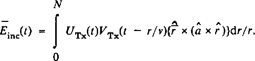
In equation (2)
VTx(t) is the excitation voltage signal applied to the transmitting antenna terminals and UTx(t) represents the impulse response of the antenna in transmission (Reference KandaKanda, 1980). â is a unit vector defining the antenna orientation, r is the magnitude of the vector
r
and  is the unit vector in the direction of
r
…. r ≫λice. The vector product gives the direction of the linearly polarized electric field produced at
r
by the antenna. equation (2) applies for an antenna with a sinusoidal radiation polar diagram. A resistively loaded dipole approximates to such an antenna. The return from a target at r can be written:

ν is the wave velocity in ice. The asterisk denotes convolution. We have supposed for simplicity that the two antennae are at the same point on the glacier surface. equation (3) may be regarded as defining the target-scattering matrix function, [St(t)]- The voltage signal at the terminals of the receiving antenna is given by the convolution:

where UREC(t) is the impulse response of the receiving antenna (Reference KandaKanda, 1980) and  is a unit vector defining the receiving antenna direction. The scalar product approximately represents the effect of the polar diagram of the receiving antenna. We now define:

and

Combining Equations (2), (3), (4), (5), and (6), and rearranging, we obtain for a given antennae configuration:

A(r) is an effective scattering function which takes account of the orientation of the transmitting and receiving antennae, the target-scattering matrix, its range, and the direction in which it lies. It is equivalent to the function g(r) which Reference BerryBerry (1972, Reference Berry1973) introduced in his scalar theory of the scattering of pulsed waves from rough surfaces. F(t) is an effective transmitted pulse which incorporates the impulse responses of the antennae. It is essentially the same as the function F(t) defined by Berry and in principle could be observed as the echo from a smooth, plane reflector.
Echoes from an array of sites in the glacier surface are time-shifted and added together to give synthetic echoes, which we denote ΣVi(t), i = Ν, Ε, X, respectively. Suitable time shifts are calculated so that signals from a target present at a chosen position,
r
, add constructively. With the radar antennae at
R
, the time shift is  A condition for constructive addition to occur is that the target-scattering matrix, [S(r)], should not vary rapidly with
R
; that is to say with the direction of view as we move the antennae about within the aperture. This condition constitutes a quite severe limitation: it excludes, for example, irregular water-filled cavities with dimensions of more than approximately a few metres, because the wavelength of the radio waves in water is only approximately 5 m.
The Radio Echo-sounder
The radio echo-sounder used for the present experiment was a bistatic, monocycle instrument which transmits a pulse of centre frequency 6 MHz. The two antennae were centre-fed, resistively loaded dipoles each 2 × 6.4 m long, supported with lightweight, insulating, “roach poles”. During the experiment we required well-defined, constant synchronization between transmitter and display, independent of the relative orientation of the antennae. The pulsed transmitter was therefore synchronized with the display by means of an optical fibre link. Echoes were recorded photographically, to be digitized later using a micro-densitometer. This method of digitizing is tedious but it provided very good quality data, with an excellent signal-to-noise ratio. It was employed because an electronic data-acquisition system proved inadequate in the field.
Figure 1 shows the position of the experimental site, near the centre line and approximately 0.5 km down-glacier of the equilibrium line. The aperture was a square array of 10 × 10 stations, 5 m apart. This spacing was decided upon in the field after observing the spatial fading rate. The dimensions of the aperture were thus a few half-wavelengths in ice.
The radio echo-sounder can resolve two targets differing in range by approximately 15 m, one-half the length of the transmitter pulse in ice. When used as a radio-echo microscope, the resolution normal to the range vector depends upon diffraction and is determined by the effective projected dimensions of the aperture, as seen from the target.
Treatment of Results
Three independent aperture-synthesis computations have been carried out, using the three independent sets of echoes Vi(t), i = Ν, Ε, X. Figure 2 shows the site geometry and the coordinate system. We define an energy wi(r,θ,Φ), for each polarization channel, thus:

In Figure 3 are plotted stereographic maps of the energy wi(r,θ,Φ),for r = 100 m. Each image in Figure 3 shows a few bright spots and in some directions there is a spot on more than one image. A statistical test using jumbled echoes shows that such a distribution of w(r,θ,Φ), is unlikely to arise at random. Therefore, the aperture-synthesis computation has succeeded in identifying directions along which strong localized targets occur.
Geometry and coordinate systems used in discussing the aperture-synthesis experiment.

Stereographic projections showing, for r = 100 m, the distributions of echo energy W¡(r,θ,Φ>) with i =Ν, Ε, and X, respectively. The white cross marks the vertically downward direction. West is approximately the up-glacier direction.
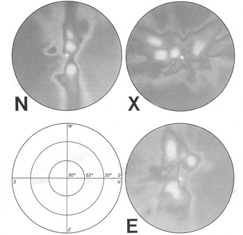
In Figure 4 we plot the synthetic radio echoes ΣV¡(t), for i = Ν, Ε, X, found when we “focus” on a chosen bright spot. This is done for six prominent individual targets, labelled T1-T6 in Figure 5. In all six cases, a clear relationship between pronounced transients is found in at least two of the polarization channels, at approximately the same time. The range of each previously identified target is indicated by the time delay of the transient echoes. All targets are found to lie between 50 and 80 m deep. We conclude that the method of aperture synthesis successfully isolates targets in a temperate glacier which could not otherwise be individually observed. Each target is individually characterized by the corresponding synthetic echo, Σv¡(t), = Ν, Ε, Χ.
Synthetic echo wave forms Σv¡(t) for i = Ν, Ε, X, for targets T1-T6.

Stereographic map showing the positions of the six prominent targets revealed by aperture synthesis. The orientation and scale are the same as in Figure 3.

It would be desirable next to solve the radio-echo inverse problem, finding [S(r)] for each individual target from its synthetic echoes, knowing the form of the transmitted wave. One could then consider quite separately the glaciological question of what plausible physical targets might account for [S(r)]. We have attempted to calculate [S(r)] by deconvolution both in the frequency domain and in the time domain, but the results were very unsatisfactory. This is partly because the transmitted wave form is not well known and it does not approximate well to an impulse function of time, which is the ideal wave form for the purpose. Thirdly, too much noise is produced by the out-of-focus targets. In these circumstances, a Monte Carlo approach might be successful but we have not considered it worthwhile to pursue this option. Reference KennettKennett (unpublished) offered an approximate qualitative analysis. He measured the peak amplitudes of Σv¡(t), = Ν, Ε, Χ. for each target and used them to calculate a point target-scattering matrix, [S(r)], with real coefficients. He modelled the targets as water-filled or air-filled spheroids and found that, except for T6, the eigenvalue ratios of [S(r)] were too great to be accounted for by air-filled cavities. Such an analysis is based upon the assumption that the three synthetic echoes, Σv¡(t),, have approximately the same wave form, differing in other words only by a scalar factor (Fig. 4).
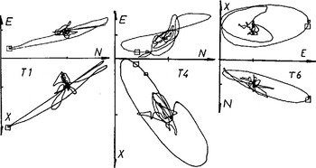
Although we have not solved the inverse problem satisfactorily, the following discussion gives some insight into the symmetry of the target responsible for a given echo. The synthetic echo wave forms, Σv¡(t), characterize each target as observed in the experiment. Imagine a three-dimensional graph, with Cartesian axes (n, e, x) along which we plot Σv¡(t), with i = Ν, Ε, and X, respectively. The result would be a smooth, continuous curve with delay time as a parameter. We refer to the curve as an echo-polarization signature. We have constructed wire models of the signatures for each of the six targets: these cannot, of course, be reproduced in a journal but in Figure 6 we plot a suitable projection for three of them. In each case the large loop is the echo signature, clearly distinguished from the background. The signature of target T1 is an approximately one-dimensional loop, the signature of targets T4 and T6 are approximately planar.
Projections of the echo-polarization signatures for targets T1, T4, and T6.
It is not difficult to calculate, using equation (7), the signature to be expected for a target with a given scattering matrix [S(r)]. A simple example is provided by considering a target at a point vertically below the centre of the aperture, with a target-scattering matrix:
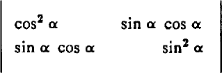
We call this a line matrix: it produces a linear polarization signature, executed as F(t), lying in the line (cos2 α, sin2α, cos α sin α). The target corresponding to the line matrix might have the form of a long, thin needle lying in the horizontal plane, with bearing α. As the needle is rotated about the line of sight, the linear signature moves on the surface of the outer cone shown in Figure 7.
Sketch of the three-dimensional Cartesian space [n, e, x] used in discussing echo-polarization signatures.

If we add two line matrices at the same range but with different amplitudes and angles α, the echo signature is still linear in shape but lies on the surface of the smaller cone in Figure 7. A target with elliptical symmetry would produce a linear signature like this. To a good approximation, the signature of T1 is just such a signature.
If we add two line matrices which differ in range by a fraction of a wavelength and have different amplitudes and orientations, we find that the polarized echo signature is a closed smooth curve lying in the plane defined by the signatures of the individual needles. The shape of the curve is sensitive to the difference in the ranges and to their relative orientations. The signatures of T4 and T6 are approximately of this type. If we add more than two different line matrices, the signature is a curve not in general confined to a plane.
The signatures of the observed targets are in most cases approximately linear or planar and not more complicated. There are two reasons for this. First, as we have pointed out, aperture synthesis is not expected to reveal large targets of complicated geometry for which the target-scattering matrix would vary over the aperture. Secondly, the limited band width of the radio echo-sounder means that the observed signatures can only be rather smooth curves; they cannot execute complicated three-dimensional manoeuvres during the limited duration of the synthesized echo.
Conclusions
Radio echoes from localized englacial structures have been isolated in an aperture-synthesis experiment using a monocycle radio echo-sounder. Analysis of the echoes by formal deconvolution procedures fails for several reasons. However, the echo-polarization signatures of the individual targets are quite simple and can be interpreted in terms of target models of simple symmetry. This puts some limitations on possible physical target models. The simplicity arises because the aperture synthesis is not expected to isolate large targets of complex shape. Because of the high echo strength, the targets revealed at Storglaciären, with possibly one exception, were almost certainly water bodies, but we cannot say whether they were part of a connected system of englacial channels or not. This could perhaps be established by tracer experiments using radio-transmitting probes (Reference WalfordWalford, 1987).
The technique of radio-echo aperture-synthesis is not difficult, although it is somewhat laborious in the field and the data require careful analysis on a large computer. A full polarization study greatly aids both in identifying and characterizing significant targets. For such a study, an optic fibre provides reliable synchronization of the transmitter and receiver, without affecting the radio signals.
Acknowledgements
The authors would like to thank Professor J.F. Nye, University of Bristol, for many useful discussions and Dr R. LeB. Hooke, P. Holmlund, and others at Tarfala field station, Sweden, for their help. The work was supported by the U.K. Natural Environmental Research Council.



