1 Introduction
Taylor–Couette (TC) flow (Grossmann, Lohse & Sun Reference Grossmann, Lohse and Sun2016), in which a fluid is confined between two rotating cylinders, and Rayleigh–Bénard (RB) flow (Ahlers, Grossmann & Lohse Reference Ahlers, Grossmann and Lohse2009), in which a fluid is heated from below and cooled from above, are the two most famous examples for turbulent flows in closed system, in which exact energy balances hold and global transport properties can be connected to the energy dissipation rates. Due to the close analogy (Eckhardt, Grossmann & Lohse Reference Eckhardt, Grossmann and Lohse2007a
,Reference Eckhardt, Grossmann and Lohse
b
), they have been called the twins of turbulence research (Busse Reference Busse2012). In the TC system, the global transport property is often expressed as torque
 $\unicode[STIX]{x1D70F}$
, which drives the cylinder at a constant angular velocity. Following the analogy (Eckhardt et al.
Reference Eckhardt, Grossmann and Lohse2007b
) between the angular velocity flux from the inner to the outer wall in TC and heat flux from bottom to top plate in RB flow, the torque in dimensionless form can be expressed as a Nusselt number
 $Nu_{\unicode[STIX]{x1D714}}$
, which for smooth cylinders and in the ultimate turbulent regime was shown to have an effective scaling
 $Nu_{\unicode[STIX]{x1D714}}\propto Ta^{0.38}$
with the later defined Taylor number
 $Ta$
(van Gils et al.
Reference van Gils, Huisman, Bruggert, Sun and Lohse2011; Ostilla-Mónico et al.
Reference Ostilla-Mónico, van der Poel, Verzicco, Grossmann and Lohse2014a
,Reference Ostilla-Mónico, van der Poel, Verzicco, Grossmann and Lohse
b
), identical to the effective scaling
 $Nu\propto Ra^{0.38}$
found in ultimate RB turbulence in terms of Nusselt number
 $Nu$
and Rayleigh number
 $Ra$
(He et al.
Reference He, Funfschilling, Bodenschatz and Ahlers2012a
,Reference He, Funfschilling, Nobach, Bodenschatz and Ahlers
b
). This effective scaling in the ultimate regime has been explained by Grossmann & Lohse (Reference Grossmann and Lohse2011) as the pure ultimate regime scaling exponent
 $1/2$
(Kraichnan Reference Kraichnan1962) with logarithmic correction due to the interplay between bulk and turbulent boundary layer (BL).
Altering the boundary conditions by implementing rough boundaries is thought to be one way to reduce the logarithmic correction because roughness can modify the boundary layer and hence the boundary–bulk interaction. In RB convection, roughness has already been employed in many studies (Shen, Tong & Xia Reference Shen, Tong and Xia1996; Ciliberto & Laroche Reference Ciliberto and Laroche1999; Du & Tong Reference Du and Tong2000; Roche et al.
Reference Roche, Castaing, Chabaud and Hébral2001; Stringano, Pascazio & Verzicco Reference Stringano, Pascazio and Verzicco2006; Wagner & Shishkina Reference Wagner and Shishkina2014), however, the results concerning the change of the scaling exponent are still elusive (Ahlers et al.
Reference Ahlers, Grossmann and Lohse2009; Tisserand et al.
Reference Tisserand, Creyssels, Gasteuil, Pabiou, Gibert, Castaing and Chillà2011). For TC flow the studies regarding rough boundaries have attracted much less attention. The only two examples are by Cadot et al. (Reference Cadot, Couder, Daerr, Douady and Tsinober1997) and van den Berg et al. (Reference van den Berg, Doering, Lohse and Lathrop2003) and indeed for rough walls, an increase of the torque scaling exponent towards the pure ultimate scaling
 $Nu_{\unicode[STIX]{x1D714}}\propto Ta^{1/2}$
has been found. Those global measurements however did not provide information on local flow details, therefore the exact mechanism of the torque enhancement could not be elucidated. Most importantly, knowledge on how the roughness changes the flow structure and how the flow structure affects the torque scaling is still missing.
In this manuscript, direct numerical simulations (DNS) are performed to simulate Taylor–Couette flow with a rough inner wall. This configuration allows us to dissect directly smooth turbulent boundary layer, rough turbulent boundary layer and bulk interactions simultaneously. Our aim here is to demonstrate that: (i) pressure dominance of the torque at the rough wall is of prime importance in changing the flow structure; (ii) pressure induced separation causes an increase of the dissipation through the vortex-shedding towards the bulk, rather than via a large shear rate very close to the wall as in the smooth case. The consequence is an increase of the scaling exponent.
2 Numerical techniques and parameters
For the DNS a second-order finite difference code (Verzicco & Orlandi Reference Verzicco and Orlandi1996; van der Poel et al.
Reference van der Poel, Ostilla-Mónico, Donners and Verzicco2015) is employed, in combination with an immersed boundary method (Fadlun et al.
Reference Fadlun, Verzicco, Orlandi and Mohd-Yusof2000) to deal with the roughness. The radius ratio is
 $\unicode[STIX]{x1D702}=r_{i}/r_{o}=0.714$
, where
 $r_{i}$
and
 $r_{o}$
are the inner and outer radii, respectively. The aspect ratio of the computational domain is
 $\unicode[STIX]{x1D6E4}=L/d=2.094$
, where
 $L$
is the axial periodicity length and
 $d$
the gap width
 $d=r_{o}-r_{i}$
. With such
 $\unicode[STIX]{x1D6E4}$
, we can have a relatively small computational box with a pair of Taylor vortices rotating in opposite directions. The inner cylinder is roughened by attaching six vertical strips of square cross-section (edge width
 $h=0.1d$
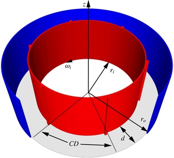
) which are equally spaced in azimuthal angle, similar to the procedure used in Cadot et al. (Reference Cadot, Couder, Daerr, Douady and Tsinober1997), van den Berg et al. (Reference van den Berg, Doering, Lohse and Lathrop2003). A schematic view of the geometry is seen in figure 1. A rotational symmetry of order six is implemented to reduce computational cost while not affecting the results (Brauckmann & Eckhardt Reference Brauckmann and Eckhardt2013; Ostilla-Mónico et al.
Reference Ostilla-Mónico, van der Poel, Verzicco, Grossmann and Lohse2014a
). As a result, in our azimuthally reduced domain, only one square rough element exists. Here we focus on the case of inner cylinder rotation with angular velocity
 $\unicode[STIX]{x1D714}_{i}$
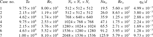
and fixed outer cylinder. The appropriate number of grid points is chosen to make sure that the torque difference between the inner and outer cylinder is less than one per cent. The parameters are shown in detail in table 1.
Schematic view of the Taylor–Couette system with roughness. The inner cylinder with radius
 $r_{i}$
is rotating with angular velocity
 $\unicode[STIX]{x1D714}_{i}$
. The outer cylinder with radius
 $r_{o}$
is at rest. The gap width is
 $d=r_{o}-r_{i}$
. The rough elements are six square vertical stripes positioned equidistantly on the inner cylinder wall. The height of the rough element is
 $0.1d$
. In our DNS, a rotational symmetry of six is used. The computational domain contains
 $1/6$
of the azimuthal width and has one rough element on the inner cylinder. CD: computation domain.

In order to show the modification of roughness to the global transport properties, from DNS, we extract
 $Nu_{\unicode[STIX]{x1D714}}$
and the wind Reynolds number
 $Re_{w}$
as a function of
 $Ta$
, which are defined as,
 $$\begin{eqnarray}\displaystyle Nu_{\unicode[STIX]{x1D714}}=\unicode[STIX]{x1D70F}/\unicode[STIX]{x1D70F}_{pa}, & & \displaystyle\end{eqnarray}$$
where
 $\unicode[STIX]{x1D70F}_{pa}$
is the torque required to drive the system in the purely azimuthal and laminar case, and
 $$\begin{eqnarray}\displaystyle Re_{w}=\unicode[STIX]{x1D70E}(u_{r})d/\unicode[STIX]{x1D708}, & & \displaystyle\end{eqnarray}$$
where
 $\unicode[STIX]{x1D70E}(u_{r})$
is the standard deviation of radial velocity and
 $\unicode[STIX]{x1D708}$
the kinematic viscosity of the fluid. The Taylor number is defined as
 $$\begin{eqnarray}\displaystyle Ta=\frac{1}{64}\frac{(1+\unicode[STIX]{x1D702})^{4}}{\unicode[STIX]{x1D702}^{2}}d^{2}(r_{i}+r_{o})^{2}\unicode[STIX]{x1D714}_{i}^{2}\unicode[STIX]{x1D708}^{-2}, & & \displaystyle\end{eqnarray}$$
where
 $\unicode[STIX]{x1D714}_{i}$
is the angular velocity of the inner cylinder. Another alternative way to characterize the system is by using the inner cylinder Reynolds number
 $Re_{i}=Ud/\unicode[STIX]{x1D708}=r_{i}\unicode[STIX]{x1D714}_{i}d/\unicode[STIX]{x1D708}$
(Lathrop, Fineberg & Swinney Reference Lathrop, Fineberg and Swinney1992; Lewis & Swinney Reference Lewis and Swinney1999). Note that these two definitions can be easily transformed between each other by the relation
 $$\begin{eqnarray}\displaystyle Ta=\frac{(1+\unicode[STIX]{x1D702})^{6}}{64\unicode[STIX]{x1D702}^{4}}Re_{i}^{2}. & & \displaystyle\end{eqnarray}$$
The torque
 $\unicode[STIX]{x1D70F}$
can be further related to the friction velocity
 $u_{\unicode[STIX]{x1D70F}}$
and the viscous length scale
 $\unicode[STIX]{x1D6FF}_{\unicode[STIX]{x1D708}}$
:
 $$\begin{eqnarray}\displaystyle & \displaystyle u_{\unicode[STIX]{x1D70F}}=\sqrt{\unicode[STIX]{x1D70F}/2\unicode[STIX]{x1D70C}\unicode[STIX]{x03C0}r^{2}L}, & \displaystyle\end{eqnarray}$$
 $$\begin{eqnarray}\displaystyle & \displaystyle \unicode[STIX]{x1D6FF}_{\unicode[STIX]{x1D708}}=\unicode[STIX]{x1D708}/u_{\unicode[STIX]{x1D70F}}, & \displaystyle\end{eqnarray}$$
where
 $\unicode[STIX]{x1D70C}$
is the density of fluid and
 $r$
can be either the inner cylinder radius
 $r_{i}$
or the outer one
 $r_{o}$
.
The torque can also be expressed in the form of a friction factor
 $C_{f}$
, which is widely used for wall bounded turbulence. The relation between
 $C_{f}$
and
 $Nu_{\unicode[STIX]{x1D714}}$
is
 $$\begin{eqnarray}\displaystyle C_{f}=2\unicode[STIX]{x03C0}Nu_{\unicode[STIX]{x1D714}}J_{0}^{\unicode[STIX]{x1D714}}\unicode[STIX]{x1D708}^{-2}/Re_{i}^{2}, & & \displaystyle\end{eqnarray}$$
where
 $J_{0}^{\unicode[STIX]{x1D714}}=2\unicode[STIX]{x1D708}r_{o}^{2}r_{i}^{2}\unicode[STIX]{x1D714}_{i}/(r_{o}^{2}-r_{i}^{2})$
is the angular velocity current at the purely azimuthal laminar state.
Values of the control parameters and the numerical results of the simulations. We keep the radius ratio at
 $\unicode[STIX]{x1D702}=0.714$
and the square rough element height
 $h=0.1d$
, but we vary the
 $Ta$
and thus the
 $Re_{i}$
. The fourth column shows the number of grid points used in the azimuthal (
 $N_{\unicode[STIX]{x1D703}}$
), radial (
 $N_{r}$
) and axial direction (
 $N_{z}$
). The fifth column shows the dimensionless torque,
 $Nu_{\unicode[STIX]{x1D714}}$
. The sixth column shows the wind Reynolds number
 $Re_{w}$
. The last column details the mean Kolmogorov scale
 $\unicode[STIX]{x1D702}_{K}$
. It is obtained from the relation
 $\unicode[STIX]{x1D702}_{K}=(\unicode[STIX]{x1D708}^{3}/\unicode[STIX]{x1D716}_{u,m})^{1/4}$
, where
 $\unicode[STIX]{x1D716}_{u,m}$
is the mean kinetic dissipation rate (3.13). All of the simulations were run in reduced geometry with
 $L=2\unicode[STIX]{x03C0}/3$
and a rotation symmetry of the order 6. The corresponding cases at the same
 $Ta$
without roughness (with smooth cylinders) can be found in Ostilla et al. (Reference Ostilla, Stevens, Grossmann, Verzicco and Lohse2013), Ostilla-Mónico et al. (Reference Ostilla-Mónico, van der Poel, Verzicco, Grossmann and Lohse2014a
).

3 Results
3.1 Global scaling laws
The effective scaling relations of
 $Re_{w}$
and
 $Nu_{\unicode[STIX]{x1D714}}$
versus
 $Ta$
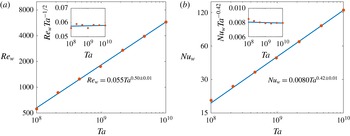
are shown in figure 2. We find
 $Re_{w}\propto Ta^{0.50\pm 0.01}$
, in accordance with the theory
 $Re_{w}\propto Ta^{1/2}$
(Grossmann & Lohse Reference Grossmann and Lohse2011) predicted for the ultimate regime with a smooth boundary. This effective scaling was also found for ultimate RB (He et al.
Reference He, Funfschilling, Nobach, Bodenschatz and Ahlers2012b
) and ultimate TC (van Gils et al.
Reference van Gils, Huisman, Bruggert, Sun and Lohse2011; Huisman et al.
Reference Huisman, van Gils, Grossmann, Sun and Lohse2012) turbulence. Indeed, the prediction for
 $Re_{w}(Ta)$
of Grossmann & Lohse (Reference Grossmann and Lohse2011) should also work for rough boundaries in the ultimate regime. It originates from the dominance of the turbulent bulk contribution to the energy dissipation rate. Once the BLs become even more turbulent through the roughness, the system will become more bulk-like and the scaling therefore should not change. The prefactor 0.055 in the effective scaling relation is larger than its counterpart for the smooth TC case where it is only 0.0424 (Huisman et al.
Reference Huisman, van Gils, Grossmann, Sun and Lohse2012) which shows that roughness facilitates the fluctuations of the wind flow rather than hindering it.
We now come to the scaling of the torque. Here, the effective scaling relation
 $Nu_{\unicode[STIX]{x1D714}}\propto Ta^{0.42\pm 0.01}$
is found. The scaling exponent is notably larger than the effective ultimate scaling exponent 0.38 seen for both smooth RB (He et al.
Reference He, Funfschilling, Nobach, Bodenschatz and Ahlers2012b
) and TC (Huisman et al.
Reference Huisman, van Gils, Grossmann, Sun and Lohse2012) flows, respectively, in the appropriate
 $Ra$
and
 $Ta$
regimes. This effective scaling exponent originates from the pure ultimate scaling
 $Nu_{\unicode[STIX]{x1D714}}\propto Ta^{1/2}$
(Kraichnan Reference Kraichnan1962), but with logarithmic corrections (Grossmann & Lohse Reference Grossmann and Lohse2011). Our finding of an increased effective scaling exponent as compared to that in the smooth case implies that roughness can reduce the logarithmic correction. This becomes possible through redistribution of the energy dissipation in radial direction. We will explain the physics behind this statement in the following paragraphs.
(a) Wind Reynolds number
 $Re_{w}$
versus Taylor number
 $Ta$
. (b) Nusselt number
 $Nu_{\unicode[STIX]{x1D714}}$
versus
 $Ta$
. The bullets are the data from simulations while the straight lines are the best fits
 $Re_{w}=0.055Ta^{0.50\pm 0.01}$
and
 $Nu_{\unicode[STIX]{x1D714}}=0.0080Ta^{0.42\pm 0.01}$
. The insets show the compensated plots
 $Re_{w}/Ta^{1/2}$
versus
 $Ta$
and
 $Nu_{\unicode[STIX]{x1D714}}/Ta^{0.42}$
versus
 $Ta$
.

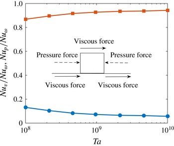
Contributions to the total torque originating from pressure
 $Nu_{p}$
(upper curve, squares) and viscous stresses
 $Nu_{v}$
(lower curve, dots) for rough boundaries. As seen, the torque mainly originates from pressure forces whereas viscous stresses contribute only for a small faction. The schematics inside the figure show how viscous forces and pressure contribute separately to the total torque.

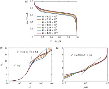
(a) Averaged azimuthal velocity profiles for varying
 $Ta$
. The shear rate is much smaller at the rough wall compared to the smooth one. The velocity in the middle of the gap is biased towards the rough wall velocity. The larger
 $Ta$
, the more the velocity profile is biased in the bulk towards the inner cylinder velocity. (b) Azimuthal velocity profile non-dimensionalized by wall units at the smooth outer boundary. There are lines which show the law of the wall
 $u^{+}=\unicode[STIX]{x1D705}^{-1}\ln y^{+}+B$
, with values of
 $\unicode[STIX]{x1D705}=0.4$
and
 $B=5.2$
, and viscous sublayer
 $u^{+}=y^{+}$
. (c) Non-dimensionalized azimuthal velocity profile at the rough inner boundary. Note that now the profiles are scaled with the outer variable
 $y/h$
, and not
 $y^{+}$
. The solid line shows that the law of the wall with roughness in the fully rough regime is
 $u^{+}=\unicode[STIX]{x1D705}^{-1}\ln (y/h)+B$
, with the same
 $\unicode[STIX]{x1D705}=0.4$
and the smaller
 $B=3.2$
.

With respect to the global transport properties, the most distinctive modification produced by the roughness is that the torque (at the rough boundary) consists of two contributions, namely viscous stresses and pressure forcing while for the smooth case it is solely the former. When the roughness scale
 $h$
is large compared to the viscous length scale
 $\unicode[STIX]{x1D6FF}_{\unicode[STIX]{x1D708}}$
, the local Reynolds number of the flow over the rough elements is large, i.e.
 $u_{\unicode[STIX]{x1D70F}}h/\unicode[STIX]{x1D708}=h/\unicode[STIX]{x1D6FF}_{\unicode[STIX]{x1D708}}\gg 1$
. For our lowest
 $Ta$
, this value is already around 50, while for the highest, it is approximately 400. Almost all of our simulations are thus in the fully rough regime where
 $h/\unicode[STIX]{x1D6FF}_{\unicode[STIX]{x1D708}}>70$
(Schlichting Reference Schlichting1979). The transfer of momentum from the wall to the fluid is accomplished by the torque of the rough elements, which at high Reynolds number is dominated by the pressure forces, rather than by viscous stresses. This statement is made quantitative in figure 3, showing the decomposition of the total torque into viscous and pressure contributions at the rough boundary. The viscous forces part is defined as
 $$\begin{eqnarray}\displaystyle Nu_{\unicode[STIX]{x1D708}}=\int \frac{\unicode[STIX]{x1D70F}_{\unicode[STIX]{x1D708}}r}{\unicode[STIX]{x1D70F}_{pa}}\,\text{d}S, & & \displaystyle\end{eqnarray}$$
where
 $\unicode[STIX]{x1D70F}_{\unicode[STIX]{x1D708}}$
is the viscous shear stress and
 $r$
the radius, while the pressure part is defined as
 $$\begin{eqnarray}\displaystyle Nu_{p}=\int \frac{Pr}{\unicode[STIX]{x1D70F}_{pa}}\,\text{d}S, & & \displaystyle\end{eqnarray}$$
being
 $P$
is the pressure. An illustration of how pressure and viscous forces contribute to the torque separately is shown in figure 3. In fact, the viscous stresses contribute only for a small fraction to
 $Nu_{\unicode[STIX]{x1D714}}$
, owing to the recirculations around the rough element, while the pressure forces on the radial faces of the rough elements contribute nearly 95 % of the total.
3.2 Velocity profiles
The implication of the reduced viscous stresses contribution to the total torque is that the shear rate of the azimuthal velocity at the rough wall becomes smaller compared to the smooth case. As a result, the azimuthal velocity at the mid-gap should be biased towards the rough wall relative to the smooth case, reflecting the stronger coupling of the rough wall to the bulk. This is evident from figure 4(a), which clearly shows that for increasing
 $Ta$
, the azimuthal velocity in the bulk gets closer to the rough wall velocity. The biased velocity phenomenon was also hypothesized by van den Berg et al. (Reference van den Berg, Doering, Lohse and Lathrop2003) by using a circuit analogy.
Next, we compare the differences between azimuthal velocity profiles
 $U_{\unicode[STIX]{x1D703}}$
normalized in the form
 $u^{+}=U_{\unicode[STIX]{x1D703}}/u_{\unicode[STIX]{x1D70F}}$
versus the wall distance
 $y$
expressed in terms of
 $y^{+}=y/\unicode[STIX]{x1D6FF}_{\unicode[STIX]{x1D708}}$
at smooth and rough boundaries, see figure 4(b,c). The outer cylinder boundary layer is that of a smooth wall for which it is well known that there is a viscous sublayer (
 $u^{+}=y^{+}$
) for
 $y^{+}<5$
and a logarithmic profile
 $$\begin{eqnarray}\displaystyle u^{+}=\frac{1}{\unicode[STIX]{x1D705}}\ln y^{+}+B, & & \displaystyle\end{eqnarray}$$
for
 $y^{+}>30$
. In the above equation, following Huisman et al. (Reference Huisman, Scharnowski, Cierpka, Kähler, Lohse and Sun2013), we use
 $\unicode[STIX]{x1D705}=0.4$
,
 $B=5.2$
and figure 4(b) shows convergence for increasing
 $Ta$
although substantial deviation is evident which originates from the boundary curvature and the Taylor rolls (Huisman et al.
Reference Huisman, Scharnowski, Cierpka, Kähler, Lohse and Sun2013; Grossmann, Lohse & Sun Reference Grossmann, Lohse and Sun2014, Grossmann, Lohse & Sun Reference Grossmann, Lohse and Sun2016; Ostilla-Mónico et al.
Reference Ostilla-Mónico, Verzicco, Grossmann and Lohse2016).
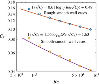
Friction factor
 $C_{f}=2\unicode[STIX]{x03C0}Nu_{\unicode[STIX]{x1D714}}J_{0}^{\unicode[STIX]{x1D714}}\unicode[STIX]{x1D708}^{-2}/Re_{i}^{2}$
as a function of the inner cylinder Reynolds number
 $Re_{i}$
, where
 $J_{0}^{\unicode[STIX]{x1D714}}=2\unicode[STIX]{x1D708}r_{o}^{2}r_{i}^{2}\unicode[STIX]{x1D714}_{i}/(r_{o}^{2}-r_{i}^{2})$
is the angular velocity current at the purely azimuthal laminar state. The circles denote the data extracted from DNS for our current rough–smooth (RS) wall cases, and the squares the data for smooth–smooth (SS) wall cases from Ostilla-Mónico et al. (Reference Ostilla-Mónico, van der Poel, Verzicco, Grossmann and Lohse2014a
,Reference Ostilla-Mónico, van der Poel, Verzicco, Grossmann and Lohse
b
), respectively. The lines show the best fits of the Prandtl–von Kármán law
 $1/\sqrt{C_{f}}=a\text{log}_{10}(Re_{i}\sqrt{C_{f}})+b$
, with
 $a=0.61$
,
 $b=0.49$
for RS cases and
 $a=1.56$
,
 $b=-1.63$
for SS cases.

At the inner cylinder rough boundary, the law of the wall is extended to incorporate roughness. Because of the pressure forces dominance,
 $\unicode[STIX]{x1D6FF}_{\unicode[STIX]{x1D708}}$
is no longer the relevant parameter. Instead, the roughness scale
 $h$
should be used to normalize the wall distance (Pope Reference Pope2000). With this change, the log law with roughness in the fully rough regime (Nikuradse Reference Nikuradse1933; Pope Reference Pope2000) becomes
 $$\begin{eqnarray}\displaystyle u^{+}=\frac{1}{\unicode[STIX]{x1D705}}\ln \left(\frac{y}{h}\right)+B, & & \displaystyle\end{eqnarray}$$
to be compared with (3.3). In figure 4(c), above the roughness height, there is a region (
 $0.1<y/h<0.16$
) where the velocity profiles collapse very well and show the logarithmic behaviour (3.4), with the von Kármán prefactor. The von Kármán constant
 $\unicode[STIX]{x1D705}$
stays the same while the fit for
 $B$
gives
 $B=3.2$
, exactly the same as found in rough channel flow (Ikeda & Durbin Reference Ikeda and Durbin2007).
3.3 Skin friction factor
An alternative way to describe the global transport properties is through the friction factor
 $C_{f}$
as a function of the inner cylinder Reynolds number
 $Re_{i}$
, as shown in figure 5. The Prandtl–von Kármán skin friction law (Schlichting Reference Schlichting1979; Lewis & Swinney Reference Lewis and Swinney1999; Pope Reference Pope2000; van den Berg et al.
Reference van den Berg, Doering, Lohse and Lathrop2003), which is an extension of the log law of the wall, is used to fit our data. The implicit form is
 $$\begin{eqnarray}\displaystyle \frac{1}{\sqrt{C_{f}}}=a\log _{10}(Re_{i}\sqrt{C_{f}})+b. & & \displaystyle\end{eqnarray}$$
For the smooth–smooth (SS) wall case, we get
 $a=1.56$
and
 $b=-1.63$
. This differs from the value of
 $a$
from turbulent channel (
 $a=1.91$
, see Zanoun, Nagib & Durst Reference Zanoun, Nagib and Durst2009) or pipe flows (
 $a=1.92$
, see McKeon, Zagarola & Smits Reference McKeon, Zagarola and Smits2005), due to the effects of curvature and large scale Taylor rolls, which make the von Kármán constant slightly larger in TC flow (Huisman et al.
Reference Huisman, Scharnowski, Cierpka, Kähler, Lohse and Sun2013; Ostilla-Mónico et al.
Reference Ostilla-Mónico, van der Poel, Verzicco, Grossmann and Lohse2014a
). The best fit for the current rough–smooth (RS) wall case results in
 $a=0.61$
and
 $b=0.49$
. Compared to
 $a=1.56$
in TC turbulence with the SS wall, here for RS cases
 $a$
is much smaller. It is important to note that on the one hand, the velocity profile for the RS cases is a combination of smooth wall (3.3) and rough wall (3.4) situations, on the other hand, the logarithmic term of (3.4) is independent of
 $Re_{i}$
. Therefore, the dependence of
 $C_{f}$
on
 $Re_{i}$
weakens for the RS cases as compared to the SS cases.
Ratio
 $\unicode[STIX]{x1D712}$
between the angular velocity drop of the smooth wall and the rough wall as a function of
 $Ta$
. The dashed line shows the trend of the asymmetry, which increases with increasing
 $Ta$
.

3.4 Asymmetry velocity profiles between smooth and rough walls
As stated before, we find the velocity profiles biased towards the rough wall. The lager
 $Ta$
is, the more asymmetric the velocity profile is. To quantify this, a asymmetry parameter
 $\unicode[STIX]{x1D712}$
is introduced, defined as
 $$\begin{eqnarray}\displaystyle \unicode[STIX]{x1D712}=\frac{\unicode[STIX]{x1D714}_{m}}{\unicode[STIX]{x1D714}_{i}-\unicode[STIX]{x1D714}_{m}}. & & \displaystyle\end{eqnarray}$$
Here,
 $\unicode[STIX]{x1D714}_{m}$
is the angular velocity at the middle gap. To repeat symmetry, one would have
 $\unicode[STIX]{x1D712}=1$
. The numerically obtained values of
 $\unicode[STIX]{x1D712}$
as function of
 $Ta$
is shown in figure 6. By using one rough wall and one smooth wall, we can compare the transport properties of different walls within the same flow configuration. This has been done in RB flow by Tisserand et al. (Reference Tisserand, Creyssels, Gasteuil, Pabiou, Gibert, Castaing and Chillà2011) and Wei et al. (Reference Wei, Chan, Ni, Zhao and Xia2014). Similarly for TC flow, if assuming that a symmetric cell has two independent smooth walls behaving the same as our outer cylinder, we get the difference of angular velocity across the gap as
 $2\unicode[STIX]{x1D714}_{m}$
. Thus, the smooth wall Nusselt number is
 $$\begin{eqnarray}\displaystyle Nu_{s}=\frac{Nu_{\unicode[STIX]{x1D714}}\unicode[STIX]{x1D714}_{i}}{2\unicode[STIX]{x1D714}_{m}}=\frac{Nu_{\unicode[STIX]{x1D714}}}{2}\left(\frac{1+\unicode[STIX]{x1D712}}{\unicode[STIX]{x1D712}}\right), & & \displaystyle\end{eqnarray}$$
and the corresponding smooth wall Taylor number
 $Ta_{s}$
is
 $$\begin{eqnarray}\displaystyle Ta_{s}=\frac{4Ta\unicode[STIX]{x1D714}_{m}^{2}}{\unicode[STIX]{x1D714}_{i}^{2}}=\frac{4Ta\unicode[STIX]{x1D712}^{2}}{(1+\unicode[STIX]{x1D712})^{2}}, & & \displaystyle\end{eqnarray}$$
both restore to the symmetric case for
 $\unicode[STIX]{x1D712}=1$
. For the rough boundary, a rough wall Nusselt number is defined as
 $$\begin{eqnarray}\displaystyle Nu_{r}=\frac{Nu_{\unicode[STIX]{x1D714}}\unicode[STIX]{x1D714}_{i}}{2(\unicode[STIX]{x1D714}_{i}-\unicode[STIX]{x1D714}_{m})}=\frac{Nu_{\unicode[STIX]{x1D714}}}{2}(1+\unicode[STIX]{x1D712}), & & \displaystyle\end{eqnarray}$$
with its rough wall Taylor number
 $$\begin{eqnarray}\displaystyle Ta_{r}=\frac{4Ta(\unicode[STIX]{x1D714}_{i}-\unicode[STIX]{x1D714}_{m})^{2}}{\unicode[STIX]{x1D714}_{i}^{2}}=\frac{4Ta}{(1+\unicode[STIX]{x1D712})^{2}}, & & \displaystyle\end{eqnarray}$$
again, both restore to symmetric case for
 $\unicode[STIX]{x1D712}=1$
. It is easy to find that
 $$\begin{eqnarray}\displaystyle Nu_{r}=\unicode[STIX]{x1D712}Nu_{s}, & & \displaystyle\end{eqnarray}$$
and
 $$\begin{eqnarray}\displaystyle Ta_{r}=\frac{Ta_{s}}{\unicode[STIX]{x1D712}^{2}}. & & \displaystyle\end{eqnarray}$$
Note that from figure 6 a rather linear growth of
 $\unicode[STIX]{x1D712}$
over two decades of
 $Ta$
is found, which would surely make the effective scalings between
 $Nu_{s}$
versus
 $Ta_{s}$
and
 $Nu_{r}$
versus
 $Ta_{r}$
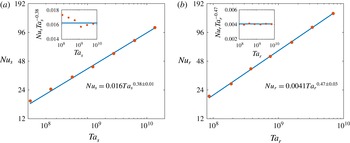
different. As a confirmation, in figure 7,
 $Nu_{s}$
versus
 $Ta_{s}$
and
 $Nu_{r}$
versus
 $Ta_{r}$
are shown. For the smooth wall, a clear scaling of
 $Nu_{s}\propto Ta_{s}^{0.38\pm 0.01}$
is revealed, which is in excellent agreement with the case where both walls are smooth and corresponds to the effective scaling of ultimate regime with logarithmic correction (van Gils et al.
Reference van Gils, Huisman, Bruggert, Sun and Lohse2011; Grossmann & Lohse Reference Grossmann and Lohse2011; Huisman et al.
Reference Huisman, van Gils, Grossmann, Sun and Lohse2012). This indicates that the rough wall cannot affect the scaling of the smooth wall, even in the ultimate regime. In contrast, the rough wall results show a scaling of
 $Nu_{r}\propto Ta_{r}^{0.47\pm 0.03}$
, which is very close to the
 $1/2$
scaling proposed by Kraichnan (Reference Kraichnan1962), corresponding to the pure ultimate regime without logarithmic correction. The competition between the smooth and rough walls eventually determines the global scaling exponent to be 0.42.
(a) Smooth wall Nusselt number
 $Nu_{s}$
as a function of smooth wall Taylor number
 $Ta_{s}$
. (b) Rough wall Nusselt number
 $Nu_{r}$
as a function of rough wall Taylor number
 $Ta_{r}$
. The bullets are the calculated
 $Nu_{s}$
and
 $Nu_{r}$
from simulations while the straight lines are the best fits
 $Nu_{s}=0.016Ta_{s}^{0.38\pm 0.01}$
for the smooth wall and
 $Nu_{r}=0.0041Ta_{r}^{0.47\pm 0.03}$
for the rough wall. The insets show the corresponding compensated plots.

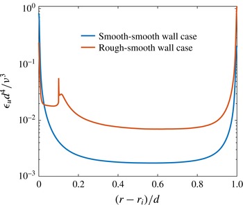
Dimensionless averaged energy dissipation rate
 $\unicode[STIX]{x1D716}_{u}d^{4}/\unicode[STIX]{x1D708}^{3}$
distribution along the radial direction at the current RS case in comparison with the SS case at
 $Ta=4.6\times 10^{9}$
. The dissipation is greatly enhanced at the bulk while decreased close to the rough boundary in the RS case as compared to the SS case.

Instantaneous axial vorticity field for
 $Ta=4.64\times 10^{9}$
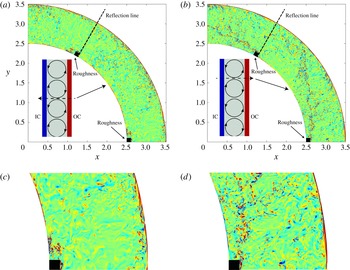
at two heights for the current inner rough wall case. The insets show schematic sketches of Taylor rolls in the meridional plane. The dashed lines denote where the cross-section contour plots are intercepted. The arrows on the dashed lines show the directions of the radial velocities. (a) At the height where Taylor roll is circulating from the outer to the inner cylinder. (b) At the height where Taylor roll is moving from the inner to the outer cylinder. Vortex shedding is found at the top of the rough element due to flow separation either to the back of the rough element (a) or to the bulk (b). Note that the reflection lines are used to show the regions beyond the computation domain. Abbreviations: IC (inner cylinder) and OC (outer cylinder). (c) Enlargement the near wall region for (a). (d) Enlargement of the near-wall region of (b).

3.5 Energy dissipation rate
Like RB flow, in TC flow an exact relation between the mean kinetic energy dissipation
 $\unicode[STIX]{x1D716}_{u,m}$
and the driving force
 $Ta$
holds, expressed as (Eckhardt et al.
Reference Eckhardt, Grossmann and Lohse2007b
)
 $$\begin{eqnarray}\displaystyle \unicode[STIX]{x1D716}_{u,m}=\unicode[STIX]{x1D708}^{3}d^{-4}Ta(Nu_{\unicode[STIX]{x1D714}}-1)\left(\frac{\sqrt{\unicode[STIX]{x1D702}}}{(1+\unicode[STIX]{x1D702})/2}\right)^{8}. & & \displaystyle\end{eqnarray}$$
Here we show how the inner wall roughness alters the kinetic energy dissipate rate distribution along the radial direction and thus increases the scaling exponent. Again due to the pressure dominance, the dissipation at the rough wall is decreased significantly as compared to the smooth wall case where the shear rate at the wall is extremely large. These effects redistribute the energy dissipation rate along the radius. Figure 8 details the comparison of the energy dissipation rate distribution along the radius in our current RS and SS cases at
 $Ta=4.64\times 10^{9}$
. Applying the Grossmann–Lohse theory (Grossmann & Lohse Reference Grossmann and Lohse2000, Reference Grossmann and Lohse2001) here, we separate the energy dissipation rate as boundary layer and bulk contributions. The more the bulk is dominant, the larger the scaling exponent is (Grossmann & Lohse Reference Grossmann and Lohse2004). The boundary layer thickness is estimated by
 $\unicode[STIX]{x1D706}/d=1.058/(2Nu_{\unicode[STIX]{x1D714}})$
for the current radius ratio (Brauckmann & Eckhardt Reference Brauckmann and Eckhardt2013). For
 $Ta=4.64\times 10^{9}$
, it is found that at the case with both smooth walls, the two boundary layers contribute 65 % of the total dissipation while the bulk contributes 35 %. With the rough inner wall, the dissipation generated below the height of the rough element only contributes 11 % to the total dissipation and the outer smooth boundary generates 26 %. Thus the bulk contributes 63 %. Therefore, in contrast to the smooth case, TC turbulence with inner rough wall is more bulk dominant and hence the torque scaling exponent is increased.
3.6 Vorticity field
To shed further light on how roughness pushes the dissipation into the bulk, in figure 9, we show the instantaneous axial vorticity field for
 $Ta=4.64\times 10^{9}$
at two sections: one for the Taylor rolls producing a current from inner to the outer cylinder and the other in the opposite direction. It is found that, due to the smaller shear rate, very few vortices are generated at the surfaces behind the rough elements compared to the smooth wall. Instead, flow separations at the top of the rough elements cause vortex shedding from it. These shed vortices are then transported by Taylor rolls either to the outer cylinder, which enhance dissipation in the bulk region, or to the cavities between the rough elements at the inner cylinder, which contribute to the dissipation in the near-wall region as well. That explains why although the shear rate is decreased significantly, the dissipation below the height of the rough element still contributes 11 % of the total.
4 Conclusion
In summary, we have performed DNS of TC turbulence with inner rough wall. It is found that the wind Reynolds number scales as
 $Re_{w}\propto Ta^{0.50\pm 0.01}$
, in accordance with the prediction by Grossmann & Lohse (Reference Grossmann and Lohse2011) for smooth boundaries. The angular velocity flux is found to have an effective scaling of
 $Nu_{\unicode[STIX]{x1D714}}\propto Ta^{0.42\pm 0.01}$
, which is a notably higher effective exponent than the ultimate regime value 0.38 seen for smooth walls. Furthermore, the dominant torque at the rough boundary stems from the pressure forces on the side faces of the rough element, rather than from viscous stresses. As a consequence, the law of the wall at the rough boundary depends on the roughness height, rather than the viscous length scale. By separating the torque into the smooth and rough walls contributions, we find that the smooth wall torque scaling follows
 $Nu_{s}\propto Ta_{s}^{0.38\pm 0.01}$
, the same as with both smooth walls. In contrast, the rough wall scaling follows
 $Nu_{r}\propto Ta_{r}^{0.47\pm 0.03}$
, close to the pure ultimate scaling
 $Nu_{\unicode[STIX]{x1D714}}\propto Ta^{1/2}$
. Lastly, the wall value of the energy dissipation rate decreases due to the smaller shear rate at the rough boundary while dissipation is redistributed through vortex shedding into the bulk. The system becomes bulk dominant, thus reducing the logarithmic correction and increasing the effective torque scaling exponent.
Note that the scaling exponent increase is only possible as the pressure contribution dominates the torques. Therefore it is interesting to try different spacings among the rough elements for either pressure or viscous force dominance. By doing so we may be able to control the torque scaling exponent in TC turbulence. Finally, a subsequent study of TC turbulence with both rough walls now seems mandatory in order to show whether the pure ultimate scaling
 $Nu_{\unicode[STIX]{x1D714}}\propto Ta^{1/2}$
without logarithmic correction is achievable or not.
Acknowledgements
We thank R. Verschoof for valuable discussions. This work is supported by FOM and MCEC, both funded by NWO. We thank the Dutch Supercomputing Consortium SurfSARA, the Italian supercomputer FERMI-CINECA through the PRACE Project No. 2015133124 and the ARCHER UK National Supercomputing Service through the DECI Project 13DECI0246 for the allocation of computing time.