1. Introduction
Nowadays, spray-painting robots are gradually replacing manual spraying in the furniture industry. With customization, multi-variety and small batch becoming the mainstream trend in the production of furniture, the production flexibility of spray-painting robot is required [Reference Wu, Wang, Zhang and Huang1]. Due to the needs of the spraying process, the programming of the robot becomes a complex and time-consuming process, and the low adaptability of the spray-painting robot to the rapidly changing production scenarios has hindered its large-scale use in small and medium-sized enterprises. The lead-through programming (LTP) approach [Reference Pan, Polden, Larkin, Van Duin and Norrish2, Reference Burghardt, Szybicki, Gierlak, Kurc, Pietruś and Cygan3], in which an operator guides the robot to program by hand, undoubtedly helps to increase programming speed and reduce programming complexity.
Common methods to achieve robot compliance control: The classification is mainly based on whether additional sensors are needed, among which impedance control and admittance control are divided according to the output variables of the controller [Reference Song, Yu and Zhang29].

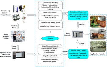
With the development of mechanism, industrial robots mainly have two configurations: parallel [Reference Wu, Zhang and Wang4–Reference Li, Zi, Zhou, Zhao and Ge7] and series [Reference Pan, Polden, Larkin, Van Duin and Norrish2]. Because of the large working space and simple configuration of series structure, it is the most widely used in spraying field. In this paper, the series manipulator is taken as an example to carry out the research on the lead-through teaching. To make it convenient and fast for operators to freely drag robots for trajectory programming, researchers have done a lot of research work and put forward a series of lead-through teaching methods. According to the requirements of advanced sensors and the access of robot control system, the existing methods to realize robot lead-through teaching are roughly divided into two categories: One is the position-based teaching method using vision sensors, force sensors and other devices, and the other is the torque-based teaching method using robot dynamics model and advanced control methods (the positions and torques method mentioned in this paper refer to the types of signals generated by the implementation scheme to be sent to the robot control system). See Fig. 1 for the classification of robot lead-through teaching methods. The position-based teaching method uses advanced sensor system to directly generate the reference position signal of robot joint and send it to the industrial robot controller. This kind of teaching method usually only requires the robot system to open the position control interface (opening the position/velocity loop and accepting position/velocity commands from outside is now the most common type of control system in industrial robots [Reference Brogårdh8, Reference Nilsson and Johansson9]). The most common control scheme is the admittance control of free robot dragging in Cartesian space based on the end force sensor and admittance model to directly generate the desired trajectory of the robot joint [Reference Fu and Li10–Reference Mujica, Crespo, Benoussaad, Junco and Fourquet13]. In addition, in refs. [Reference Ali and Atia14–Reference Zhang, Wang and Xiong16], researchers use visual equipment to capture the motion trajectory of the operator’s teaching device and combine the mapping algorithm of master-slave position relationship to realize the teaching programming without human contact. In refs. [Reference Ott, Ott, Kugi and Hirzinger17, Reference Keppler, Lakatos and Ott18] and other literatures, various robots have been designed by introducing force/torque sensors or compliant joints, but the vast majority of industrial spray-painting robots are not equipped with these hardware, and adding force/torque sensors to standard industrial robots is a rather expensive and difficult. Clearly, the advantage of this kind of lead-through teaching method based on position control is that it does not need to modify the robot control system structure, but cannot avoid the extra sensor configuration which greatly increases the cost and complexity of fast programming of the robot.
The torque-based teaching method realizes the compensation of gravity, inertia force and friction force by establishing an accurate robot dynamics model, so as to reduce the external force required by the operator in the process of dragging the robot [Reference Ragaglia, Zanchettin, Bascetta and Rocco19–Reference Zeng, Xiao and Liu21] or generate the joint torque control signal based on the expected impedance characteristics of the robot designed by the user through methods similar to impedance control [Reference Ott, Albu-Schaffer, Kugi and Hirzinger22–Reference Kana, Tee and Campolo24], so that the robot can performance a certain degree of flexibility to realize the robot lead-through teaching work. In refs. [Reference Sadeghian, Villani, Keshmiri and Siciliano25] and [Reference Sadeghian, Keshmiri, Villani and Siciliano26], estimates based on external torque are used as inputs for impedance and admittance control strategies to achieve sensorless compliance control. The core idea of realizing sensorless real-time estimation of external forces (or torque caused by these forces) is to rely on residual calculation based on the generalized momentum of the manipulator ([Reference De Luca and Mattone27], [Reference Erden and Tomiyama28]). Although several force/torque estimation strategies have been developed to avoid the use of dedicated sensors, the possibility of applying these strategies to the LTP has not been explored. Besides, this kind of torque-based teaching method requires the robot control system to open the torque control interface (for robots used in academic research, open torque control interface is very common, but in practical industrial applications, from the perspective of safety, robot manufacturers will not open the torque control interface to users). Sensorless, accurate and safe LTP frameworks for spray-painting robots with closed control system in structured environments are still missing.
For a long time, the closure of industrial robot systems has been the gap between modern control methods and industrial applications. To solve this problem, an adaptive radial basis function neural network external controller is proposed in ref. [Reference Ahanda, Aba, Melingui, Zobo and Merzouki30], which eliminates the influence of the internal controller in closed-loop control by approximating the internal controller, without knowing the specific internal control scheme. Liang proposed an adaptive image space visual servoing strategy which do not need joints and visual acceleration measurement, the strategy can deal with the camera’s internal and external parameters and the parameters of the motor dynamics and kinematics and dynamics parameter uncertainty [Reference Liang, Wang, Chen and Liu31]. A. C. Leite et al. proposed a new adaptive controller for image tracking of the robot without using visual velocity when the internal and external parameters of the camera are not calibrated [Reference Leite32]. Both refs. [Reference Liang, Wang, Chen and Liu31] and [Reference Leite32] rely on the assumption that the inner servoing loop is fast enough or the modification of the inner controller structure. In order to realize the application of modern control theory in practical industrial robot system, refs. [Reference Wang, Ren, Cheah and Xie33, Reference Wang, Ren, Cheah, Xie and Lyu34] proposed a dynamic modularity approach to resolve this issue, and the proposed modular design method can achieve the application of the torque-based modern control method in closed control systems by generating the velocity or position commands of the low-level joint servo control loop without modifying the parameters of robot control system. On the basis of ref. [Reference Wang, Ren, Cheah, Xie and Lyu34], this paper carried out further research on the teaching programming realized by manually dragging the spray-painting robot without additional dedicated sensor hardware and considering the motion accuracy and the safety of the operator, which is undoubtedly an interesting research content in the field of spray-painting robot programming.
In this work, a zero-moment lead-through teaching method for an industrial spray-painting robot with a closed control system is studied. Different from service robots and cooperative robots, which mostly adopt direct drive integrated joints, industrial spraying robots have large structure size and usually adopt gear, chain and other transmission devices to achieve large torque output of joints. This structure will introduce greater friction torque in the process of robot joint movement. In order to estimate the joint friction torques accurately, a friction model based on static, Coulomb and viscous friction characteristics was established in this work. Sigmoid function was used to characterize the friction of the robot joint during the process from static to rotate comprehensively. An identification method is used to obtain the inertial and gravity parameters of the robot quickly, and the robot dynamics model under low speed is approximated. Aiming at the problem of spray-painting robot lead-through teaching for large-size workpiece, a zero-moment lead-through control strategy based on dynamic model was designed. The lead-through teaching was realized by dynamic compensation of robot dynamics without using additional sensors. Because the inner torque control loop of the robot is closed, the torque compensation based on the output of the control model cannot be directly sent to the inner control system of the robot. Under the premise that the inner control loop of the robot is closed, a user-designed outer loop adaptive controller is designed to generate joint position/velocity commands, which are directly sent to the robot’s inner control system to achieve the desired torque control.
The rest of this paper is organized as follows: Basic kinematics and dynamics models as well as related assumptions and conditions are given in Section 2. In Section 3, the friction model and gravity compensation method of the robot are presented, and the design scheme of model-based zero-moment control and joint position/velocity commands based on adaptive method is illustrated, besides the necessary proof is carried out. In Section 4, relevant experiments are carried out to verify the feasibility of the design scheme through the actual lead-through teaching experiment. Section 5 is the conclusion and some perspectives of this paper.
2. Manipulator kinematics and dynamics
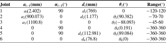
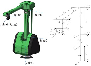
GR630ST is a typical 6-DOF serial spray-painting industrial robot. Each joint is driven by an independent motor. Figure 2 shows CAD model of robot and kinematics coordinate system. The calibrated kinematics parameters are shown in Table I.
The calibrated kinematics parameters.

CAD model of spray-painting robot and the coordinate system.

The dynamic model of the robot can be written as:
 \begin{equation} M\!\left(q\right)\!\ddot{q}+C\!\left(q,\dot{q}\right)\!\dot{q}+g\!\left(q\right)+\tau _{f}=Ki_{c} \end{equation}
where
 $M(q)\in R^{6\times 6}$
is the inertia matrix,
 $C(q,\dot{q})\in R^{6\times 6}$
is the Coriolis and centrifugal matrix,
 $g(q)\in R^{6}$
is the gravitational torque,
 $\tau _{f}$
is friction torque.
 $i_{c}\in R^{6}$
is the motor current,
 $K\in R^{6\times 6}$
is constant diagonal positive definite matrix of drive gains.
Equation (1) has the following properties [Reference Spong, Hutchinson and Vidyasagar35]:
Propertie 1: The inertia matrix
 $M(q)$
is symmetric and uniformly positive definite and
 $\dot{M}(q)-2C(q,\dot{q})$
is skew-symmetric.
Propertie 2: The dynamics (1) depend linearly on a constant dynamic parameter vector
 $a_{d}$
,
 \begin{equation} M\!\left(q\right)\!\dot{\varsigma }+C\!\left(q,\dot{q}\right)\!\varsigma +B\varsigma +g\!\left(q\right)=Y_{d}\!\left(q,\dot{q},\varsigma,\dot{\varsigma }\right)\!a_{d} \end{equation}
where
 $Y_{d}(q,\dot{q},\varsigma,\dot{\varsigma })\in \mathrm{\mathbb{R}}^{n\times {n_{a}}}$
is the dynamic regressor matrix.
 $\varsigma$
is a differentiable vector,
 $a_{d}$
is dynamic parameter vector.
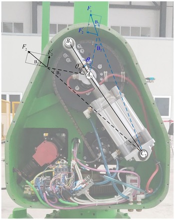
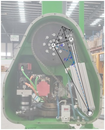
Compensation torque analysis of joint 2.

Compensation torque analysis of joint 3.

In order to meet the requirements of explosion-proof performance of the spraying robot from the perspective of structural design, the size of the driving motor of the joint 2 and 3 should not be too large, so auxiliary cylinders are installed. The installation position and structure of the cylinders are shown in the Figs. 3 and 4. In order to facilitate the follow-up work, the relationship between the cylinder driving torque
 $T_{2}, T_{3}$
and the cylinder pressure
 $P_{2}, P_{3}$
is given here.
As shown in Fig. 3, when the rotation angle of joint 2 is
 $\theta _{2}$
, the force provided by cylinder 2 is decomposed along the direction and vertical direction, and the following can be obtained
 \begin{equation} T_{2}=F'_{\!\!2}\left| A_{2}B_{2}\right| \end{equation}
Follows from the law of cosines
 \begin{equation} cos\!\left(\angle B_{2}A_{2}C_{2}\right)=\frac{\left| A_{2}B_{2}\right| ^{2}+\left| A_{2}C_{2}\right| ^{2}-\left| B_{2}C_{2}\right| ^{2}}{2\!\left| A_{2}B_{2}\right|\! \left| A_{2}C_{2}\right| } \end{equation}
We can get
 \begin{equation} \left| B_{2}C_{2}\right| =\sqrt{\left| A_{2}B_{2}\right| ^{2}+\left| A_{2}C_{2}\right| ^{2}-2\left| A_{2}B_{2}\right| \!\left| A_{2}C_{2}\right| cos\!\left(\angle B_{2}A_{2}C_{2}\right)} \end{equation}
And,
 \begin{equation} \frac{\left| B_{2}C_{2}\right| }{sin\!\left(\angle B_{2}A_{2}C_{2}\right)}=\frac{\left| A_{2}C_{2}\right| }{sin\!\left(\angle A_{2}B_{2}C_{2}\right)} \end{equation}
 \begin{equation} F'_{\!\!2}=F_{2}\!\left| A_{2}C_{2}\right| \frac{sin\!\left(\angle B_{2}A_{2}C_{2}\right)}{\left| B_{2}C_{2}\right| } \end{equation}
Namely,
 \begin{align} F_{2} &= \frac{T_{2}}{\left| A_{2}B_{2}\right| }\frac{1}{\left| A_{2}C_{2}\right| }\frac{\left| B_{2}C_{2}\right| }{sin\!\left(\angle B_{2}A_{2}C_{2}\right)} \nonumber \\[5pt] & =\frac{T_{2}\sqrt{\left| A_{2}B_{2}\right| ^{2}+\left| A_{2}C_{2}\right| ^{2}-2\left| A_{2}B_{2}\right| \! \left| A_{2}C_{2}\right| cos\!\left(\pi -\theta _{2}\right)}}{\left| A_{2}B_{2}\right| \!\left| A_{2}C_{2}\right| sin\!\left(\pi -\theta _{2}\right)} \end{align}
The piston diameter of cylinder 2 is 0.1 m, then the piston area
 $S_{2}=7.854\times 10^{-3}\,{\rm m}^{2}$
, and we can have
 \begin{equation} P_{2}=\frac{F_{2}}{S_{2}} \end{equation}
Namely,
 \begin{equation} T_{2}=\frac{P_{2}S_{2}\left| A_{2}B_{2}\right| \! \left| A_{2}C_{2}\right| sin\!\left(\pi -\theta _{2}\right)}{\sqrt{\left| A_{2}B_{2}\right| ^{2}+\left| A_{2}C_{2}\right| ^{2}-2\left| A_{2}B_{2}\right| \! \left| A_{2}C_{2}\right| cos\!\left(\pi -\theta _{2}\right)}} \end{equation}
where
 $| A_{2}B_{2}|$
= 0.125 m,
 $| A_{2}C_{2}|$
= 0.335 m.
Similarly, the driving force
 $F_{3}$
of cylinder 3 is solved. when the rotation angle of joint 2 is
 $\theta _{3}$
, we have
 \begin{equation} F_{3}=\enspace \frac{T_{3}}{\left| A_{3}B_{3}\right| cos\!\left(\theta _{3}\right)} \end{equation}
where
 $| A_{3}B_{3}|$
= 0.1 m.
Similar to
 $T_{2}$
, we have
 \begin{equation} \mathrm{T}_{3}=P_{3}S_{3}\left| A_{3}B_{3}\right| cos\!\left(\theta _{3}\right) \end{equation}
3. Controller design
3.1. Model identification
3.1.1. Friction model
Traditional friction model includes Coulomb friction, viscous friction and static friction. According to the joint velocity of the robot, the state of the robot is divided into three kinds [Reference Lee, Kim and Song36]:
 \begin{equation} \tau _{f}=\left\{\begin{array}{l} \tau _{c}\;\mathrm{sgn}\!\left(i_{c}\right)\!,\left| \dot{q}\right| \lt\! \varepsilon,\dot{q}_{d}=0\\[5pt] \tau _{s}\;\mathrm{sgn}\!\left(i_{c}\right)\!,\left| \dot{q}\right| \lt \! \varepsilon,\dot{q}_{d}\neq 0\\[5pt] \tau _{c}\;\mathrm{sgn}\!\left(i_{c}\right)+\tau _{v}\!\left(\dot{q}\right)\!,\left| \dot{q}\right| \geq \varepsilon \end{array}\right. \end{equation}
which
 $\tau _{c}$
,
 $\tau _{s}$
,
 $\tau _{v}$
is coulomb, static friction and viscous friction components,
 $i_{c}$
is the motor current,
 $\dot{q}_{d}$
is the motor speed required for the corresponding joint.
 $\varepsilon$
is the critical speed value for transition to the operating state. However, this model cannot well represent the nonlinear characteristics of friction. Therefore, another method is proposed to simulate the rotational angle-dependent characteristics of friction in harmonic drive by describing the low-speed fluctuation and steady-state Coulomb friction and viscous friction through the second-order Fourier series [Reference Xiao, Zhang, Hong, Wang and Zeng37]. The friction force of joint
 $i$
is expressed as
 \begin{equation} \begin{array}{l} \tau _{fi}=f_{i1}\sin \!\left(q_{i}\right)+f_{i2}\cos \!\left(q_{i}\right)+f_{i3}\sin \!\left(2q_{i}\right)\\[5pt] +\;f_{i4}\cos \!\left(2q_{i}\right)+f_{ic}\sin \!\left(q_{i}\right)+f_{is}e^{-{f_{ti}}{\dot{q}_{i}}}\;\mathrm{sgn}\!\left(q_{i}\right)+f_{iv}\dot{q}_{i} \end{array} \end{equation}
which
 $q_{i}, \dot{q}_{i}$
is the position and velocity of joint
 $i,\, f_{i1}\sim f_{i4}$
is the Fourier friction coefficient,
 $\;f_{ic}\;\; f_{is}\;\; f_{iv}$
are coulomb, static friction and viscous friction coefficients, respectively,
 $f_{ti}$
is the transition index from rest to motion.
The friction model used in this paper combines Eqs. (13) and (14) with static friction estimation. The model uses Fourier series to represent the low-speed fluctuations of joint rotation, the static friction component that depends on the direction of the motor current and the friction during the transition period (the static torque between joint motions) by using the Sigmoid function. Then, the friction model of joint
 $i$
is:
 \begin{equation} \begin{array}{l} \tau _{fi}=\tau _{si}\;\mathrm{sgn}\!\left(i_{c}\right)S^{-1}\!\left(\dot{q}_{i}\right)+\\[7pt] \!\left(f_{i1}\sin \!\left(\dfrac{q_{i}}{R_{i}}\right)+f_{i2}\cos \!\left(\dfrac{q_{i}}{R_{i}}\right)+f_{i3}\sin \!\left(\dfrac{2q_{i}}{R_{i}}\right)+f_{i4}\cos \!\left(\dfrac{2q_{i}}{R_{i}}\right)+\tau _{ci}\right)\\[11pt] \times\; \mathrm{sgn}\!\left(\dot{q}\right)+\left(\,f_{5}\sin \!\left(q_{i}\right)+f_{6}\cos \!\left(q_{i}\right)+\tau _{v1i}\dot{q}+\tau _{v2i}\dot{q}^{2}\right)S\!\left(\dot{q}_{i}\right) \end{array} \end{equation}
where
 $\tau _{si} \tau _{ci}$
is static and Coulomb friction coefficient,
 $R_{i}$
is the ratio of each joint,
 $\tau _{v1i}\; \tau _{v2i}$
is the coefficient of viscous friction,
 $f_{i1}\sim f_{i6}$
is the Fourier friction coefficient, and
 \begin{equation} S\!\left(\dot{q}_{i}\right)=\frac{1}{1+e^{-\frac{\dot{q}_{i}}{\dot{q}_{i\varepsilon }}}} \end{equation}
 \begin{equation} S^{-1}\!\left(\dot{q}_{i}\right)=e^{-\frac{\dot{q}_{i}}{\dot{q}_{i\varepsilon }}} \end{equation}
where
 $\dot{q}_{i\varepsilon }$
is the transition velocity.
3.1.2. Gravity and inertia identification
In order to achieve zero-moment lead-through teaching, robot dynamics parameters are needed. The traditional dynamic parameter identification method calculates the dynamic parameters of the robot through the data collection in the process of the robot moving under the optimized identification excitation trajectory combined with the optimized identification algorithm. In order to identify all the dynamic parameters, the most important part of the whole process is to design a reasonable identification trajectory. However, standard industrial inner controllers can only generate very simple trajectories (like line, circles, Point to Point, etc.), and this becomes an obstacle in the practical application of traditional parameter identification methods which optimized trajectories usually require to generate arbitrary joint motions.
The inertia matrix, gravity matrix and Coriolis matrix are decoupled by linearization of dynamic model (1), and the models related to inertia parameters are obtained, respectively. While the influence of Coriolis force is ignored, because the inertial matrix and gravity matrix are only related to the pose of the robot, and the robot runs slowly in the lead-through teaching process. So, the related terms of the inertia matrix and gravity matrix can be solved separately. Based on the two-step identification method proposed in ref. [Reference Grotjahn, Daemi and Heimann38], the dynamics parameters of the robot in (5) are divided into three parts:
(a) The gravitational parameters
 $a_{g}$
which only associated with gravity of robot
 $g(q)$
.
(b) The diagonal parameters
 $a_{Md}$
which only associated with the diagonal elements of inertia matrix
 $M(q)$
.
(c) The off-diagonal parameters
 $a_{Mod}$
which only associated with the off-diagonal elements of inertia matrix
 $M(q)$
.
Furthermore, typically the number of elements of
 $a_{Mod}$
is small due to the symmetric structure of the links. The grouping leads to a separation of regressor matrix
 $Y_{d}(q,\dot{q},\ddot{q})$
as
 \begin{equation} \tau =\underset{M\left(q\right)\ddot{q}}{\underbrace{Y_{Md}\!\left(q,\ddot{q}\right)\!a_{Md}+Y_{Mod}\!\left(q,\ddot{q}\right)\!a_{Mod}+Y_{Mg}\!\left(q,\ddot{q}\right)\!a_{g}}}+\underset{C\left(q,\dot{q}\right)\dot{q}}{\underbrace{Y_{c}\!\left(q,\dot{q}\right)\!a_{d}}}+\underset{g\left(q\right)}{\underbrace{Y_{g}\!\left(q\right)\!a_{g}}} \end{equation}
where
 $Y_{Md}$
and
 $Y_{Mod}$
are the regressor which only associated with the diagonal and off-diagonal elements of inertia matrix,
 $Y_{Mg}$
is the regressor which both associated with elements of inertia matrix and gravity matrix,
 $Y_{c}$
is the regressor which only associated with the elements of
 $C(q,\dot{q}), Y_{g}$
is the regressor which only associated with the elements of gravity matrix.
According to property 2, the inertia parameters of each link in the dynamic equation can be separated to realize the linearization of the dynamic model. For each link
 $i$
, the dynamic parameters include the mass of the link
 $m_{i}$
, the position of the center of mass
 $r_{i}=[x_{i},y_{i},z_{i}]^{T}$
and the inertia tensor
 $I_{i}$
which respect to the origin of the link coordinate system. Thus, we can regroup the dynamic parameters of each link as
 \begin{equation*} a_{i}=[m_{i},\,m_{i}x_{i},\,m_{i}y_{i},\,m_{i}z_{i},\,I_{xx}^{i},\,\,I_{xy}^{i},\,\,I_{xz}^{i},\,\,I_{yy}^{i},\,\,I_{yz}^{i},\,\,I_{zz}^{i}]^{\mathrm{T}} \end{equation*}
In general, not all link parameters affect the dynamics equation of the robot. For example, for link 1, only the inertia
 $I_{zz}$
is involved in the calculation of the dynamic model. In addition, due to the coupling effect between links, the dynamic parameters are not independent of each other, but linearly combined together, which leads to the existence of zero column elements and linearly correlated columns in the regression matrix
 $Y(\!\boldsymbol\cdot\!)$
. Recursive solution and numerical methods (such as QR [Reference Mamedov and Mikhel39] and SVD [Reference Gautier40] decomposition method) are commonly used to solve the singularity by reorganizing the linearly related columns in
 $Y(\!\boldsymbol\cdot\!)$
and removing the zero element columns to obtain a new regression matrix. Accordingly, the original dynamic parameters of the connecting rod are reassembled and removing the quantity that does not affect the dynamic output to obtain a new base parameter set
 $a_{b}$
. To be exact, the element in
 $a_{b}$
is the dynamic coefficient after linear combination, rather than the standard dynamic parameter [Reference Gaz, Flacco and De Luca41].
The measurement of gravitational torque must include long periods with constant velocity in order to excite gravity and eliminate inertial effects. The average torques of joint torque in forward and backward motion give the required gravitational torque. Acceleration accounts for a greater proportion of the motion used to identify the diagonal elements of inertia matrix.
When we get the gravity torque, we can use the least square method to get the corresponding gravity parameter
 $a_{g}$
[Reference Mamedov and Mikhel39]. We can use the same way as gravitational measurements to measure the off-diagonal elements of the inertia matrix. Joint
 $i$
is moved at a very low constant velocity, and joint
 $j$
is accelerated at the same time. Because the influence of Coriolis term is ignored in the experiment, there is an error between the final model and the actual one. Considering the uncertainty [Reference Zhou, Zi and Qian42] of the model,
 ${\Delta} (q,\dot{q},\ddot{q})$
is introduced and is required to satisfy
 $\| \!{\Delta} (q,\dot{q},\ddot{q})\| \leq \nu$
. In the experiment, we chose
 ${\Delta} (q,\dot{q},\ddot{q})=10\cdot \sin\!(t)$
, and
 $\nu =12$
.
3.2. Control strategy design
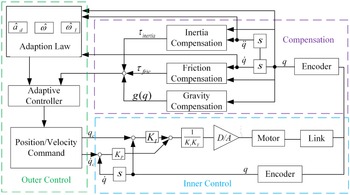
Ideally, our goal is to calculate the gravity, friction and inertia forces at each axis position and speed in real time during the robot operation, and then realize the robot balance by compensating each torque, so that the user only needs to overcome the Coriolis force to achieve the robot lead-through teaching. Since the inner torque control loop of the robot cannot be directly accessed by users, the joint velocity/position commands are designed by an adaptive method to achieve the output of target control torque. The control block diagram is shown in the Fig. 5.
Adaptive lead-through teaching control block diagram for closed control system of industrial robot.

For the spray-painting robot in this paper, an adaptive controller is designed considering the PI velocity controller used in the inner control loop:
 \begin{equation} i_{c}=-K_{P}\!\left(\dot{q}-\dot{q}_{c}\right)-K_{I}\!\left(q-q_{c}\right) \end{equation}
where
 $K_{P}, K_{I}$
are proportional and integral gains (positive definite diagonal matrices) respectively,
 $q_{c}$
and
 $\dot{q}_{c}$
are joint position and speed commands.
To solve the problem of measurement without joint torque sensor, we can take
 $Ki_{c}$
in (1) a s the “torque” input and our goal becomes
 \begin{equation} \tau =Ki_{c}=-KK_{P}\!\left(\dot{q}-\dot{q}_{c}\right)-KK_{I}\!\left(q-q_{c}\right)\rightarrow \tau _{d} \end{equation}
Define
 $K^{*}=KK_{P}=diag[k_{ii}^{*},i=1,\ldots,6]$
being positive constants. We defined the joint velocity command as
 \begin{equation} \dot{q}_{c}+\hat{\Upsilon}_{I}q_{c}=\dot{q}+\hat{\Upsilon}_{I}q+diag\!\left[\hat{\omega }\right]\!\tau _{d} \end{equation}
where
 $\hat{\Upsilon}_{I}$
is the estimate of
 $\Upsilon_{I}=K_{P}^{-1}K_{I}$
, which can be expressed as
 $\hat{\Upsilon}_{I}=diag[\hat{\omega }_{I}]$
. And
 $\hat{\omega }=[\hat{\omega }_{i},i=1,\ldots,6]^{T}$
denotes the scale weight is the estimate of
 $\omega =[k_{ii}^{\ast-1},i=1,\ldots,6]^{T}$
.
We then have that
 \begin{equation} \!\left(\dot{q}_{c}-\dot{q}\right)+\hat{\Upsilon}_{I}\!\left(q_{c}-q\right)=diag\!\left[\omega \right]\tau _{d}+diag\!\left[{\Delta} \omega \right]\tau _{d}-{\Delta} \hat{\Upsilon}_{I}\!\left(q_{c}-q\right) \end{equation}
where
 ${\Delta} \omega =\hat{\omega }-\omega =[\hat{\omega }_{i}-k_{ii}^{\ast-1},i=1,\ldots,6]^{T}$
, which leads us to obtain that
 \begin{equation} \tau =\tau _{d}+K^{*}diag\!\left[{\Delta} \omega \right]\tau _{d}-K^{*}\mathrm{{\Delta} \Upsilon}_{I}\!\left(q_{c}-q\right) \end{equation}
where
 $\mathrm{{\Delta} \Upsilon}_{I}=\hat{\Upsilon}_{I}-\Upsilon_{I}$
. By the joint velocity command proposed before, the closed-loop of robot dynamics become
 \begin{equation} M\!\left(q\right)\!\ddot{q}+C\!\left(q,\dot{q}\right)\!\dot{q}+g\!\left(q\right)+\tau _{f}=\tau _{d}+{\Delta} \tau _{d} \end{equation}
where
 \begin{equation*} {\Delta} \tau _{d}=\tau -\tau _{d}=K^{*}diag[{\Delta} \omega ]\tau _{d}-K^{*}\mathrm{{\Delta} \Upsilon}_{I}(q_{c}-q) \end{equation*}
To meet the requirements of the control model (24), the updating laws for
 $\hat{\omega }$
and
 $\hat{\omega }_{I}$
should be properly developed so that
 ${\Delta} \tau _{d}$
decays to zero. So, when we come to the adaptive method, we have
 \begin{equation} \hat{\tau }_{d}=\hat{M}\!\left(q\right)\!\ddot{q}+\hat{C}\!\left(q,\dot{q}\right)\dot{q}+\hat{g}\!\left(q\right)+\hat{\tau }_{f}=Y_{d}\!\left(q,\dot{q},\dot{q},\ddot{q}\right)\!\hat{a}_{d} \end{equation}
Then, we have
 \begin{equation} \hat{\tau }_{d}-\tau _{d}=Y_{d}\!\left(q,\dot{q},\dot{q},\ddot{q}\right){\Delta} a_{d}+K^{*}diag\!\left[\tau _{d}\right]{\Delta} \omega -K^{*}diag\!\left[q_{c}-q\right]{\Delta} \omega _{I} \end{equation}
Define
 \begin{equation} e=\hat{\tau }_{d}-\tau _{d} \end{equation}
Then, we have the adaptation law for
 $\hat{a}_{d}, \hat{\omega }, \hat{\omega }_{I}$
defined as
 \begin{equation} \dot{\hat{\omega }}=-{\Lambda} diag\!\left[\tau _{d}\right]\!e \end{equation}
 \begin{equation} \dot{\hat{a}}_{d}=-{\Gamma} _{d}Y_{d}^{T}\!\left(q,\dot{q},\dot{q},\ddot{q}\right)\!e \end{equation}
 \begin{equation} \dot{\hat{\omega }}_{I}=-{\Lambda} _{I}diag\!\left[q_{c}-q\right]\!e \end{equation}
where
 ${\Lambda}$
and
 ${\Lambda} _{I}$
are diagonal positive definite matrices, and
 ${\Gamma} _{d}$
is symmetric positive definite matrices. The advantage of joint velocity command given by (21) is included the dynamic influence which can be considered as scaled compensation in the model.
Suppose that
 $\hat{\Upsilon}_{I}$
is uniformly definite, then the adaptive outer loop controller given by (21) and (28)–(30) for the robot system (1) under the inner PI controller (19) ensures the stability of the system and convergence to the desired torque.
Proof :
Consider the Lyapunov function:
 \begin{equation} V=\frac{1}{2}\left[{\Delta} \omega ^{T}{\Lambda} ^{-1}K^{*}{\Delta} \omega +{\Delta} {a_{d}}^{T}{{\Gamma} _{d}}^{-1}{\Delta} a_{d}+{\Delta} {\omega _{I}}^{T}{{\Lambda} _{I}}^{-1}K^{*}{\Delta} \omega _{I}\right] \end{equation}
whose derivative
 $\dot{V}=-e^{T}e\leq 0$
. Thus, it can be shown that
 $\hat{a}_{d}\in L_{\infty }, \hat{\omega }\in L_{\infty }, \hat{\omega }_{I}\in L_{\infty }$
, and
 $e\in L_{2}$
. If
 $e$
is further uniformly continuous, we obtain that
 $e\rightarrow 0$
, that is,
 $\tau _{d}\rightarrow \hat{M}(q)\ddot{q}+\hat{C}(q,\dot{q})\dot{q}+\hat{g}(q)+\hat{\tau }_{f}$
as
 $t\rightarrow \infty$
. This is based on the properties of square-integrable and uniformly continuous functions.
It can be obtained from the above results that
 $\tau _{d}$
converges to
 $\tau =M(q)\ddot{q}+C(q,\dot{q})\dot{q}+g(q)+\tau _{f}$
in the sense of certainty equivalence [Reference Ciliz43]. In this way, we can use the standard deterministic equivalence principle to design the adaptive controller and can realize the application of torque-based control scheme when the internal control system of the robot is closed.
4. Experiments design and implementation
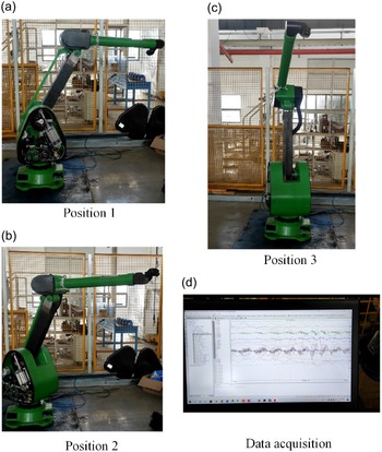
The robot can drag and teach the spraying track and monitor the tracking error. After the coordinate system is established, the calibrated kinematics parameters are shown in Table I. A teaching handle is installed at the end of the robot, and a six-dimensional force sensor is installed at the end to measure the force and torque applied by the operator in the teaching process. There are no external forces in the process of friction model identification, gravity and inertia measuring, and no relevant components are installed at the end of the robot. The experiment setup and data acquisition are shown in Fig. 6.
Joint friction, gravity and inertia identification experiment and data acquisition.

The parameter identification of friction, gravity and inertia provides the basis for the lead-through teaching experiment. According to the robot dynamics model (1), the output torque of the motor provides inertia force, Coriolis force and gravity after overcoming friction. When a single joint uniformly rotates at low speed, the influence of inertia force and Coriolis force can be ignored. Since at any position with the same joint angle, the gravity torque is equal while the friction force is equal and opposite, the two times friction force values at the same joint angle can be obtained by approximating the difference of the output torque of the two motors. Similarly, the sum of the output torques of two motors at the same joint angle is twice the magnitude of the gravity torques. After the joint friction model and gravity parameters are obtained, the inertial parameters can be obtained according to the identification method in Section 3.1.2.
Experiments are carried out according to the friction model established in Section 3.1.1. Because each joint friction model is independent, the parameters of each joint friction model can be identified separately. The drive gain
 $K=[46.2166.183911.1511.155.58]^{T}$
.
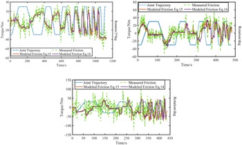
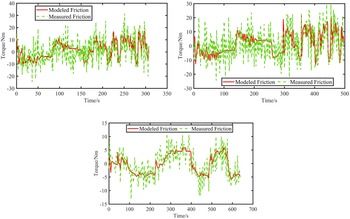
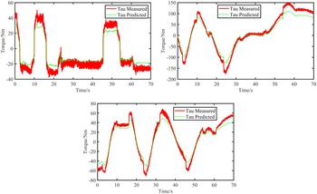
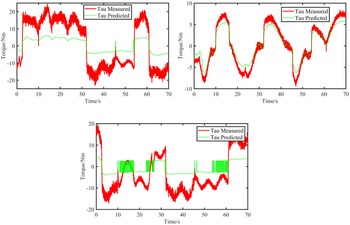
In the friction identification experiment, the angular velocity increment range of each joint is defined as 0.5-4 degrees/s for low-speed operation. Each joint reciprocates forward and backward over the range of joint motion, defining the joint trajectory in the initial and final 5% of the path following a constant velocity profile with parabolic mixing (constant acceleration). Define residence time for each end of the path which equal to the time of one-way joint movement. The joint trajectory is shown as blue dash line in Fig. 7 for the data fitting results of the joint friction model of joint 1 to joint 3, and Fig. 8 respectively shows the comparison results of the actual measured friction of robot joint with the model calculation. The measured friction torques were compared with those of the model, and the mean square error of the calculated joint friction model was in the range of 5-15 Nm. The large error of joint 1 to joint 3 is largely due to the large joint size and transmission, especially the spray-painting robot used in the experiment used a cylinder auxiliary device at joint 2 and joint 3 as an extra power input, which further increased the measurement error. Due to the smaller joint size and transmission ratio, joints 4-6 exhibit smaller torques and torque prediction errors. After the friction force, gravity and inertia force experiment, the robot dynamics model by ignoring Coriolis force is obtained. Meanwhile, the model results of Eq. (14) are compared with the model results of Eq. (15) in this paper. It can be seen from Fig. 7 that the trends of the two models are roughly the same, but the model in this paper can better simulate the friction force when the joint motion state changes, and the simulation effect is better than that of Eq. (14). Figures 9 and 10 show the actual measuring each joint torque and the torque-based on the model. It can be seen from the figure that there is a certain error between the estimated torque and the actual torque of each joint, which is caused by the error of friction model and ignoring the Coriolis force. But from the point of view of lead-through teaching, the model works.
Parameter fitting of robot joint friction model and joint motion trajectory of robot joint 1-3.

Compare between friction model and measurement results of robot joint 4-6.

Measured and estimated torques for joint 1-3.

Measured and estimated torques for joint 4-6.

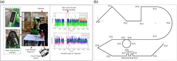
After the characterization, zero-moment control is adopted. When the robot switches to the lead-through teaching mode, the spraying operator can flexibly move in the robot workspace. The goal is to make the motion feel as free as possible so that the operator can easily guide the spray gun to follow the desired trajectory. Lead-through teaching experiment hardware and the operating force of end-effector collected during the experiment are shown in Fig. 11(a). According to the collaborative robot design standard ISO 15066, desired experimental trajectory is shown in Fig. 11(b). During the experiment, drag the end of the robot to move from point P10 to point P35 in turn. The designed adaptive controller parameters are chosen as
 ${\Gamma} _{d}=I_{36}, {\Lambda} =0.01I_{6}, {\Lambda} _{I}=0.02I_{6}$
, the initial value of
 $\hat{a}_{d}$
is set as
 $\hat{a}_{d}(0)=0_{36}$
, here we do not include the parameters associated with the friction and the base dynamic parameters of robot are obtained by QR decomposition method in ref. [Reference Leite32]. The initial value of
 $\hat{\omega }$
and
 $\hat{\omega }_{I}$
are chosen as
 $\hat{\omega }(0)=0_{6}$
, and
 $\hat{\omega }_{I}(0)=[1.2\;1.2\;1.2\;1.2\;1.2\;1.2]^{T}$
.
Lead-through teaching experiment setup and desired trajectory. (a) Experiment setup of lead-through teaching. (b) Desired trajectory of end-effector.

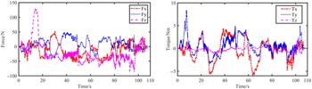
The force and torque of lead-through teaching based on power-off gravity compensation method.

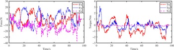
The force and torque of lead-through teaching based on adaptive method.

First of all, a lead-through teaching experiment based on gravity compensation method was carried out in the off-servo state. This scheme is a robot’s own scheme, which can realize partial gravity compensation by only two cylinders of the joint 2 and joint 3 when the servo power of each joint is cut off. As can be seen from Fig. 12, when the robot moves along the target trajectory, each movement inflection point corresponds to a larger resistance. On average, dragging the end of the robot along the target trajectory requires about 25 N of force to move the robot and much less force to move along a straight line. It is worth noting that the Z-force suddenly increases during the operation of the robot, and a higher force of 130 N is observed in the Z-direction, which is caused by the unstable cylinder pressure and the large error of the cylinder compensation model due to the gravity changes with the position during the operation.
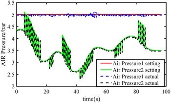
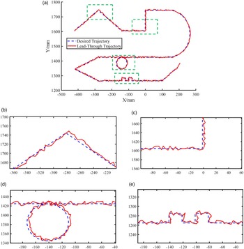
Figure 13 shows the operator force and torque in the lead-through teaching with low speed based on adaptive outer loop control in this paper. Ideally, when the robot is under model-based zero-moment control, the external force exerted by the operator during the lead-through teaching process should be close to zero. However, due to the friction model, gravity, inertia force error and the neglect of Coriolis force, the operator still needs to apply a certain amount of force during the dragging instruction process. The pressure change of the auxiliary cylinder in the corresponding lead-through teaching process is shown in Fig. 14. The actual cylinder pressure can follow the set pressure value well. As can be seen from Fig. 15, when the robot moves along the target trajectory, each movement inflection point still corresponds to a large force. On average, when the end of the robot moves along the target trajectory, the force required is about 15 N, which is significantly reduced compared with the original control scheme. The comparison between actual trajectory and desired trajectory in the teaching process based on the adaptive method is shown in Fig. 15. It can be seen that due to the lack of contact between the end-effector and the plane in the teaching process and the natural shaking of operator hands, the actual trajectory of the end-effector is not completely coincident with the desired trajectory, and the error is large at the inflection points of each trajectory. In general, the desired trajectory can be tracked well at low speed. Compared with the off-servo control, there is no sudden change in the operator force, and the operation process is more stable.
The cylinder pressure during the experiment of lead-through teaching.

Lead-through teaching trajectory comparison under adaptive control scheme: (a) shows the comparison between the actual drag trajectory and the target trajectory, and (b)-(e) shows a partially enlarged view.

5. Conclusion
In this paper, the zero-moment lead-through teaching control of an industrial spray-painting robot with a closed control system is studied. From the perspective of application, the existing controllers designed based on torque methods need to open the inner torque control loop of the robot and allow the user to modify the parameters of the inner loop controller according to the designed control law, but the actual situation is exactly the opposite. In order to realize the application of torque control method in the closed control system of industrial robots, this paper designs the robot joint speed/position control command based on the adaptive method. The scheme has a user-defined outer loop controller and an inner loop controller defined by the robot. Under the action of the proposed control command, it can realize the application of torque-based control method in robot with closed control system. In order to improve the application effect of zero-moment lead-through teaching, the friction model of robot joint was established by combining the parameters of the friction model with static, Coulomb and viscous friction characteristics, and using Sigmoid function to represent the transition between motion states. The experimental results show that the joint velocity/position command generated by the external loop controller designed based on the adaptive method can realize the application of torque-based control method in industrial robots with closed control system. This perspective might also help expand the road of nonlinear control theory toward commercial control systems.
Author contributions
Bin Zi conceived the formulations and the required mathematical methodology and then carried out the derivation procedure. Yajun Liu validated the formulations through the programming, drafted and revised the manuscript. Sen Qian and Zhengyu Wang coordinated the research and helped revised the manuscript. Lijun Jiang and Lei Zheng helped develop the experimental procedures and provided the robots and experiment sites.
Financial support
This work was supported by National Natural Science Foundation of China (Project Nos. 51925502 and 72188101).
Conflicts of interest
The authors declare no conflicts of interest exist.
Ethical approval
Not applicable.