1. INTRODUCTION
The plasma focus devices (PFDs) are in miniature and large sizes with less than 5 joules and energy up to mega joules (Soto et al., Reference Soto, Pavez, Tarifeño, Moreno and Veloso2010). The capacitor bank is discharged in the PFD during a few microseconds. The current between the anode and cathode, thereby discharging the capacitor bank, causes ionization of the gas. In all of these machines, the current sheath accelerates due to the Lorentz force and centralizes at the top of the anode (Lee & Saw, Reference Lee and Saw2013). Up to now, the strong induction variation by the kink and sausage instabilities after plasma pinch is known as the most important source of ion acceleration. Their reports are limited to ion energies up to hundreds of keV and are not able to justify the existence of ions with higher energies in the order of MeV (Lee & Saw, Reference Lee and Saw2013). Furthermore, none of the presented ion acceleration mechanisms could explain the ion collision with the top of the anode. In the following, a review of studies regarding ion acceleration and its angular distribution has been carried out. Bhuyan et al. (Reference Bhuyan, Chauqui, Farve, Mitchell and Wyndham2005) have expressed that the current re-distribution and the strong voltage due to the sudden variation of the induction in disruption phase of plasma focus formation leads to the ion escape during the plasma pinch phase. Mizuguchi et al. (Reference Mizuguchi, Sakai, Yousefi, Haruki and Masugata2007) have investigated the high energy proton acceleration by using the surfatron mechanism. They showed that the trapped proton in the electrostatic potential near the shock front can be accelerated up to MeV after the plasma pinch. In their study, the ring shape of the angular ion distribution and its decline on the central electrode axis was remarkable. The ion movement in the dense plasma column has been modeled by Pasternak and Sadowski in three dimensions (Pasternak & Sadowski, Reference Pasternak and Sadowski1998). In their study, the ion emission is assumed, such as jet-like strings. Moreover, the filamentary configuration is considered. Vahdat et al. produced N-13 radioisotope by hitting the energetic ions to the carbon as a target (Roshan et al., Reference Roshan, Lee, Lee, Talebitaher, Rawat and Springham2009). In addition to the upper wall of the PFD, they had some carbon on the top of the anode that became activated. They found that the ion with energy up to MeV should impact the top of the anode. This process was not justified by any of the proposed ion acceleration mechanisms. Yousefi et al. studied the ions energy spectrum and imaged the plasma pinch in a small PFD (Yousefi et al., Reference Yousefi, Nakata, Ito and Masugata2007). They showed that the most energetic ions dealt with the CR39 track detector in near-zero angles with respect to the axis of the device. Moreover, the ions energy reduced with a distance from the zero degree. As can be seen from the mentioned studies, the sudden change in the plasma induction in the dense plasma column is given as a consequence of the ion acceleration after its disruption due to the sausage instability. Moreover, two experimental phenomena include ion acceleration up to MeV and the cause of the ring angular distribution of ions that have not been presented simultaneously yet. In the present study, the reasons for the existence of the ions with several MeV energies and justification of the ion energy spectrum as well as presentation of ion angular distribution and its trajectory are considered. For these purposes, the 4.5 kJ Mather type PFD with capacitor voltage of 15 kV and capacitance of 40 µf are simulated by COMSOL Multiphysics (Baghdadi et al., Reference Baghdadi, Amrollahi, Habibi and Etaati2011). Kasperczuk et al. (Reference Kasperczuk, Paduch, Tomaszewski, Zielinska, Miklaszewski and Szymaszek2016) presented a test of a plasma focus (PF) device as a metallic plasma jet generator. The eroded copper (Cu) plasma, swept by the deuterium plasma sheath to create the metallic plasma jet. successful adaptation of the PF device to the metallic plasma jet generator was reported. Sadeghi et al. (Reference Sadeghi, Roshan, Fazelpour and Zare2017) by using plasma focus and set of magnet lenses, they designed and simulated a neutron accelerator.
As a consequence, the trapped ions in the negative potential of electrons, their movement toward the top of the anode, and the drift motion due to electrical and magnetic fields near the top of the anode is the scheme of the production and acceleration of high energy ions (electrons).
The obtained results from the simulation have shown that the magnetic field on the top of the anode is about 1 T. Therefore, the acceleration of ions up to several MeV is possible due to this high magnetic field. In this paper, the modeling and simulation are presented in Section 2. In Section 3, the obtained results are discussed. Finally, the summary and conclusion are presented in Section 4.
2. SIMULATION
This section focuses on simulation of the Mather type PFD to study the existence and behavior of ions and the quantities such as magnetic field, electric field, electric potential, angular distribution, and the motion of the particles using COMSOL multi-physics software.
The simulation is made based on a 4.5 kJ PFD powered by a single V 0 = 15 kV, C 0 = 40 µf and L 0 = 110 nH capacitor in which V 0, C 0, and L 0 are the capacitor voltage, capacitance, and circuit inductance, respectively. Its anode is a cylindrical solid rod with a length of 14.8 cm, and a diameter of 1.39 cm, which is made of copper. The cathode consists of six copper rods with a length of 14.8 cm, and a diameter of 0.45 cm located concentrically around the anode. The insulation of the considered device is made of Pyrex with a thickness of 3 mm and a height of 5.2 cm.
According to simulation results, the lines and strength of the magnetic field obtained from the calculations in different parts of the device with the mentioned specifications are illustrated in Figure 1.
(Left) Scheme diagram of the PFD coaxial electrodes, (Right) the lines and strength of the magnetic field in different parts of the device.

As shown in Figure 1, electrons are produced due to ionization of the gas between the electrodes and are accelerated axially by the Lorentz force and then reach the top of the anode. The electrons continue to move axially and finally stop under the positive potential of the anode tip and return to the top of the anode. The whole process may last a few microseconds.
Under these circumstances, the feature of the electron distribution is also calculated and is shown in Figure 2.
Electrons distribution and their collisions with tip of the anode at three different times after current sheath formation between two electrodes.

3. RESULTS AND ANALYSIS
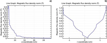
As can be seen in Figure 2, a column of neutral gas above the anode is strongly ionized as a result of discharge current and the electrons movement to the top of the anode. Therefore, the cloud of electrons, which exceeds the number of generated ions from gas ionization, moves towards the anode. Due to the electrostatic force between the ions and the electron cloud and the anode positive potential cover generated by the electron cloud, ions are moved to the anode after electrons. In our simulation the electron cloud is a column of electrons with a height of about 1 cm. At this moment, the flow of electrons in this column reaches more than 200 kA. The axial and radial variations of the magnetic field strength to the central axis on the top of the anode are illustrated in Figure 3.
(a) The axial and (b) radial variations of the magnetic field strength to the central axis on the top of the anode.

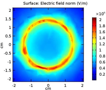
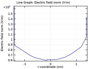
By moving the electron cloud downward (to the top of the anode), ions will follow it due to the electrostatic attraction force. It should be noted that the number of electrons in the electron cloud is far more than the number of ions. Moving the electron cloud towards the anode, the effect of anode potential on ions is neutralized until the moment of collision. Due to collision of the electron cloud with the top of the anode and the positive potential of the anode, acceleration of ions begins. Three main phenomena influence the ions acceleration. These phenomena are drift motion due to the electrical field and drift motion due to the magnetic field gradient. The strength of the electric field on the top of the anode and its variation over the anode diameter is illustrated in Figures 4 and 5, respectively.
The strength of the electric field on the top of the anode.

Variation of electric field on the top of the anode and over its diameter.

As can be seen in Figure 3a, the magnetic field (B) and its gradient are in the φand z-directions, respectively, in cylindrical coordinates. The result leads to the drift motion due to the field gradient (
 $V_{\nabla {\rm B}} $
) as:
 $$v_{\nabla {\rm B}} = \mp \displaystyle{{v^2} \over {2{\rm \omega} _{\rm c}}} \displaystyle{{B \times \nabla B} \over {B^2}} = \mp \displaystyle{{v^2} \over {2{\rm \omega} _{\rm c}}} \displaystyle{{\nabla B} \over B}{\hat {\bf r}}\; $$
Where ωc and v are the Larmor frequency and the original velocity, respectively.
In other words, the magnetic field gradient in the z-axis of the PFD results from the electron cloud movement and compression in radial direction. Moreover, this gradient of the magnetic field in the z-direction is a consequence of the radial movement of ions and their divergence.
As can be seen from Figure 3b, the gradient of the magnetic field is also observed in the radial axis. Therefore, the motion drift of ions and electrons in the radial axis results from the other motion drift (
 ${\mathop v\limits^{{\prime} }} _{\nabla {\rm B}} $
) in the z-direction:
 $${\mathop v\limits^{{\prime} }} _{\nabla {\rm B}} = \mp \displaystyle{{v^2} \over {2{\rm \omega} _{\rm c}}} \displaystyle{{\nabla B} \over B}{\hat {\bf z}}$$
Using spherical coordinates, these two equations can be summarized as follows:
 $$v_{\nabla {\rm B}} = \mp \displaystyle{{v^2} \over {2{\rm \omega} _{\rm c}}} \displaystyle{{\nabla B} \over B}{\hat {\bf \theta}} $$
The radial field and its gradient are in the same order so:
 $$\displaystyle{{\nabla B} \over B} \approx 1 \to v_{\nabla {\rm B}} = \mp \displaystyle{{v^2} \over {2{\rm \omega} _{\rm c}}}, \quad \; v \approx v_{\rm T} $$
The drift motion due to the
 ${\bf E} \times {\bf B}$
and as discussed above, the coulomb repulsion force are the main factors leading to the acceleration of ions. As shown in Figures 4 and 5, the electric field will increase by approaching the anode top and reaches its maximum value, that is, 2.1 × 10⁶ V/m.
The
 ${\bf E} \times {\bf B}$
drift motion (v
E) has two components along the r and θ-directions:
 $$v_{\rm E} = \displaystyle{{( - E_{\rm r} {\hat {\bf r}} + E_{\rm \theta} {\hat {\bf \theta}} ) \times B_{\rm \varphi} {\hat {\bf \varphi}}} \over {B^2}} = \displaystyle{{E_{\rm r} {\hat {\bf \theta}} + E_{\rm \theta} {\hat {\bf r}}} \over B}$$
According to this equation, the drift motion is independent of particle mass. It may be thought that the heavy particles will gain more energy than the lighter particles due to the drift motion. The kinetic energy obtained by the ions with electrostatic force due to the movement of ions following the electrons is proportional to the inverse of the ion mass. Therefore, the light ions are faced with a stronger electric field, magnetic field, and magnetic field gradient than heavy ions. As a result, the drift motion of light ions is more than heavy ones.
4. CONCLUSION
In this paper, the reasons for the acceleration and distribution of ions and electrons in the PFDs are investigated using the COMSOL Multiphysics version 5. Finally, the following results are achieved:
-
1. Due to electrostatic forces between the ions and the electron cloud as well as the positive potential cover caused by the electron cloud, ions follow the electrons towards the top of the anode.
-
2. Contrary to various reported works, because of the drift motion due to the gradient of the magnetic field and
 ${\bf E} \times {\bf B}$
drift motion, the ions on the top of the anode move in the θ-direction in spherical coordinates.
-
3. With the collision of the electron cloud and the anode, ions will be faced with the positive potential in the top of the anode and the coulomb repulsion force in addition to the
${\bf E} \times {\bf B}$
drift motion also contributing to the acceleration of ions. -
4. The magnetic field gradient in the z-axis on the top of the anode results in radial movement and the electron column compression.
-
5. The magnetic field gradient in the radial direction on the top of the anode results in the movement of the electrons and ions in the z-axis in the opposite direction.
-
6. The most energetic ions dealt with the upper wall of the PFD near-zero angles with respect to the axis of the device and its energy reduced with distance from the zero degree.
-
7. The different results of some experiments indicate high energetic ion beams collide with tip of anode. there is no possibility for all the presented mechanisms until now to justify this ion beams collision. The presented mechanism in this manuscript, has ability to justify ion beams collision with tip of anode.