1. Introduction
Demand for economical, safe, and reliable access-to-space systems will continue to grow as the global economy becomes ever more reliant on space-based systems for activities such as communication, remote sensing and climate monitoring to name a few. Extending air-breathing technology to hypersonic vehicles through the use of an air-breathing supersonic combustion ramjet, or scramjet, engine has great potential for achieving such requirements. This is due to the potential improved performance in terms of fuel-weight-flow-rate specific thrust, or specific impulse (
 $I_{sp}$
), that air-breathing scramjets offer over traditional rocket launch systems together with their potential reusability (Smart & Tetlow Reference Smart and Tetlow2009). Combining scramjets with more traditional launch vehicles, therefore, offers a more fuel and weight efficient launch system. Achieving this hybrid launch vehicle will require the scramjet engine component to operate in the approximate Mach number (
 $M$
) range 8–12 at altitudes between 30 and 40 km. At these speeds and altitudes, not only is the air captured less dense but flow through the combustor remains hypersonic, travelling at speeds between 2400 and
 $3600~\text{m}~\text{s}^{-1}$
. This raises many technical challenges on how to initiate and sustain combustion to a level that provides net thrust at these conditions. Porous fuel injection and oxygen enrichment (Rudakov & Krjutchenko Reference Rudakov and Krjutchenko1990; Heiser & Pratt Reference Heiser and Pratt1994; Portwood Reference Portwood2006; Razzaqi & Smart Reference Razzaqi and Smart2011) used within a radical farming scramjet (RFS) (Odam & Paull Reference Odam, Paull, Tropea, Jakirlic, Heinemann, Henke and Hönlinger2007; McGuire, Boyce & Mudford Reference McGuire, Boyce and Mudford2008) are two independent technologies that have been identified as possible methods of enhancing and promoting supersonic combustion at the high Mach numbers and altitudes required for air-breathing access-to-space trajectories.
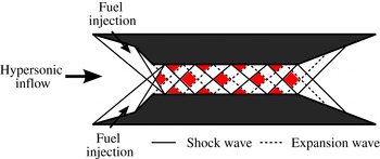
Inlet fuelled RFS are a scramjet class extensively studied within the Australian Hypersonic community (Odam & Paull Reference Odam, Paull, Tropea, Jakirlic, Heinemann, Henke and Hönlinger2007; McGuire et al. Reference McGuire, Boyce and Mudford2008; Boyce et al. Reference Boyce, Schloegel, McIntyre and Tirtey2011; Brieschenk et al. Reference Brieschenk, Capra, Lorrain, McIntyre and Boyce2012; Lorrain et al. Reference Lorrain, Brieschecnk, Capra and Boyce2012; Schloegel et al. Reference Schloegel, Boyce, McIntyre and Tirtey2012). These engines offer a number of advantages over other classes of scramjets including: milder compression ratios; enhanced fuel/mainstream air mixing at combustor entry (Gardner, Paull & McIntyre Reference Gardner, Paull and McIntyre2002); reduced combustion chamber lengths (and hence skin friction drag) (McGuire et al. Reference McGuire, Boyce and Mudford2008); and reduced fuel ignition times (Paull & Stalker Reference Paull and Stalker1998). The operating principle of an inlet fuelled RFS is shown in figure 1. The intake shock structure is designed such that the leading edge and intake ramp shocks interact and reflect in a way that generates a shock wave–expansion fan structure that is purposefully ingested into the combustion chamber. Through shock–shock interactions and reflections, this wave structure creates localised regions of high pressure and temperature, known as ‘hot pockets’ (HP) within the combustion chamber, as identified by the shaded regions in figure 1, while maintaining an overall mild compression process. It is within these regions that the characteristic ignition–combustion process of RFS occurs, namely: radical (OH, O and H) production; radical build-up; and, ultimately, fuel ignition (McGuire et al. Reference McGuire, Boyce and Mudford2008).
Schematic of the radical farming process (adapted from Odam Reference Odam2004).

A key requirement of these engines is that the fuel and air is adequately mixed at the entrance to the combustion chamber, and particularly within the hot pocket regions. Typically, this is achieved with sonic fuel injection via a series of small portholes located on the first or second intake ramp. This fuel delivery method within RFS has consistently been shown to result in appreciable combustion within these engines at test Mach numbers in the range of 5–6.5 with no noticeable combustion-induced pressure rise due to fuel burning on the inlet (Gardner et al. Reference Gardner, Paull and McIntyre2002; Kovachevich, Paull & McIntyre Reference Kovachevich, Paull and McIntyre2004). A pilot, and unpublished, study performed by researchers at the University of Queensland in 2010 investigated the use of a novel alternative fuel injection system that utilised a purpose-built porous injector. Using a flat, tapered rectangular carbon–carbon (C/C) injector, the pilot study indicated that this fuel injection method resulted in two key improvements over the more traditional porthole injection: a more favourable injection shock structure and higher overall combustion pressure rise.
A recent numerical study by Capra et al. (Reference Capra, Boyce, Kuhn and Hald2015) further demonstrated that for porous fuel injection with hydrogen and a C/C injector, the injection shock remained attached and, consequently, no separated flow regions were found to be present on the inlet in the region of fuel injection when porous fuel injection was employed. This is in direct contrast to porthole injection which is characterised by separated regions both up- and downstream of injection (Ben-Yaker, Mungal & Hanson Reference Ben-Yaker, Mungal and Hanson2006; Viti, Neel & Schetz Reference Viti, Neel and Schetz2009). Capra et al.’s study also showed that for the same inflow conditions and fuelling level, porous fuel injection resulted in the propagation of a stronger shock wave–expansion fan structure through the engine and enhanced fuel–air mixing. The combined effect of these was an overall greater mixing and combustion efficiency and demonstration that combustion chamber length could be reduced with porous fuel injection by 25 %.
Oxygen enrichment, whereby small levels of
 $\text{O}_{2}$
are pre-mixed with fuel prior to injection into a scramjet engine, is one method proposed to extend the flight corridor of scramjets into the access-to-space range (Rudakov & Krjutchenko Reference Rudakov and Krjutchenko1990; Heiser & Pratt Reference Heiser and Pratt1994). This augmentation of fuel with
 $\text{O}_{2}$
thus allows the possibility for combustion to be enhanced/promoted at flight conditions and altitudes where freestream oxygen levels are insufficient to allow timely mixing and combustion of fuel. Limited studies, both numerical (Rudakov & Krjutchenko Reference Rudakov and Krjutchenko1990; Petty et al.
Reference Petty, Wheatley, Smart and Razzaqi2013) and experimental (Portwood Reference Portwood2006; Razzaqi & Smart Reference Razzaqi and Smart2011) on the performance of
 $\text{O}_{2}$
enriched scramjets have been performed on and off since the 1990s. Rudakov & Krjutchenko (Reference Rudakov and Krjutchenko1990) were the first to explore such benefits using a one-dimensional computational study employing equilibrium chemistry allowing for dissociation. Results from their study demonstrated that, through the addition of
 $\text{O}_{2}$
to a theoretical hydrogen fuelled diverging combustor scramjet operating at a dynamic pressure (
 $q=0.5{\it\rho}V^{2}$
, where
 ${\it\rho}$
is the freestream density and
 $V$
is the freestream velocity) of 75 kPa, significant increases in both the specific impulse and the overall density impulse, particularly in the Mach 8–16 range, could be achieved. Density impulse is analogous to specific impulse but with fuel density considered instead of mass, and thus quantifies the impulse achieved per unit volume of fuel/propellant. The benefit of a higher density impulse manifests itself in tankage requirements, specifically that smaller tanks can be used to deliver the same density impulse (Rudakov & Krjutchenko Reference Rudakov and Krjutchenko1990). Interest in oxygen-enriched scramjet operation then appeared to stagnate until 2006, when Portwood (Reference Portwood2006) performed an experimental study of an
 $\text{O}_{2}$
enriched ethylene (
 $\text{C}_{2}\text{H}_{4}$
) fuelled nominally two-dimensional (2D) scramjet (similar to the one examined in this study) employing both inlet porthole fuel injection and radical farming concepts. The engine was tested in the T4 Shock Tunnel at The University of Queensland using the Mach 6 contour nozzle at total enthalpies (
 $h_{0}$
) and dynamic pressures of
 $3{-}7~\text{MJ}~\text{kg}^{-1}$
and 240–285 kPa respectively.
At total enthalpies in the range
 $4{-}7~\text{MJ}~\text{kg}^{-1}$
, Portwood reports a reduction in ignition and combustion length with
 $\text{O}_{2}$
enrichment but measured no notable increase in thrust or incremental specific impulse. Further, at oxygen-enriched low equivalence ratios (
 ${\it\Phi}<0.2$
), the engine was consistently found to choke, a phenomenon attributed to the immediate combustion of the
 $\text{O}_{2}{-}\text{C}_{2}\text{H}_{4}$
mixture upon injection. This conclusion, however, was based solely on pressure measurements as no optical, or surface heat transfer measurements were taken during the experimental campaign. More recently, experimental (Razzaqi & Smart Reference Razzaqi and Smart2011) and numerical (Petty et al.
Reference Petty, Wheatley, Smart and Razzaqi2013) studies of an
 $\text{H}_{2}$
fuelled strut injection hypervelocity combustor provided further evidence that
 $\text{O}_{2}$
enrichment can offer realisable benefits to scramjet engines. Razzaqi & Smart (Reference Razzaqi and Smart2011) experimentally showed that ignition length can be reduced with
 $\text{O}_{2}$
enrichment. For example, they report that an enrichment percentage of 6.4 % resulted in a 70 mm or a 7.8 % reduction in the onset of a noticeable pressure rise, and hence inferred ignition, compared to an equivalent non-enriched case. When the level of enrichment was increased to 13.9 % the point of ignition was reported to reduce by 150 mm or 16.7 %.
The engine used in these studies was reported to be mixing limited (Razzaqi & Smart Reference Razzaqi and Smart2011), and as such, an improvement in local equivalence ratio is the physical mechanism driving the reduction in ignition length with oxygen enrichment. This improvement is a result of the head start that the pre-mixing of oxygen with fuel prior to injection into the engine has on the overall fuel–air mixing achieved with no oxygen enrichment. Importantly, these studies found that
 $\text{O}_{2}$
enrichment does increase the combustion efficiency, with evidence that it caused more fuel to be burned compared to unenriched cases, an observation attributed to the secondary effects of
 $\text{O}_{2}$
enrichment such as enhanced mixing (Petty et al.
Reference Petty, Wheatley, Smart and Razzaqi2013), and in direct contrast to the previous study of Portwood (Reference Portwood2006). The long term realisable benefit of
 $\text{O}_{2}$
enrichment has the potential to reduce combustion chamber lengths while maintaining overall combustion levels, thereby increasing scramjet efficiency through the reduction of skin friction drag associated with long combustors.
RFS, porous fuel injection and oxygen enrichment have all demonstrated independently that they have the ability to extend and enhance scramjet performance. With this in mind, an experimental study was conducted with the aim of quantifying the combustion enhancement, if any, associated with
 $\text{O}_{2}$
-enriched porous fuel injection in a RFS operating at Mach 9 flight conditions at an equivalent flight altitude of
 ${\approx}31.3~\text{km}$
and dynamic pressure of 56.3 kPa. This flight condition was chosen as it is representative of the entry Mach number range for air-breathing access-to-space trajectories. All experiments were performed in the T4 Shock Tunnel in a nominally 2D engine with hydrogen fuel and two levels of
 $\text{O}_{2}$
enrichment. Parameters used to specify the level of
 $\text{O}_{2}$
enrichment are first presented before a detailed description of the test model, injectors, facility and test condition is given. Results of the experimental campaign are then presented with discussion emphasising the influence that
 $\text{O}_{2}$
enrichment has on combustion-induced pressure rise and engine performance.
2. Fuelling and enrichment parameters
The equivalence ratio (
 ${\it\Phi}$
) is the primary parameter detailing the amount of fuel supplied to an engine. For this study, it is defined as the ratio of actual fuel mass to oxidiser mass (
 $g_{actual}$
) captured by the intake divided by the stoichiometric ratio of fuel mass to oxidiser mass (
 $g_{stoich}$
):
 $$\begin{eqnarray}{\it\Phi}=\frac{g_{actual}}{g_{stoich}}=\frac{\left({\dot{m}}_{fuel}/{\dot{m}}_{\text{O}_{2}}\right)_{actual}}{\left({\dot{m}}_{fuel}/{\dot{m}}_{\text{O}_{2}}\right)_{stoich}}.\end{eqnarray}$$
Stoichiometiric combustion in a hydrogen fuelled scramjet requires one mole of oxygen (
 $32~\text{g}~\text{mol}^{-1}$
) to fully consume two moles of hydrogen (
 $2~\text{g}~\text{mol}^{-1}$
). Therefore, the mass flow rate of oxygen must be eight times greater than hydrogen for stoichiometiric combustion, or
 $g_{stoich}=1/8$
. Substituting this into (2.1) gives a reduced expression for
 ${\it\Phi}$
:
 $$\begin{eqnarray}{\it\Phi}=8g_{actual}=8\cdot \frac{{\dot{m}}_{\text{H}_{2}}}{{\dot{m}}_{\text{O}_{2}}}.\end{eqnarray}$$
It is important to note that the mass flow rate of
 $\text{O}_{2}$
in this equation represents oxidiser captured by the intake and does not include additional
 $\text{O}_{2}$
supplied through enrichment.
Quantifying the level of
 $\text{O}_{2}$
enrichment and the impact this has on the equivalence ratio is necessary to understand the effect enrichment has on the ignition and combustion process in scramjet engines. Portwood (Reference Portwood2006) defines a number of parameters to describe the level of enrichment, the most useful being the enrichment percentage, EP, which is defined as the mass flow rate of additional
 $\text{O}_{2}$
expressed as a percentage of the mainstream
 $\text{O}_{2}$
. This definition, however, provides no insight into the magnitude of the
 $\text{O}_{2}$
enrichment with respect to how fuel-rich or fuel-lean the combustion will be. In this study, therefore, EP is defined as the mass flow rate of additional
 $\text{O}_{2}$
expressed as a percentage of only that part of the mainstream
 $\text{O}_{2}$
that would be consumed if fully reacted with the available fuel. That is,
 $$\begin{eqnarray}\mathit{EP}=100\frac{{\dot{m}}_{\text{O}_{2,add}}}{{\it\Phi}{\dot{m}}_{\text{O}_{2}}}=100\frac{{\dot{m}}_{\text{O}_{2,add}}}{8{\dot{m}}_{fuel}},\end{eqnarray}$$
where
 ${\dot{m}}_{\text{O}_{2,add}}$
indicates the mass of
 $\text{O}_{2}$
added to the fuel through enrichment prior to injection. The last parameter used to describe the fuelling and enrichment of the scramjet is the enriched equivalence ratio,
 ${\it\Phi}_{en}$
:
 $$\begin{eqnarray}{\it\Phi}_{en}=8\frac{{\dot{m}}_{\text{H}_{2}}}{{\dot{m}}_{\text{O}_{2}}+{\dot{m}}_{\text{O}_{2,add}}}.\end{eqnarray}$$
This parameter is similar to (2.2), however it includes the mass flow rate of the additional oxidiser introduced during the enrichment process and therefore includes all oxidiser available within the engine. For enriched cases,
 ${\it\Phi}_{en}$
is always smaller than
 ${\it\Phi}$
due to the inclusion of the additional mass flow rate of oxygen, whereas for unenriched cases
 ${\it\Phi}_{en}={\it\Phi}$
.
3. Experimental set-up and flow conditions
3.1. Experimental model and fuelling system
A previously tested (Boyce et al.
Reference Boyce, Schloegel, McIntyre and Tirtey2011; Schloegel et al.
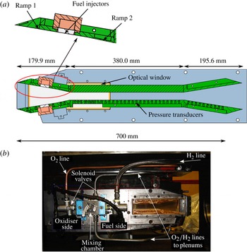
Reference Schloegel, Boyce, McIntyre and Tirtey2012) nominally 2D inlet fuelled RFS was modified and re-instrumented for the experimental testing reported in this paper. Modifications made included increasing the combustion chamber height by 6 mm to ensure shock reflection at the operating condition occurred within the combustion chamber and not on the intake, and replacement of the porthole injectors with oxygen compatible porous injectors for mainstream fuel delivery. A schematic and photograph of the mounted test model is shown in figure 2(a,b). All other aspects of the physical geometry of the engine were maintained. The assembled test engine measured 755.5 mm long and consisted of: two inlet ramps having a combined horizontal length of 179.9 mm (134.9 mm first ramp, 45 mm second ramp) and turning angle of 12° (9° and 3° respectively); a 380.0 mm long and 26.0 mm high combustion chamber; and a 195.6 mm long (horizontal) thrust nozzle with a 9° half-angle. The engine intake was 87.6 mm high with a spanwise width of 75 mm, giving a capture area of
 $6.57\times 10^{-3}~\text{m}^{2}$
and contraction ratio of 3.37. All leading edges were sharp at the commencement of the test campaign. The model was constructed from stainless steel except for the bottom combustion chamber plate which was made from aluminium. Both thrust nozzles and the top combustion chamber surface had a plate thickness of 12 mm except near the edges which had a thickness of 24 mm for mounting purposes. The duel ramp inlets were 8 mm thick, with recesses for enhanced instrumentation installation. A 24 mm thick aluminium plate, with recesses for instrumentation was used for the bottom combustion chamber surface for weight and cost requirements. This plate also housed a series of aluminium and Acetyl inserts near the inlet to allow for a number of heat transfer and pressure gauge configurations. These inserts had the same thickness as the remainder of the plate that had been milled for instrumentation (13 mm). No surface finish was specified in the original model drawings.
(a) Schematic (adapted from Lorrain, Brieschecnk & Boyce Reference Lorrain, Brieschecnk and Boyce2013) and (b) photograph of the model mounted in the T4 shock tunnel (no shielding).

Fuel (
 $\text{H}_{2}$
) and oxidiser (
 $\text{O}_{2}/\text{N}_{2}$
) were supplied to the engine via two independent Ludwieg tubes located external to the test section. For safety reasons, pure
 $\text{O}_{2}$
was not used, instead a mix of
 $75\,\%~\text{O}_{2}/25\,\%~\text{N}_{2}$
was used to enrich the fuel. Addition of nitrogen into the oxidiser flow sufficiently reduced the upper explosion limit of the pre-mixed
 $\text{H}_{2}{-}\text{O}_{2}{-}\text{N}_{2}$
mixture such that all enrichment levels examined remained too fuel rich to sustain a flame if accidental ignition were to occur upon mixing (Schroeder & Holtappels Reference Schroeder and Holtappels2005). Nitrogen in the oxidiser stream has no influence on the EP or
 ${\it\Phi}_{en}$
values reported in this paper, as both of these parameters depend only on
 $\text{H}_{2}$
and
 $\text{O}_{2}$
(see § 2). It does, however, affect the blowing rate of the injectors, and therefore has an impact on the injection flow structures, increasing the density and pressure in the flow field. This effect has been accounted for through pressure measurements of enriched fuel experiments with an
 $\text{N}_{2}$
test gas.
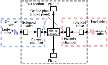
Two ASCO/JOUOMATIC fast acting solenoid valves (response times 15–60 ms) were used to deliver the fuel and oxidiser to the model during a test. Figure 3 shows a schematic of the fuel and oxidiser systems. Both solenoid valves were triggered from the tunnel recoil, which was repeatable at
 $142.8\pm 0.6~\text{mm}$
, and opened for 120 ms. The long valve opening time was necessary to ensure a steady plenum pressure to each fuel injector was achieved during the test time. Hydrogen pressure was found to be consistently very steady during this time; however, the oxidiser flow rate changed slightly throughout the test time (
 ${<}2\,\%$
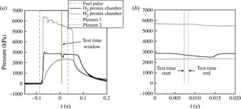
), and was assumed constant. Figure 4 illustrates typical fuel, oxidiser and plenum pressure profile throughout the valve opening time (a) and during the test time (b). For the experiment shown, fuel (
 $\text{H}_{2}$
) supply pressure was invariant over the test time, plenum pressures changed by less than 1 % and the oxidiser flow reduced by less than 1.5 %. This result was typical of all enriched experiments performed.
Schematic of oxidiser and fuel delivery to test model.

Sample fuel, oxidisers and plenum pressure traces during (a) valve opening and (b) test time for enriched experiments.

Upon valve opening, each flow stream entered a pre-mix chamber each with volume
 $1.362\times 10^{-5}~\text{m}^{3}$
, before passing through an orifice plate into the mixing chamber (volume of
 $6.809\times 10^{-5}~\text{m}^{3}$
) where the fuel and oxidiser streams were mixed (figure 3). For these experiments, two different orifice plates were used on the oxidiser (
 $1\times \varnothing 1.7~\text{mm}$
) and fuel (
 $4\times \varnothing 1~\text{mm}$
) sides, respectively. These plates were chosen to ensure that each flow choked when each side was tested independently. For example, the fuel side orifice plate was selected as this produced a choked fuel stream into the fuel pre-mix chamber when a blank orifice plate (no orifice) was installed on the oxidiser side to prevent flow. Likewise, an orifice plate with one hole at 1.7 mm diameter was found to produce choked oxidiser flow when no fuel was present. An additional requirement of the selection of the fuel side orifice plate was that the fuel remained choked during enriched experiments, as shown in figure 4. This was found to be achieved with the selected fuel side orifice plate with
 $4\times 1~\text{mm}$
diameter holes. During fuel calibration it was found that it was not possible to achieve both a choked fuel and oxidiser flow during the enriched experiments. This is demonstrated in the sample fuel, oxidiser and plenum pressures shown in figure 4 which clearly shows that the fuel stream has choked but the oxidiser has not. This behaviour was reported by both Portwood (Reference Portwood2006) and Razzaqi & Smart (Reference Razzaqi and Smart2011) and is a feature of the experimental system, namely the relatively large mixing chamber volume and the small test times. Because of this, only the fuel side was choked during the enriched experiments.
The now mixed
 $\text{H}_{2}/\text{O}_{2}/\text{N}_{2}$
fluid was then supplied to the two engine plenums (volume of
 $1.989\times 10^{-5}~\text{m}^{3}$
) via
 $1/2~\text{in.}$
tubes. Unlike previous use of the oxygen enrichment system in T4, the mixed gas was not choked again. This was possible as flow into the porous fuel injectors does not need to be choked to quantify the mass flow rate, and actually remains un-choked. Using the method detailed below, the mass flow rate of
 $\text{O}_{2}/\text{N}_{2}$
could be determined based on the known fuel mass flow rate and measured plenum pressures without the need to choke either the oxidiser stream or the
 $\text{H}_{2}/\text{O}_{2}/\text{N}_{2}$
mixture.
3.2. Porous fuel injectors and fuelling levels
Mainstream fuel injection was performed on the first intake ramp (top and bottom) 95 mm downstream of the leading edge through the porous injectors. They were made of a ceramic matrix composite (CMC) material where oxide Nextel™ 610 fibres are embedded in a alumina–zirconia based oxide matrix. In contrast to previously applied C/C composites (Capra et al. Reference Capra, Boyce, Kuhn and Hald2015), this material can be penetrated with oxygen-enriched fuels in high temperature environments. This environment corresponds to operationally relevant conditions of scramjet engines, rather than tunnel conditions, and hence increases the technological readiness of such porous injection systems for flight applications.
The fuel injectors were 44.4 mm wide and 28 mm long on the flow path side, and had a thickness of 6 mm and a 20° taper on each side so that the plenum facing side was 10.1 % larger in area than the flow path side. As the composite material exhibits an orthotropic structure, fuel penetrates the sample in-plane along the fabric layers while the others were arranged in line with the inlet flow. Average raw density (
 ${\it\rho}$
) and open porosity of the injectors was
 $2832.1\pm 10.6~\text{kg}~\text{m}^{-3}$
and
 $28.6\pm 0.2\,\%$
, respectively.
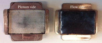
Limited soot deposits, as shown in figure 5, were found to develop on the injectors during all experiments, increasing to significant levels for the fuel-off shots. Fuel timing ensured that a supply of fuel, and hence blowing gas, was present prior to, and well after, the arrival of the test gas. Soot deposition therefore occurs post test time, when the fuel blowing ceases and outside the test time. To minimise excessive degradation of the pore size and structure of the injectors, fuel-off shots were performed last.
 $\text{O}_{2}$
compatible porous injectors post testing.

Fluid flow through porous media is characterised by a pressure drop sustained over the thickness of the media (
 ${\rm\Delta}p/L$
) and is influenced by a number of parameters including, but not limited to: material, structure morphology, number of layers and layer disposition (Gascoin et al.
Reference Gascoin, Fau, Kuhn, Bouchez and Steelant2012). For low velocity (
 $U$
) flow this viscous pressure drop is characterised by Darcy’s law which gives a linear correlation between pressure drop and average superficial velocity,
 $V$
(Nield & Bejan Reference Nield and Bejan2006). As flow velocities increase, this linearity is inadequate to calculate the pressure drop and a second, inertia-related term is added which is often referred to as Forchheimer flow (Nield & Bejan Reference Nield and Bejan2006). Complete characterisation of porous media operating within a low and high velocity range must, therefore, incorporate both the Darcy and Forchheimer flow regimes. The resulting pressure drop when both regimes are considered is
 $$\begin{eqnarray}\displaystyle \frac{{\rm\Delta}p}{L}=\frac{p_{in}^{2}-p_{out}^{2}}{2p_{in}L}=\frac{{\it\mu}_{in}}{k_{D}}V_{in}+\frac{{\it\rho}_{in}}{k_{F}}V_{in}^{2},\end{eqnarray}$$
the so-called Darcy–Forchheimer equation (Hald et al.
Reference Hald, Herbertz, Ortelt and Kuhn2009; Langener, von Wolfersdorf & Steelant Reference Langener, von Wolfersdorf and Steelant2011; Gascoin et al.
Reference Gascoin, Fau, Kuhn, Bouchez and Steelant2012). Using the perfect gas relation along with continuity, this equation can be expressed as a quadratic in mass flow rate,
 ${\dot{m}}$
:
 $$\begin{eqnarray}\displaystyle \frac{{\it\rho}_{in}}{k_{F}{\it\rho}_{in}^{2}A^{2}}{\dot{m}}^{2}+\frac{{\it\mu}_{in}}{k_{D}{\it\rho}_{in}A}{\dot{m}}-\frac{p_{in}^{2}-p_{out}^{2}}{2p_{in}L}=0,\end{eqnarray}$$
thereby allowing for injected mass flow rate to be computed for a know gas composition, plenum pressure and injector exit area (
 $A$
).
In (3.1) and (3.2) the
 $in$
properties refer to those in the fuel plenums while the
 $out$
terms refer to the injection environment (post leading edge shock) and the terms
 $k_{D}$
and
 $k_{F}$
are the Darcy and Forchheimer coefficients respectively. These coefficients are material dependent values that need to be evaluated experimentally for each batch of material. Provided the porous injectors sustain no cracks or fissures during experimentation, these coefficients can be considered constant (Gascoin et al.
Reference Gascoin, Fau, Kuhn, Bouchez and Steelant2012). Injectors used in these experiments were orthotropic; however, for fuel/oxidiser characterisation only the parallel (in-plane along the ceramic fabric layers of the injector) coefficients are required in (3.1) and (3.2) to consider the enriched fuel flow in the porous injector and in the streamwise flow direction. Latitudinal fuel flow distribution within the porous injector has been neglected. Experimental determination indicated the injectors had the following in-plane permeabilities prior to experimental testing:
 $k_{D}=1.2824\times 10^{-13}~\text{m}^{2}\pm 1.8\,\%$
and
 $k_{F}=5.1209\times 10^{-8}~\text{m}\pm 4.7\,\%$
. Equation (3.2) is seen to be dependent only on the inflow properties rather than the mean flow properties within the sample, although mean values have been assumed here (theoretical derivation described in Gascoin et al.
Reference Gascoin, Fau, Kuhn, Bouchez and Steelant2012). This feature of (3.2) lends itself to numerical, analytical and experimental studies where only inflow conditions are known (such as the current study) and is commonly used at both DLR and ESA (Gascoin et al.
Reference Gascoin, Fau, Kuhn, Bouchez and Steelant2012) along with other researchers (Langener et al.
Reference Langener, von Wolfersdorf and Steelant2011).
For each case (fuel only and enriched), the mass flow rate of hydrogen was computed from a choked flow analysis using hydrogen Ludwig tube and hydrogen pre-mix chamber pressure measurements. The amount of fuel supplied to the engine for each case was thus determined to be
 $8.89\times 10^{-3}\pm 1.3\,\%~\text{kg}~\text{s}^{-1}$
. Temperature of the gas in the fuel plenums (and hence inflow viscosity,
 ${\it\mu}$
, and density) was then determined for the fuel-only cases using the recorded plenum pressure, known mass flow rate of hydrogen and (3.2). From this method, the temperature of the fuel just prior to entering the porous injector was computed to be 152 K. This was then held constant for the enriched cases. Mass flow rates of the added oxidiser mix for the enriched cases was then computed through iteratively solving (3.2) for a known plenum pressure and mass flow rate of hydrogen. Table 1 summarises the resulting oxidiser mass flow rates and enrichment parameters calculated through iteration of (3.2). Uncertainties in the mass flow rate values and fuelling parameters have been calculated from a sensitivity analysis on the uncertainties in the plenum pressure measurements, freestream values and injector permeabilities.
Fuelling and enrichment parameters.

3.3. Instrumentation and optics
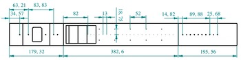
The test model was instrumented with a total of 47 fast response Kulite pressure transducers within the main flow of the engine. Pressure transducers were distributed as follows: five on the intake centreline, 27 on the combustion chamber centreline and 10 off-centre, and five on the thrust nozzle centreline. These locations are shown in figure 6. An additional five PCB® pressure transducers were installed within the fuel system, including one in each plenum and three within the mixing chamber assembly (mixing chamber and two pre-mix chambers).
Location of pressure transducers within the engine flow path. All dimensions in mm.

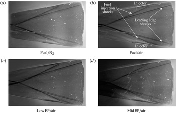
Schlieren imaging of the intake shock structures was performed on a number of experiments to determine the starting behaviour of the engine and the fuel injection shock characteristics. BK7 optical glass was used for all schlieren imaging.
3.4. Test facility and freestream conditions
All experiments were performed in the T4 free-piston-driven hypersonic shock tunnel at The University of Queensland (Stalker Reference Stalker1967). An impulse facility operating in the reflected shock tube mode, T4 is capable of simulating flows up to Mach 10 and nozzle supply enthalpies of up to
 $9~\text{MJ}~\text{kg}^{-1}$
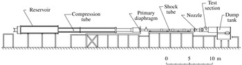
with useful test times for experimental testing (Boyce, Takahashi & Stalker Reference Boyce, Takahashi and Stalker2005). The facility, schematically shown in figure 7, consists of five main sections: reservoir, compression tube, shock tube, nozzle, and a combined test section and dump tank. Mild steel diaphragms of varying thicknesses (6 mm was used in this study) separate the compression tube from the shock tube while a light, mylar diaphragm, separates the shock tube and nozzle throat when the tunnel is in its firing position. Tunnel operation begins when high pressure from the reservoir is released into the piston cavity causing the 95 kg free piston to accelerate along the compression tube adiabatically compressing the driver gas. The primary diaphragm ruptures when the compressed driver gas reaches the burst pressure, forming a shock wave which propagates into the shock tube. This shock wave then compresses, heats, and accelerates the test gas (air or nitrogen) behind it until it reaches the secondary diaphragm at the nozzle throat where it is then reflected. This reflected shock travels in the reverse direction, further compressing and stagnating the test flow, thus providing the reservoir conditions for the nozzle expansion. Upon rupture of the secondary diaphragm, the mostly stagnant test gas is expanded through a nozzle into the test section and dump tank.
Schematic of T4 shock tunnel (Tanimizu Reference Tanimizu2008).

Through the adjustment of the driver operating conditions, primary diaphragm thickness and shock tube initial pressure, the T4 facility can be operated at nozzle reservoir pressures and stagnation enthalpies in the range of 10–80 MPa and
 $2{-}9~\text{MJ}~\text{kg}^{-1}$
respectively. Four contoured nozzles designed to produce Mach 4, 6, 7.6 and 10 freestream flows within the test chamber are currently available for use in T4. For the current experiments, the contoured M7.6 nozzle was used. This nozzle has a throat and exit diameter of 16.39 mm and 270 mm respectively and a total length of 1170 mm. The current experiments were conducted at a nozzle reservoir pressure and enthalpy of approximately 39 MPa (air)–39.9 MPa (
 $\text{N}_{2}$
) and
 $3.93~\text{MJ}~\text{kg}^{-1}$
(air)–
 $4.25~\text{MJ}~\text{kg}^{-1}$
(
 $\text{N}_{2}$
) respectively, for which useful test time, with less than 10 % driver gas contamination (Boyce et al.
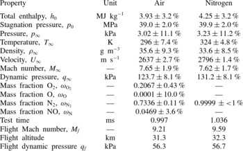
Reference Boyce, Takahashi and Stalker2005), was between 0.63 and 1.5 ms. Average freestream properties delivered by this nozzle for the results presented in this paper are given in table 2. These values represent the average of the freestream properties of all experiments and have been calculated using experimentally measured shock speed and nozzle reservoir stagnation pressure in combination with the numerical tool NENZF (Lordi, Mates & Moselle Reference Lordi, Mates and Moselle1966). This tool is a quasi-one-dimensional numerical analysis that computes inviscid expansion for finite rate chemistry.
Average freestream conditions.

Equivalent flight Mach number, dynamic pressure and altitude are also shown in table 2. The flight Mach number was computed based on the total enthalpy from the nozzle exit
 $$\begin{eqnarray}h_{0}=C_{P}T_{flight}+{\textstyle \frac{1}{2}}{\it\gamma}RT_{flight}M_{flight}^{2},\end{eqnarray}$$
with standard values for the specific heat at constant pressure (
 $C_{p}$
), ratio of specific heats (
 ${\it\gamma}$
) and gas constant (
 $R$
).
The flight freestream temperature (
 $T_{flight}$
) was correlated to the tunnel freestream static pressure through equivalent altitude using the US Standard Atmosphere (USSA 1976). As the tunnel freestream Mach number is less than the equivalent flight Mach number, tunnel conditions can be considered those behind a leading edge shock from a forebody. Through iteration, forebodies with a 5.8° and 6.8° turning angle at flight Mach numbers of 9.21 and 9.59 were found to produce the tunnel freestream Mach number of 7.65 and 7.62 for the air and nitrogen test gases respectively. Equivalent flight dynamic pressure and altitude could therefore be determined.
4. Experimental results and discussion
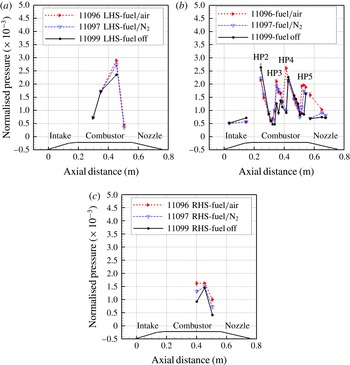
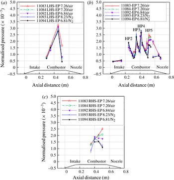
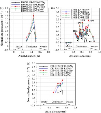
Measured wall centreline and off-centre pressure, normalised by the nozzle supply pressure, for fuel, low enrichment percentage and medium enrichment percentage are given in figures 8, 9, 10 respectively. Error bars represent one standard deviation on the measured steady state pressure. Engine geometry has also been included to aid in the analysis and discussion.
Normalised experimentally measured wall pressures for fuel-only cases: (a) left-hand side of combustor; (b) centreline; (c) right-hand side of combustor.

Normalised experimentally measured wall pressures for low enrichment levels: (a) left-hand side of combustor; (b) centreline; (c) right-hand side of combustor.

Normalised experimentally measured wall pressures for medium enrichment levels: (a) left-hand side of combustor; (b) centreline; (c) right-hand side of combustor.

Centreline pressure results clearly show the formation of the shock–expansion structure characteristic of RFS (Gardner et al. Reference Gardner, Paull and McIntyre2002; McGuire et al. Reference McGuire, Boyce and Mudford2008). In total, four shock impingements have been captured by the pressure sensors, which is in accordance with the engine design of five hot pockets/shock impingements. The fifth uncaptured shock impingement is located at the entrance to the combustion chamber where reliable pressure data were not recorded and coincides with the first hot pocket. Thus, shock impingements and hot pockets 2–5 (HP2–HP5) have been captured experimentally.
4.1. Fuel only
The effect that the mass of fuel injected has on pressure and shock structure in the absence of chemical activity is observed in the comparison of the fuel off and fuel/
 $\text{N}_{2}$
results in figure 8. From these, it is clear that fuel injection, and thus mass addition, affects both the pressure levels within the hot pockets and the shock–expansion structure itself, both documented features of mass injection in a RFS (Gardner et al.
Reference Gardner, Paull and McIntyre2002; McGuire et al.
Reference McGuire, Boyce and Mudford2008). Firstly, pressure levels within the centreline third and start of HP4 rises sharply with fuel injection (
 ${>}60\,\%$
and
 ${>}10\,\%$
respectively); however, no significant chemical activity is observed. This is evidenced by the invariance of the pressure between the reacting (fuel/air), non-reacting (fuel/
 $\text{N}_{2}$
) and fuel-off case over the expansion between the two shock impingements characterising the start of HP4 and HP5. Had significant combustion or chemical activity occurred with the reacting case (fuel/air) a sustained and significant pressure rise would have occurred over the last HP. As this is not evident, the results support the argument that no significant chemical activity or combustion occurred. Secondly, the peak, or shock impingement, location is seen to move upstream with fuel injection. This is particularly noticeable towards the rear of the combustion chamber in HP4 and HP5 where shock impingement moves upstream in the order of 13 mm with fuel addition, which is the spatial resolution of the pressure transducers. A pressure rise is also observed in the off-centre pressure measurements when fuel is injected. Again, mass injection and changed shock structure are considered to contribute to the off-centre measured pressure rise, as demonstrated in a recent numerical study by Capra et al. (Reference Capra, Boyce, Kuhn and Hald2015) on porous injection in a similar engine with the exact injector geometry tested in this study.
Although designed to be nominally 2D, examination of figure 8(a,c) clearly shows an asymmetry in the pressure within the engine, with higher pressure recorded on the left-hand side of the combustor. The engine contains a number of features that introduce slight asymmetry into the flow. Such features include small gaps in the assembly of the model which were minimised, filled and filed until smooth with the local surface, uneven wearing of the sharp leading edges and movement of the porous injectors. During experimentation, it was found that the injectors experienced a small but noticeable level of movement. Although remaining structurally sound, the injectors bowed and gradually moved relative to the holders. This movement was found to be different for each injector (top and bottom flow path side) thus further adding to the asymmetry of the measured pressure levels on the right- and left-hand side of the engine. The top injector bowed significantly, moving in the order of 1.5–2 mm in the centre but otherwise remained flush with the holder at the front and rear when viewed in the direction of flow. The bottom injector, located on the flow side where all pressure measurements were taken, experienced more asymmetrical movement. Initially mounted so a small recess (0.5 mm) existed between the injector holder and injector, the porous injector was found to move so that the left-hand side when viewed from the front protruded in the order of 0.5 mm at the front and approximately 1.0 mm at the rear. The right-hand side of the injector was also observed to move; however, the overall distance was less with the injector appearing to sit flush with the holder at the conclusion of these experiments. For the current set-up, it was assumed that the flow-through behaviour and the mass flow calculations were not affected by the flexing of the sample. It is important to note, and is emphasised, however, that for the same experimental set-up, including slight movement of the injectors, results from this study provide insight into the effect of adding oxygen to fuel prior to injection through porous injectors. Nevertheless, future injector components should be optimised for high mass flow rates while offering low pressure resistance and minimising flexural stresses.
Fuel-only shots shown in figure 8 provide evidence of very limited chemical (combustion) activity at the examined fuelling level of
 ${\it\Phi}=0.493$
and freestream conditions. This is illustrated in the small pressure rise over the non-reacting case within the fifth centreline hot pocket towards the rear of the engine. As the same level of fuel was injected for all cases, the additional observed pressure rise of the reacting case over the non-reacting case indicates an additional method of pressure rise beyond increase mass addition, namely heat release in supersonic flow (Anderson Reference Anderson2003). This increase, however, is small indicating that appreciable combustion has not been achieved when compared to the non-reacting case. Had significant combustion been achieved, much higher pressure within the last hot pocket would be present, together with higher pressure in the expansion regions when compared with the non-reacting case. Despite the lack of appreciable combustion, chemiluminesence imaging of the first 100 mm of the combustion chamber, as detailed by Brieschenk et al. (Reference Brieschenk, Capra, Lorrain, McIntyre and Boyce2012), confirmed the formation of radical farms containing significant OH levels for the reacting case, indicating that conditions for the combustion process to begin and radicals to be formed, were generated.
Evidence of ignition is also observed in the off-centre pressure measurements, where a small, but distinct, pressure rise at the third off-centre transducers was observed on each side of the combustion chamber. As these gauges are located further upstream compared with those centreline gauges that show a pressure rise, ignition appears to have started within the sidewall region and moved in, reaching the centre towards the rear of the combustor. Conclusive evidence of this ignition mechanism was not determined experimentally, but is consistent with results of a numerical study performed by Capra et al. (Reference Capra, Boyce, Kuhn and Hald2015) examining the ignition characteristics of porous fuel injection in a similar engine to the one of the present study.
Results from the fuel-only experiments indicate that, at the fuelling level examined, the engine is on the verge of achieving appreciable combustion levels with porous injection and therefore makes an excellent case study for investigating the benefits to be gained from oxygen enrichment. Based on these results, oxygen was added at two enrichment levels with the fuel prior to injection to determine if the observed borderline combustion scenario can be converted into one exhibiting sustained combustion.
4.2. Oxygen enrichment
Two levels of oxygen enrichment were achieved in the current series of experiments: a ‘low’ enrichment level, with an EP of
 $6.8\pm 5.3\,\%$
, and a ‘mid’ enrichment level with an EP of
 $10\pm 4.4\,\%$
. Results from these two enrichment levels provide insight into the trends of increasing oxygen-enriched fuel injection through mainstream porous injectors in scramjet engines.
The engine remained started at both enrichment levels, showing no evidence of combustion-induced separation on the inlet, as shown in the schlieren images in figure 11. All fuelling conditions resulted in attached oblique leading edge and fuel injection shocks characteristic of a stable and started intake shock structure. Had inlet combustion, or combustion-induced separation leading to engine unstart occurred, this shock structure would be significantly altered, with higher injection shock angles, separated regions and the formation of a normal, upstream moving shock observed. This is an important result as previous experiments performed by Portwood (Reference Portwood2006) on a similar engine investigating oxygen-enriched ethylene (
 $\text{C}_{2}\text{H}_{4}$
) with intake porthole injection demonstrated difficulties in engine starting with oxygen enrichment at a similar enthalpy (
 $3~\text{MJ}~\text{kg}^{-1}$
), at equivalence ratios greater than 0.08. Injection method and/or choice of fuel could both influence the favourable start behaviour observed in the present study over Portwood’s. A detailed investigation of the cause of unstart associated with oxygen enrichment through intake porthole injection, however, is outside the scope of this work and it is simply stated that the engine consistently started for the enriched porous fuel injection results reported in this paper.
Intake schlieren images of porous fuel injection with and without oxygen-enriched fuel. Flow is from left to right.

Normalised pressure for the low and medium oxygen-enriched shots, along the centreline and two off-centre locations, are shown figures 9 and 10 respectively. Pre-mixing oxygen with the fuel prior to injection increases the overall pressure levels within the engine; however, the overall shock structure within the engine was found to not be significantly altered.
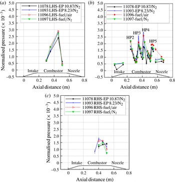
Normalised pressure measurements for non-reacting cases, oxygen-enriched, and fuel-only cases (nitrogen test gas): (a) left-hand side of combustor; (b) centreline; (c) right-hand side of combustor.

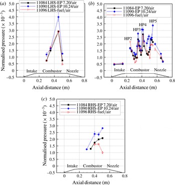
Normalised pressure measurements for reacting oxygen-enriched and fuel-only cases (air test gas): (a) left-hand side of combustor; (b) centreline; (c) right-hand side of combustor.

To demonstrate that the measured pressure rise with oxygen enrichment was a result of combustion, and not solely affiliated with the increase in mass injected into the engine, an enriched fuel case in a non-reacting test gas (nitrogen) at each enrichment level was performed. Centreline and off-centre pressure from these cases are shown in figure 12 together with both the non-reacting and reacting fuel-only cases. Suppressed combustion data shown in this figure represent the highest EP level achieved for an individual shot in the low- and mid-enrichment ranges. Although not truly a non-reacting case due to the presence of small levels of oxidiser within the engine, the equivalence ratios of 15 and 12 for the low- and mid-enrichment cases respectively, indicates that the injected fuel–oxidiser mix is too fuel rich to sustain noticeable chemical activity in a nitrogen test gas. Centreline pressure measurements for both oxygen enrichment cases confirm no significant combustion is achieved within the engine as a result of the enrichment process. This is evidenced by the similar pressure levels recorded for enriched and non-enriched fuel injection in a non-reacting test gas. Recorded pressure levels towards the rear of the right-hand side of the combustion chamber for non-reacting enriched fuel injection were found to be similar to, or higher than, the combusting fuel-only case. Limited ignition of the fuel and oxidiser, caused by the spread and mixing of the fuel/oxidiser mix towards the sidewalls and associated elevated temperatures associated with interaction of two boundary layers, is considered to be a potential cause of the observed pressure increase in this region. This cannot, however, be conclusively stated without additional analysis such as a detailed numerical reconstruction of the experiments. However, the argument for limited ignition and chemical activity, in the enriched shots into a non-reacting test gas near the sidewall, is consistent with the ignition and mixing characteristics of this engine as reported by Capra et al. (Reference Capra, Boyce, Kuhn and Hald2015).
Engine pressure with oxygen-enriched fuel injection into a reacting test gas is shown in figures 9 (low EP) and 10 (mid EP) and figure 13 which summarises the results from the no-, low- and mid-enriched combusting cases. Data selected for presentation in figure 13 represent the highest enrichment percentages achieved for both the low- and mid-enrichment cases. Although the results indicate that rigorous burning remains unlikely to have been achieved with enrichment due to the test condition and overall low equivalence ratio, it is clear that oxygen enrichment acts to enhance combustion over the limiting fuel-only case. This is seen along both the centre and off-centre locations where pressure was recorded.
Considering first the centreline results, the fuel-only case has an average normalised pressure of
 $1.5\times 10^{-3}$
rising slightly to
 $1.8\times 10^{-3}$
towards the rear where combustion is initiated. By adding a small amount of oxygen with the fuel, to give an EP of
 ${\approx}6.8$
, prior to injection, the measured mean normalised pressure was found to increase by approximately 20 % to
 $1.8\times 10^{-3}$
. The most noticeable increase in pressure, which also coincides with an observed slight change in shock structure, occurs between HP4 and HP5 at the rear of the combustion chamber. In this region, the recorded pressure remains elevated from the fuel-only case, particularly over the expansion between these hot pockets where an additional pressure peak is observed. A further increase of the EP to
 ${\approx}10$
increases the average engine (combustion chamber) normalised pressure by a further 22 %, compared to the low EP case and more than 40 % compared to the fuel-only case. All recorded (combustion induced) pressure rises associated with the enriched cases are seen to be greater than the EP. For example, consider the mid EP results where an EP of
 ${\approx}10$
was achieved. In this case, the heat release for the stoichiometric situation would be an additional 10 %, to first-order. In a constant area combustor case (as per the current study) this result translates directly as in increase in pressure rise. Thus, the similar percentage rises observed between enrichment level and pressure rise provides a useful observation regarding the physical effect of increased pressure rise in a constant area combustion chamber. Given that a constant amount of fuel was injected for all cases, enriched or not, it can be concluded that
 $\text{O}_{2}$
enrichment acts to promote more fuel consumption through combustion. The additional mixing achieved by injecting
 $\text{O}_{2}$
with the fuel and the injector size, where by the porous injector overs 44 % of the engine span, are considered likely to contribute to the observed combustion improvement.
This result is consistent with previous oxygen-enriched experiments by Razzaqi & Smart (Reference Razzaqi and Smart2011) but contradictory to those of Portwood (Reference Portwood2006) who for a similar engine observed no significant combustion chamber pressure rise with enrichment. Fuel (
 $\text{H}_{2}$
versus
 $\text{C}_{2}\text{H}_{4}$
), fuel injection method (porous versus porthole) and combustor length (380 mm versus 250 mm) were all different between the current study and that of Portwood, and it is believed that the combination of these factors results in significant combustion improvement with oxygen enrichment that was not observed in Portwood’s study.
The earlier onset of the observed pressure rise, along both the centre and off-centre locations, indicates that the point of ignition is likely to have moved upstream, although without a more spatially refined pressure transducer array, the exact location, and hence movement, of ignition cannot be conclusively determined.
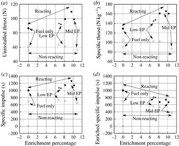
To demonstrate further that a higher level of combustion was achieved with enrichment, thrust, both uninstalled (
 $F$
) and specific, along with specific impulse (
 $I_{sp}$
) and enriched specific impulse (
 $I_{sp,en}$
) were calculated from recorded thrust nozzle pressures. These are shown in figure 14. Only three out of the five installed thrust nozzle pressure transducers gave reliable signals, one at the start of the nozzle and two at the rear, and these have been used to calculate the parameters shown. Uninstalled thrust was calculated by assuming the recorded centreline pressure was constant along the span (75 mm) of the engine and acted on a finite area of the nozzle taken to start/end halfway between installed transducers or the nozzle start/end where appropriate. Nozzle area where no reliable pressure data were recorded has been excluded from the analysis. Calculated thrust was then doubled to account for the top surface of the engine, which was not instrumented with pressure transducers. Due to these assumptions, the slight observed engine asymmetry, and the lack of full pressure recordings on the thrust nozzle, the reported thrust and specific impulse levels given in figure 14 are considered to under-predict the true level; however, they do indicate the trends of the effect that oxygen-enriched porous fuel injection has on engine performance. Standard definitions of specific thrust and impulse have been used (Heiser & Pratt Reference Heiser and Pratt1994) with the enriched specific impulse accounting for the additional injected mass according to
 $$\begin{eqnarray}I_{sp,en}=\frac{F}{g\left({\dot{m}}_{\text{H}_{2}}+{\dot{m}}_{\text{O}_{2},add}+{\dot{m}}_{\text{N}_{2}}\right)},\end{eqnarray}$$
where
 $g$
is gravitational acceleration (
 $9.81~\text{m}~\text{s}^{-2}$
).
(a) Uninstalled thrust; (b) specific thrust; (c) specific impulse; and (d) enriched specific impulse. Open symbols represent non-reacting cases and solid symbols indicate reacting cases: square, mid EP; triangle, low EP; circle, no EP; diamond, fuel off/air.

Similar thrust, specific thrust and specific impulse levels are obtained for the non-reacting cases irrespective of enrichment level. This result provides further evidence that the measured pressure increase within the combustion chamber in a reacting test gas is associated with combustion and, further, that oxygen enrichment enhances the level of combustion achieved. Oxygen enrichment is seen to increase the thrust and specific impulse over non-enriched cases to a level consistent with the enrichment percentage, with greater increases with the higher EP. This indicates a measurable and real advantage of engine performance improvement with oxygen enrichment. For example, consider the specific impulse. An EP of 6.8, corresponding to the low EP cases, results in a 7 % increase in
 $I_{sp}$
over a fuel-only case. This is increased to 18 % when EP is increased to 10. When specific thrust is considered, the measured increase is even greater at approximately twice the enrichment percentage. Similar findings were reported by Razzaqi & Smart (Reference Razzaqi and Smart2011) in a central strut injection, hydrogen fuelled scramjet engine where fuel and oxidiser (
 $\text{O}_{2}$
and
 $\text{N}_{2}$
at the same mix as the current study) were injected directly into the combustion chamber. In that study, oxygen enrichment was found to increase the specific impulse by as much as three times the enrichment percentage. In contrast to the current results, however, no discernible difference in performance between low and high EP was found, and this benefit was only seen in the ‘high altitude’ cases corresponding to altitudes 41.2 and 47.2 km and a flight Mach number of 11. At a ‘standard altitude’ of
 ${\approx}37~\text{km}$
and
 $M_{f}=11$
, which is similar to the equivalent flight conditions of this study, Razzaqi & Smart (Reference Razzaqi and Smart2011) reports only a small level of improvement in specific thrust with enrichment, and again no discernible performance difference with increasing enrichment levels.
Although thrust (uninstalled and installed) and specific impulse were found to increase with increasing oxygen enrichment for this series of experiments, the enriched specific impulse was found to decrease, as shown in figure 14(d). This result is in agreement with the findings of Razzaqi & Smart (Reference Razzaqi and Smart2011) and is a result of the inclusion of all injected mass being considered. The importance of these results is that the current experiments indicate that the amount of fuel being burnt is greater with oxygen enrichment (specific impulse, figure 14
c) which implies a greater level of fuel–oxidiser–air mixing is achieved, and that the overall temperature is getting hotter (specific thrust figure 14
b). Both of these are beneficial to overall vehicle performance and viability, but are achieved at the expense of weight. This is highlighted in the decrease in enriched specific impulse (figure 14
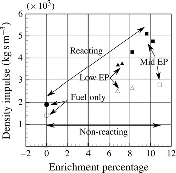
d), which considers all injected mass, not just fuel. When analysing the overall performance of the engine due to oxygen enrichment, however, it is important to consider all results presented in figure 14 together with the density impulse (
 $I_{sp,{\it\rho}}$
). Figure 15 plots the overall density impulse for fuel-off, fuel-only and enriched cases. The density impulse was calculated from
 $$\begin{eqnarray}I_{sp,{\it\rho}}=I_{sp}{\it\rho}^{n},\end{eqnarray}$$
where
 ${\it\rho}$
is the density of the fuel within the plenum chamber and a value of
 $n=0.7$
has been used, which is the maximum value suggested by Gordon (Reference Gordon1962).
Density impulse: symbols as figure 14.

Results in figure 15 show that the density impulse increases with enrichment. Thus, although the fuel/oxidiser mix is heavier, the results in figure 15 demonstrate that a smaller volume, and hence smaller physical tank, can be used to deliver the same density impulse to the vehicle. A similar argument (smaller tank, but heavier fuel) is often used to justify the selection of hydrocarbon fuels over hydrogen fuels (Pike Reference Pike1999). This selection, although practical from a vehicle packaging perspective, results in the use of a heavier fuel that has a smaller specific impulse and heat release potential. Using the same justification (smaller tank, but heavier fuel), it can be argued that the enriched hydrogen mixture offers greater potential than hydrocarbon fuel. This is because an enriched hydrogen mix will have a higher specific impulse, higher heat release potential (and thus thrust) and, by carrying oxygen, reduced mixing lengths and increased flight corridors, over hydrocarbon options.
5. Conclusion
Combustion and performance enhancements associated with oxygen-enriched fuel injection through oxygen-compatible porous CMC material in a RFS have been experimentally investigated using the T4 shock tunnel at the University of Queensland. A nominally 2D engine with intake fuel injection was tested at a stagnation enthalpy of
 $(3.93{-}4.25)\pm 3.2\,\%~\text{MJ}~\text{kg}^{-1}$
at an equivalent flight Mach number of 9.2–9.6. A constant hydrogen fuel mass flow rate of
 $8.89\pm 1.3\,\%~\text{g}~\text{s}^{-1}$
was maintained resulting in a mean
 ${\it\Phi}$
of
 $0.493\pm 3\,\%$
for all experiments. For safety reasons, a 75 %
 $\text{O}_{2}$
/25 %
 $\text{N}_{2}$
mixture was used as the oxidiser to enrich the fuel, with this ratio incorporated into all enrichment calculations. Two enrichment levels, low and mid, resulting in EP values of
 $6.8\pm 5.3\,\%$
and
 $10\pm 4.4\,\%$
respectively were tested together with a fuel-only case. Operating limits of the oxidiser flow system and porous injection material dictated these two EP levels respectively. For each fuelling condition, reacting and non-reacting experiments were performed as well as a fuel-off case in order to demonstrate that the measured pressure and thrust improvements were combustion related and were enhanced with enrichment.
The engine was found to remain started for all fuelling conditions, showing no evidence of intake combustion due to the enrichment of the fuel. With no enrichment, pressure results for the reacting case indicated that the engine was on the verge of achieving appreciable combustion, with a small but measurable increase in combustion chamber and thrust nozzle pressure over the non-reacting results. Oxygen enrichment was demonstrated to enhance the engine performance through increased combustion-induced pressure rise and increased specific thrust and specific impulse. All of these parameters were found to be improved with increasing oxygen enrichment to levels beyond the enrichment percentage, indicating a fuel–air mixing improvement beyond simply the added oxidiser to the fuel. This additional improvement in engine performance is attributed to the combination of the oxygen enrichment and the method of fuel delivery, namely porous injection. Porous injectors distribute the fuel/oxidiser mix further along the engine, homogeneously in all directions, compared with the more common porthole injection, thereby providing an additional method of promoting fuel/air mixing within the engine. Combined with oxygen enrichment, this acts to promote combustion performance of a RFS and thereby offers a potential mechanism to extend scramjet technology for use in access-to-space applications.
Acknowledgements
This work was funded by Australian Research Council grant (ARC DP120101009). The authors would like to thank Dr S. Razzaqi for her help with setting up and using the oxygen fuel system at UQ, Dr S. Brieschenk for the provision of schlieren images and shock angles, Mr P. Lorrain for assistance during experimentation, and all the T4 operators.