


INTRODUCTION
Inductive energy storage (IES) generators are used to obtain microsecond-duration mega-ampere currents in capacitor-to-inductor electrical discharges. Further electromagnetic (EM) power multiplication in vacuum is possible with application of different plasma technologies of magnetic flux compression/redistribution to a useful load with sharpening of the current pulse rise-time (Mesyats, Reference Mesyats2005) from typically 1–2 µs to 100–200 ns. Successful validation of these techniques would allow cost-effective and compact nanosecond EM pulse power for inertial confinement fusion and high energy density physics research (Matzen et al., Reference Matzen, Sweeney, Adams, Asay, Bailey, Bennett, Bliss, Bloomquist, Brunner, Campbell, Chandler, Coverdale, Cuneo, Davis, Deeney, Desjarlais, Donovan, Garasi, Haill, Hall, Hanson, Hurst, Jones, Knudson, Leeper, Lemke, Mazarakis, McDaniel, Mehlhorn, Nash, Olson, Porter, Rambo, Rosenthal, Rochau, Ruggles, Ruiz, Sanford, Seamen, Sinars, Slutz, Smith, Struve, Stygar, Vesey, Weinbrecht, Wenger and Yu2005), as compared to the pulse forming line design approach (Miller, Reference Miller1982). Alternative approach using the linear transformer driver technology (Kovalchuk et al., Reference Kovalchuk, Kharlov, Zherlitsyn, Kumpjak, Tsoy, Vizir and Smorudov2009) enabled to achieve ~100 ns rise time output pulse without intermediate pulse forming sections. Recently, conventional generators have also been used for direct microsecond magnetic compression of plasmas in radiation physics research, without intermediate stages of EM power conditioning (Labetsky et al., Reference Labetsky, Chaikovsky, Fedunin, Fursov, Kokshenev, Kurmaev, Oreshkin, Rousskikh, Shishlov and Zhidkova2006; Lassalle et al., Reference Lassalle, Roques, Mangeant, Loyen, Georges, Calamy, Cambonie, Laspalles, Cadars, Rodriguez, Delchie, Combes, Chanconie and Saves2007). In this latter case, the power multiplication is accomplished through conversion of the EM energy into kinetic/internal plasma energy and X-radiation.
In the methods of EM power conditioning with parallel connection of the plasma power multiplication element through vacuum convolutes (Bastrikov et al., Reference Bastrikov, Zherlitsyn, Kim, Kovalchuk, Loginov and Yakovlev1999; Chuvatin et al., Reference Chuvatin, Kokshenev, Aranchuk, Huet, Kurmaev and Fursov2006a), the nanosecond pulse power load is defined geometrically as a small volume (~few cc) downstream of the convolute. Similarly, for direct microsecond plasma acceleration/compression and further energy conversion (Labetsky et al., Reference Labetsky, Chaikovsky, Fedunin, Fursov, Kokshenev, Kurmaev, Oreshkin, Rousskikh, Shishlov and Zhidkova2006; Lassalle et al., Reference Lassalle, Roques, Mangeant, Loyen, Georges, Calamy, Cambonie, Laspalles, Cadars, Rodriguez, Delchie, Combes, Chanconie and Saves2007) the load inductance is also geometrically defined as that between the initial plasma position and the opposite current return conductor. In all these cases, the inductance of the load volume with high energy density, constant or varying in time, has typical maximum values of L d ~ 10 nH.
In the approaches to microsecond power conditioning, the time t 0 to the peak current provided by an IES generator should not considerably exceed the value of ~1–2 µs. Higher t 0 values result in poorer plasma power multiplication for physical and technological reasons that can be different for each method. Consider typical load current (LC) circuit for IES generators, if active losses are neglected, i.e., considers the discharge of a capacitor C 0 through an inductance L tot, so that the generator current is I0. The maximum I0 value is thus

where U 0 is the initial voltage on the capacitor and t 0 = π(L totC0)1/2/2 is the discharge current quarter-period. The inductance is conventionally divided here between that of a small-volume load inductance L d and that of the rest of discharge circuit, L 0, that we attribute to the generator, L tot = L 0 + L d.
If both L d and t 0 are specified, increase of the generator current for further power conditioning using either EM pulse shortening plasma techniques or energy conversion techniques is possible either though the increase of generator stored energy (0.5C0(U0)2) or though a decrease of the inductance L 0. On the other hand, at a given operating voltage U 0, the generator inductance value L 0 has a minimum value that is determined by the electric breakdown strength of dielectric-insulated or vacuum-insulated high voltage gaps in the current generator, as well as by the inductance of electrical connections between the larger-diameter (meters) initial energy storage and a smaller diameter, high energy density power conditioning plasma (centimeters). The specific value of L 0min(U 0) is defined by the architecture of the microsecond generator (Kovalchuk et al., Reference Kovalchuk, Kokshenev, Kim, Kurmaev, Loginov and Fursov1997; Lassalle et al., Reference Lassalle, Roques, Mangeant, Loyen, Georges, Calamy, Cambonie, Laspalles, Cadars, Rodriguez, Delchie, Combes, Chanconie and Saves2007), but commonly results in values not smaller than L 0 ~ 50–100 nH. This is referred to as an “irreducible” inductance.
It was recently suggested that with the above limitations on L d, t 0, and L 0, the increase of the current in high-energy-density volume L d is possible without the increase of the generator stored energy. This new method, the load current multiplier (LCM) introduced in Chuvatin et al. (Reference Chuvatin, Rudakov, Weber, Cadièrgues and Bayol2005), intentionally ensures the inequality L d ≪ L 0 by incorporating additional hardware with additional current paths through a convolute positioned as close as possible to the L d volume. First experimental testing of a dielectric-insulated LCM at moderate currents demonstrated considerable load current increase when compared to the direct discharge through L tot = L 0 + L d described by Eq. (1). Here we report first results on the development of a vacuum-insulated LCM at multi-mega-ampere currents allowing higher currents and higher current derivatives in the load without changing the generator's stored energy or architecture.
This technique, if experimentally validated for high vacuum pulsed power, would make possible generation of higher magnetic fields on existing IES generators both for fundamental studies of the field-plasma interaction in different power conditioning devises, and for useful applications, such as studies of material properties at high dynamic pressures or X-radiation production (Mesyats, Reference Mesyats2005; Matzen et al., Reference Matzen, Sweeney, Adams, Asay, Bailey, Bennett, Bliss, Bloomquist, Brunner, Campbell, Chandler, Coverdale, Cuneo, Davis, Deeney, Desjarlais, Donovan, Garasi, Haill, Hall, Hanson, Hurst, Jones, Knudson, Leeper, Lemke, Mazarakis, McDaniel, Mehlhorn, Nash, Olson, Porter, Rambo, Rosenthal, Rochau, Ruggles, Ruiz, Sanford, Seamen, Sinars, Slutz, Smith, Struve, Stygar, Vesey, Weinbrecht, Wenger and Yu2005; Labetsky et al., Reference Labetsky, Chaikovsky, Fedunin, Fursov, Kokshenev, Kurmaev, Oreshkin, Rousskikh, Shishlov and Zhidkova2006; Lassalle et al., Reference Lassalle, Roques, Mangeant, Loyen, Georges, Calamy, Cambonie, Laspalles, Cadars, Rodriguez, Delchie, Combes, Chanconie and Saves2007).
GIT 12 GENERATOR
Take as an example, the GIT12 IES generator described in Kovalchuk et al. (Reference Kovalchuk, Kokshenev, Kim, Kurmaev, Loginov and Fursov1997) with simplified electrical circuit presented in Figure 1. Figure 2 shows the generic GIT12 output section with a short-circuit load.
Simplified electrical circuit of GIT12 generator (see the text). The arrows denote directions of currents in the circuit.

Generic presentation of standard GIT12 output, see also Figure 1. Positions of Bdots measuring the current I 0 is also shown.

In Figure 1, C 0, R 0, and L 1 denote the effective capacitance, resistance, and inductance of 12 modules representing Marx generators connected in parallel to the central junction J in Figure 2. C 0 = 14.4 µF, L 1 = 89 nH. Marx generators are resistively dumped to limit fault currents and capacitor voltage reversal. R 0 value in Figure 1 is the sum of dumping resistances and of the other resistances of electrical contacts in the circuit of 12 modules, R 0 = 43 mΩ. L U is the large-inductance armature for mechanical support of the central junction unit, L U = 636 nH. L 2 is the experiment-dependent inductance of connection to the load, L 2 = 10 nH for the output geometry in Figure 2.
S is a closing switch representing the gas closing switches in 12 Marx generators. Previous studies on GIT12 showed that the best fit of experimental currents could be obtained when S represented a resistance added in series to R 0 and decreasing hyperbolically in time during 500 ns from the initial value 1 Ω to the final constant value of 10−4Ω.
The load is experiment-dependent on this generator and it is defined here as the volume above the A-A plane in Figure 2. The load is thus formed by the Ø 37/32 cm vertical coaxial line and by a 16-cm diameter short-circuit cylinder. The major part of the analysis in this paper treats the load as a constant inductance L d and constant resistance R d. L d = L d0 = 8.2 nH in Figure 2, and we assume R d ≈ 2 mΩ to be the resistance of electrical contacts.
The circuit of Figure 1 is described by the following set of equations:

where q is the charge on the capacitor C 0, I in0 ≡ dq/dt. Analytical solution of Eq. (1) is quite tedious and we do not present it here.
Rather, we neglect current in the mechanical support inductance, i.e., I U0 = 0 (L U → ∞), I in0 = I 0. We define L 0 ≡ L 1 + L 2, L tot ≡ L 0 + L d and R tot ≡ R 0 + R d. Eq. (2) then describes a simple RLC circuit with capacitance C 0, resistance R tot and inductance L tot, all connected in series, so we can rewrite it:

Solution of Eq. (3) is
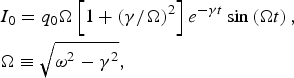
where q 0 = C 0U 0 is the initial charge, ω ≡ 1/(C 0L tot)1/2 and γ ≡ R tot/2L tot. The maximum current is achieved at t 0 = arctan(Ω/γ)/Ω. At the Marx charging voltage u 0 = 50 kV (U 0 ≡ 12u 0 = 0.6 MV) and with the generator and load parameters defined above, Eq. (4) yields the maximum current I 0max = 4.89 MA at t 0 = 1.68 µs.
For comparison, numerical solution of Eq. (2) with the switch S model described in the text accompanying Figure 1 (this solution is shown in Fig. 7 below) yields rather close values of I 0max = 4.6 MA at t 0 = 1.87 µs and corresponds well to the typical experimental result at this charging voltage of GIT12 firing into a short-circuit load (Labetsky et al., Reference Labetsky, Chaikovsky, Fedunin, Fursov, Kokshenev, Kurmaev, Oreshkin, Rousskikh, Shishlov and Zhidkova2006).
Finally, as discussed in the Introduction, the inductance L 0 is irreducible (at least the L 1 part, corresponding to the internal inductance of GIT12 modules in Fig. 1) and higher currents I 0 upon Eq. (4) seem to be possible only if the generator charging voltage is increased (the maximum measured current of 6.2 MA is reported in Kovalchuk et al. (Reference Kovalchuk, Kokshenev, Kim, Kurmaev, Loginov and Fursov1997) for u 0 = 70 kV charging voltage).
VACUUM LCM ON AN IDEAL IES GENERATOR
Let us now show how higher currents are achievable. Taking as reference the GIT12 output section above the A-A plane in Figure 2, consider additional hardware as shown in Figure 3. This is a current multiplier configuration corresponding to Figure 1b in Chuvatin et al. (Reference Chuvatin, Rudakov, Weber, Cadièrgues and Bayol2005). The LCM is formed by two coaxial, concentric toroids. Inductance of the inner toroid L (magnetic flux extruder) should be large compared to the load inductance Ld. L here is a large vacuum volume without magnetic cores, I is the current inside the volume. I g and I d are the generator and load currents in the modified circuit. Bypass inductance between the toroids is L v.
LCM arrangement in vacuum on a pulse power generator when taking as example the initial output configuration of Figure 2. Dots and dashes denote contours for definition of the circuit equations.

The toroids are connected to the load through a convolute C. From preliminary analysis, the general recipe for substantial current increase in the load is to position the convolute C as close as possible to the high energy density volume L d in order to have L d ≪ L 0. One should note here that in contrast with standard configuration of Figure 2, where the L d0 volume definition was somewhat arbitrary and depended on the specific high energy density experiment, the LCM configuration unambiguously defines the load as the overall volume downstream of the LCM convolute.
Let us analyze electrical behavior of the added hardware. To start with, consider this hardware to be powered by an ideal LC generator, i.e., which has the inductance L 0, capacitance C 0 and does not have resistance in the circuit. This is equivalent to L U → ∞ and I in = I g in Figure 1. We totally neglect dissipation in the circuit, R 0 = R d = 0, and consider L d = constance.
Now, the dotted contour in Figure 3 includes C 0 and L 1 in the generator circuit and all the volumes shown in Figure 3, i.e., L 2, L v, L, and L d. Flux conservation inside this contour corresponds to the equation (L 0 ≡ L 1 + L 2):

Then, the magnetic flux inside the dashed contour in Figure 3 is equal to LI – L dI d. This flux is initially zero because the currents are zero. This flux then remains zero during the capacitor discharge because we neglected dissipation anywhere. Therefore, at any time moment,

For the chosen directions of currents in Figure 3, the in-flowing and out-flowing currents into the convolute posts C are 2I g and I + I d accordingly. The current continuity at the convolute C thus implies

Eqs. (6) and (7) provide us with the load-to-generator current ratio in the new hardware:

Therefore, in the limit L ≫ L d the load current in the load is twice the generator current.
In turn, using Eqs. (7) and (8), Eq. (5) can be rewritten in the following form to calculate I g:

where

so that I gmax = 2U 0t d/πL *tot is the maximum generator current in Eq. (9) and the peak generator and load current time t d is now defined as t d = π(L *tot × C 0)1/2/4. The maximum generator current amplitude Ig max does not change very much with respect to the no-LCM current I 0max of Eq. (1) under condition L v + 4LL d/(L + L d) ≪ L 0.
To investigate potential gain in the load current amplitude with respect to the standard LC circuit, let us introduce a normalized peak load current idmax ≡ I dmax/I 0max and a normalized current rise-time τ ≡ t d/t 0. We also normalize all the inductances to the generator inductance L 0, x ≡ L/L 0, d ≡ L d/L 0 and we also define a new parameter χ ≡ L/L v. Eqs. (1), (8), and (9) result in

These relationships coincide with those of Eq. (11) in Chuvatin et al. (Reference Chuvatin, Rudakov, Weber, Cadièrgues and Bayol2005) except now we do not neglect the bypass inductance Lv between the toroids (Fig. 3). Indeed, high current multiplication coefficients κ in Eq. (8) are achievable at high extruder cavity inductance L. At the same time, the interelectrode gaps between the toroids cannot be made too small to avoid electron current leakage and shortening of the gaps by plasma formed on electrode surfaces at high current densities. Therefore, the higher L, the higher L v and concrete LCM design corresponds to some fixed ratio χ.
If the load current rise-time is constrained, one could introduce normalized load current with LCM at the time moment t 0, when the no-LCM current is maximum (see Eq. (1)). We use the solution of Eq. (9) and the relationship of Eq. (8) to obtain I d(t 0), using Eq. (11):

At a given χ, we have i dmax → 0 and i d → 0 in Eqs. (11) and (12) both for x → 0 and for x → ∞, so that there exists an optimum value of the extruder inductance x = L/L 0 corresponding to the maximum i dmax(x) and i d(x). The LCM design procedure thus should consist in proper choice of the large inductance L for a given load inductance L d when the load-to-generator current ratio is maximized and when the parasitic inductance L v added to the generator inductance L 0 in Eq. (9) does not decrease considerably the generator current amplitude with respect to I 0max from Eq. (1). Figure 4 illustrates this logic for several dimensionless load inductances d and several fixed ratios χ.

The values of i dmax, i d, and τ depending on the normalized large extruder cavity inductance x ≡ L/L 0 are calculated in Figure 4 for different normalized load inductances d ≡ L d/L 0 and for different extruder-to-bypass inductances ratios χ ≡ L/L v (inserts in Fig. 4).
The result of Figure 4 is that the values x = 1–2 could be chosen as those giving maximum possible i dmax and i d for the considered normalized load inductances. Again, the load currents with LCM i dmax and i d refer, respectively, to the new maximum achievable amplitude and to the new load current value taken at t = t 0, where t 0 is the current rise-time in the standard configuration before changes.
The peak load current time with LCM corresponding to x = 1–2 increases by 20–40%, τ = 1.2–1.4 in Figure 4a. Lower x values correspond to higher current leakage I in the extruder volume, Eq. (7), and lower current into the load, Eq. (8). In turn, too high x values at fixed χ ≡ L/L v correspond to high parasitic inductance L v added to the generator inductance in Eq. (9), and to the decrease of the generator and load currents. Also, relatively high load inductances, e.g., d = 0.4 or L d = 0.4L 0 in Figure 4, considerably increase L tot* and decrease the generator current in Eq. (9), so that application of the LCM technique does not provide considerable gain any more (i dmax and i d become close to unity). This is why the recommendation of Chuvatin et al. (Reference Chuvatin, Rudakov, Weber, Cadièrgues and Bayol2005) was to position the LCM convolute close to the L d volume in order to satisfy in general the inequality d ≪ 1, L d ≪ L 0.
Thus, Figure 4 allows preliminary parametric analysis of LCM operation for an ideal LC generator, i.e., without active losses, and suggests L = 1–2 L 0 for L d = 0.1–0.4 L 0 and for the considered range of extruder-to-bypass inductances ratios χ.
DESIGN AND TESTING OF A VACUUM LCM ON GIT12
We turn now to the LCM analysis and design for the GIT12 generator, when losses in damping resistors, R 0, and possibly in the load, R d, are present. The currents I in0, I U0 and I 0 now change in the circuit of Figure 1 because we modify the output A-A, so we denote them I in, I U and I g accordingly.
The first two equations in the system Eq. (2) do not change:

We use the same contours as in Figure 3 for Eqs. (5) and (6) but now include the load resistance R d. Eqs. (5) and (6) are now replaced by

The system (13, 14), together with the current continuity condition (7) completely describes LCM operation with the GIT12 circuit.
As for the case of Eq. (2), a simple analytical solution can be obtained if we neglect current in the mechanical support inductance, i.e., L U → ∞, I U → 0, I in ≈ I g. This allows us to simplify Eq. (13) and the first equation in (14), cf. Eq. (5):

where again L 0 ≡ L 1 + L 2.
If we now assume I d = κI g, κ = const, in Eqs. (7) and (15) and in the second equation of (14), we obtain the approximate equations:

which has the same solution as that of Eq. (3), i.e., has the form of Eq. (4) but with new coefficients ω ≡ 1/(C 0L tot*)1/2 and γ ≡ R tot*/2L tot*. Approximate solution for I g and I d can be then obtained here using Eq. (8) for the current multiplication coefficient κ, which is true if the magnetic flux dissipation in the load can be neglected in Eq. (8); i.e., if R d∫Iddt << L dI d.
This analytical solution is applicable to IES generators that have damping resistance R 0 but where the current in mechanical support inductance L U is totally neglected, I U ≪ I g. Eq. (16) with the corresponding solution (4) can be then used to calculate new generator and load currents analytically when the LCM technique is applied.
However, approximation IU → 0 used in Eqs. (13) and (14) for obtaining Eq. (15) and analytical solution of Eq. (16) cannot be warranted in advance for the GIT12 generator with an LCM because inductance and resistance downstream of L U become higher when compared to the standard configuration of Figures 1 and 2. Indeed, these values were L 2 + L d and R d accordingly in Eq. (3), while they become L 2 + L v + 2κL d and 2κR d in Eq. (16). This may lead to an increased current I U now becoming non-negligible.
Therefore, rather than using an analytical solution of Eq. (16), let us solve the system (13, 14) numerically in order to perform the same analysis as in Figure 4. We take the parameters of the GIT12 circuit, i.e., C 0 = 14.4 µF, R 0 = 43 mΩ, L 1 = 89 nH, L U = 636 nH, L 2 = 10 nH, and the switch S as modeled and explained in the text accompanying Figure 1. At t = 0 the currents are zero and q = C 0U 0, U 0 = 0.6 MV (u 0 = 50 kV charging voltage). We now assume R d = 2 mΩ and we numerically solve Eq. (2) for the basic GIT12 configuration of Figure 2 and Eqs. (130 and (14) for the LCM configuration of Figure 3. For a given load inductance L d, we vary the extruder inductance L. For each L and for given values of χ ≡ L/L v, we then calculate the maximum load current I dmax and the load current at t = 1 µs, I d1µs. Values of the load current at t = 1 µs are useful for the experiments where the current rise-time is constrained (Bastrikov et al., Reference Bastrikov, Zherlitsin, Kim, Kovalchuk, Loginov and Yakovlev1999; Labetsky et al., Reference Labetsky, Chaikovsky, Fedunin, Fursov, Kokshenev, Kurmaev, Oreshkin, Rousskikh, Shishlov and Zhidkova2006; Chuvatin et al., Reference Chuvatin, Kokshenev, Aranchuk, Huet, Kurmaev and Fursov2006a; Lassalle et al., Reference Lassalle, Roques, Mangeant, Loyen, Georges, Calamy, Cambonie, Laspalles, Cadars, Rodriguez, Delchie, Combes, Chanconie and Saves2007).
The result of the above procedure is shown in Figure 5. Solid curves in this figure are numerical solutions of Eqs. (13) and (14) for the LCM configuration of Figure 3. Dashed lines are numerical solutions of Eq. (2) for the basic GIT12 configuration of Figure 2, shown for comparison.
(Color online) (a) Dependence of the maximum load current I dmax on the extruder inductance L for load inductances L d of 10, 20, and 30 nH and for several values of χ ≡ L/L v (inserts). (b) The same dependencies on the extruder inductance L for the load current at t = 1 µs, I d1µs.

Interestingly, recommendations of Figure 5 for a realistic electrical circuit with active losses and additional inductance L U practically coincide with those from the dimensionless analysis of Figure 4 for an ideal IES generator. For GIT12 which has L 0 ≡ L 1 + L 2 ≈ 100 nH a noticeable gain in I dmax and I d1µs with respect to the no-LCM case is expected for L d = 10–20 nH (d = 0.1–0.2), L = 100–200 nH (x = 1–2), and for χ ≡ L/L v = 5–10.
Consider an intermediate value of χ = 7. The minimum bypass volume L v in Figure 3 is then defined by the minimum interelectrode gap sizes Δ that would still allow magnetic insulation in the corresponding vacuum lines. On GIT12, however, the main constraint on the Δ value came from the mechanical precision achievable on this generator, so that the minimum gap could not be made smaller than 1.5 cm. We note that this value is much larger than that which would suffice to ensure magnetic self-insulation; hence it could be made considerably smaller, thereby further decreasing the bypass inductance L v, if greater mechanical precision were possible in the alignment of the vacuum lines.
Taking into account the above consideration and searching for L values in the range 100–200 nH with χ = 7 resulted in the hardware design shown in Figure 6. The chosen gap sizes in the bypass vacuum lines L v1, L v2, and L v3 are Δ1 = 2 cm, Δ2 = 2.5 cm, and Δ3 = 1.5 cm accordingly. In this design, L = 133 nH, L v1 = 2.7 nH, L v2 = 6.6 nH, L v3 = 9.6 nH, so that L v ≡ L v1 + L v2 + L v3 = 18.9 nH (χ = 7). The convolute C is formed by 12 posts having Ø 2.5 cm diameter and connecting the LCM extruder to the ground electrode through corresponding holes. The inductive load includes the inductances of 16-cm diameter short-circuit cylinder, of Ø 37/32 cm vertical coaxial line (see Fig. 2) and of the additional convolute inductance, L d = 10 nH.
LCM hardware (in scale) realized on GIT12 upon the suggested design criteria. I gm and I dt denote positions of the generator current measurements, Igt = I gm in the experiments. I d is the load current measurement. Other notations are the same as in Figures 2 and 3.

Experimental validation of this LCM design is demonstrated in Figure 7. Experimental currents are close to the numerical solution of the system (13, 14) for the generator and LCM parameters described above and for u 0 = 49 kV charging voltage. Deviation of the experimental load current from its numerical value near the maximum could be attributed either to the measurement uncertainty or to current losses in the LCM convolute. This requires further investigation.
Solid lines: measured generator and load currents, I g and I d, and the experimental ratio κ = I d/I g in GIT12 shot with LCM from Figure 6 at u 0 = 49 kV charging voltage. Dashed lines: numerical solution of the system (13, 14) for I g, I d, and κ, L d = 10 nH, u 0 = 49 kV. Dotted line I 0 is the numerical solution of Eq. (2) for standard GIT12 operation without LCM, L d0 = 8.2 nH, u 0 = 49 kV.

The load current amplitude is increased from I 0max = 4.6 MA at t 0 = 1.87 µs in the standard GIT12 configuration of Figure 2 to I dmax = 6.43 MA at t d = 2.0 µs in the LCM configuration of Figure 6. The measured load-to-generator currents ratio at t = t d is κ = 1.73. In turn, the load current at t = 1 µs is increased from I 01µs = 3.37 MA to I d1µs = 4.4 MA. These values correspond to a 70% increase of the magnetic pressure at the load radius of 8 cm.
The main purpose of Figure 8 is to illustrate that this current increase could be possible on standard (no-LCM) IES generators only through a considerable increase (by ≈ 90%) of the generator stored energy. Indeed, we take Eq. (2) with GIT12 parameters defined by the nearby text and solve it numerically for gradually rising voltages u 0 until the solution amplitude I 0max reaches the experimentally measured peak load current I dmax = 6.43 MA. As shown in Figure 8, this becomes possible at u 0 = 68 kV, i.e., at the initial generator stored energy of E 0 = 4.8 MJ instead of u 0 = 49 kV with E 0 = 2.5 MJ when we use the LCM technique.
(Color online) Red: experimental load current from Figure 7 and experimental load power W d. Green: load current from Figure 7 and load power W d0. Blue: load current and power from numerical solution of Eq. (2) for standard GIT12 output in Figure 2 when the charging voltage is increased to u 0 = 68 kV in order to achieve the same current amplitude as in the LCM experiment.

Figure 8 also shows the achieved enhancement of EM power into the load which is defined as W d0 ≡ L d0I 0 × dI 0/dt in nominal GIT12 output and as W d ≡ L dI d × dI d/dt when the arrangement of Figure 6 is installed, L d0 = 8.2 nH and L d = 10 nH. At the unchanged charging voltage u 0 = 49 kV, W d0 ≈ 100 GW, and W d ≈ 230 GW that corresponds to a 130% increase of the electromagnetic power into a constant inductance load on this generator. Such a load power multiplication can be of importance for further application of power multiplication concepts.
As discussed in the Introduction, microsecond IES generators are usually coupled to different power conditioning devices. If an LCM is incorporated as a part of the IES generator, different techniques for further power multiplication are suggested and studied analytically elsewhere (Chuvatin et al., Reference Chuvatin2006b). In particular, these techniques allow resistive or inductive opening switches upstream or downstream of the LCM convolute, as well as a controlled abrupt increase of the LCM extruder inductance (Chuvatin et al., 2006b). We defer detailed discussion of these techniques in the configuration of Figure 6 on GIT12 for a later publication.
At the same time, the validated LCM can also be used directly with imploding plasma loads, allowing further power multiplication through EM-to-kinetic/internal/radiation energy conversion (Labetsky et al., Reference Labetsky, Chaikovsky, Fedunin, Fursov, Kokshenev, Kurmaev, Oreshkin, Rousskikh, Shishlov and Zhidkova2006; Lassalle et al., Reference Lassalle, Roques, Mangeant, Loyen, Georges, Calamy, Cambonie, Laspalles, Cadars, Rodriguez, Delchie, Combes, Chanconie and Saves2007). To illustrate this, we add in series to the constant inductance L d or L d0, with or without LCM, a variable part L d(t) = 2h × ln[r 0/r(t)] of a perfectly conducting infinitively thin cylindrical shell having the height h = 2 cm, the initial radius of r 0 = 8 cm, as in Figure 2, and the time-dependent radius r(t).
We then complete Eqs. (13) and (14) (Fig. 2) or Eq. (2) (standard GIT12) by the equation of motion of this thin shell accelerated by the magnetic field of the load current, I d or I 0, and having mass m shell:

To represent a generic microsecond experiment we vary m shell in order to have the implosion time equal to 1 µs. We also reduce the constant inductance between the LCM convolute and the shell to L d0 = L d = 5 nH. When the shell radius r(t) reaches the value of 0.3 cm, we calculate the kinetic energy E k = ½m shell(dr/dt)2 at this radius and then stop the shell.
As shown in Figure 9, the designed multiplier allows us to increase the shell kinetic energy from 80 to 130 kJ in microsecond implosions that, in turn, would allow increase of the soft X-ray power if the time of kinetic-to-radiated energy conversion remains were unchanged.

CONCLUSIONS
In conclusion, we have presented a design procedure for constructing vacuum load current multipliers without magnetic core for mega-ampere pulse-power. The design criteria allow a specific engineering hardware realization on the GIT12 microsecond IES generator. Experimental validation of this design resulted in approximately 40% increase of the peak load current, 95% increase of the maximum magnetic pressure at 8 cm radius, and in a 130% increase of electromagnetic power into constant-inductance load. The same result could be possible on GIT12 only through almost doubling of the initial stored energy.
ACKNOWLEDGMENTS
The authors would like to thank N.E. Kurmaev and F.I. Fursov for the assistance in manufacturing and tests of the LCM on GIT12. This work was supported by DGA/UM NBC, France and by CNRS, France.



