1 Introduction
The dynamic behaviour of encapsulated microbubbles, also known as contrast agents, plays a key role in novel biomedical applications involving ultrasound, among which the most important and promising ones are targeted drug delivery and the medical imaging of vital organs. In the former case, using an appropriate acoustic disturbance, encapsulated microbubbles that carry drugs are attached to the affected site and then ruptured (Ferrara, Pollard & Borden Reference Ferrara, Pollard and Borden2007). In the latter application, gas-filled microbubbles are used which are able to enhance the ultrasound backscatter and contrast, in comparison with the acoustic signal from nearby tissue, thus producing high-quality images (Kaufmann, Wei & Linder Reference Kaufmann, Wei and Linder2007) as a result of their nonlinear nature as sound scatters.
Upon their application in medical imaging or drug delivery techniques, contrast agents will typically interact with a nearby boundary and emit sound signals. Nevertheless, it is of interest to study their response in an unbounded medium in order to examine the stability of static configurations that exhibit different degrees of deformation as a result of the anisotropic nature of elastic stresses (Knoche & Kierfeld Reference Knoche and Kierfeld2011; Lytra & Pelekasis Reference Lytra and Pelekasis2014), and to assist shell characterization studies where coated bubbles are subjected to sonication in containers whose dimensions are much larger than their radius (Church Reference Church1995; Shi & Forsberg Reference Shi and Forsberg2000; Van der Meer et al. Reference Van der Meer, Dollet, Voormolen, Chin, Bouakaz, de Jong, Versluis and Lohse2007), where deformed shapes are reported (Marmottant et al. Reference Marmottant, van der Meer, Emmer, Versluis, de Jong, Hilgenfeldt and Lohse2005; Overvelde Reference Overvelde2010) using optical imaging techniques of freely pulsating coated microbubbles. In particular, when lipid monolayers comprise the shell that encloses the gas bubble, characterization studies that provide estimates of shell elasticity and viscosity based on acoustic measurements exhibit significant variation in the elasticity modulus and shell viscosity they provide (Marmottant et al. Reference Marmottant, van der Meer, Emmer, Versluis, de Jong, Hilgenfeldt and Lohse2005; Van der Meer et al. Reference Van der Meer, Dollet, Voormolen, Chin, Bouakaz, de Jong, Versluis and Lohse2007; Overvelde Reference Overvelde2010). This failure to provide reliable viscoelastic shell properties is often associated with compression-only behaviour where lipid monolayer shells are seen to pulsate mainly in the compression phase of their radial time series (De Jongo et al. Reference De Jong, Emmer, Chin, Bouakaz, Mastik, Lohse and Versluis2007), while exhibiting significant shape distortion (Marmottant et al. Reference Marmottant, van der Meer, Emmer, Versluis, de Jong, Hilgenfeldt and Lohse2005; Overvelde Reference Overvelde2010). The latter response is counter-intuitive since lipid monolayer shells exhibit a strain-softening behaviour when subjected to acoustic disturbances (Tsiglifis & Pelekasis Reference Tsiglifis and Pelekasis2008; Thomas et al. Reference Thomas, Looney, Steel, Pelekasis, Mcdicken, Anderson and Sboros2009; Katiyar & Sarkar Reference Katiyar and Sarkar2011), as a result of the reduction in area density of the lipid monolayer shell with increasing interfacial area, which amounts to a preferential excursion from equilibrium during expansion (De Jongo et al. Reference De Jong, Emmer, Chin, Bouakaz, Mastik, Lohse and Versluis2007; Tsiglifis & Pelekasis Reference Tsiglifis and Pelekasis2008), especially at large sound amplitudes.
An interesting aspect of compression-only behaviour of lipid shells pertains to the shape deformation that is typically observed when optical observations of the microbubble shape are available along with the radial time series (Marmottant et al. Reference Marmottant, van der Meer, Emmer, Versluis, de Jong, Hilgenfeldt and Lohse2005; Overvelde Reference Overvelde2010). This effect was associated with shell buckling in the latter studies without, however, introducing shell bending resistance or providing a relevant parametric study of the static response of lipid shells. Such a study, performed by Marmottant et al. (Reference Marmottant, Bouakaz, de Jong and Quilliet2011) for the case of polymeric shells, focuses on the onset of wrinkled three-dimensional shapes without providing a detailed bifurcation diagram. The static response of lipid shells is known to be different from that of polymeric shells (Lytra & Pelekasis Reference Lytra and Pelekasis2014), but the details of static equilibrium are not known, nor is the stability of the emerging shapes. The present study constitutes a first effort in the direction of obtaining detailed bifurcation diagrams of lipid and polymeric shells, along with the corresponding stability characteristics, in order to identify buckling events in available acoustic measurements, particularly so for the compression-only response pattern of lipid shells, and assess their effect on shell parameter estimation.
Numerical simulations of pulsating coated microbubbles with the boundary element methodology (Tsiglifis & Pelekasis Reference Tsiglifis and Pelekasis2013), when potential flow is considered in the surrounding liquid, recover a tendency for preferential excursion from equilibrium during compression due to nonlinear interactions between emerging shape modes during compression, as a manifestation of harmonic or subharmonic excitation (see also Tsiglifis & Pelekasis (Reference Tsiglifis and Pelekasis2011) for an extensive analysis of this mechanism of shape mode excitation of coated microbubbles) and the breathing mode of pulsation; the latter term refers to volume pulsations of the bubble. Nevertheless, the extent of the compression amplitude obtained by the simulations performed in the latter study was smaller than the one reported from optical measurements. The effect of pre-stress was introduced in order to enhance the onset of shape pulsations for lower sound amplitudes. However, in both cases the calculated deviation from equilibrium in favour of compression that was captured was not comparable with the measured values. Further increase of the sound amplitude accelerated the onset of dynamic buckling that led to bubble breakup before any significant mode interaction took place.
In the present study the dynamic behaviour of a contrast agent is investigated in an unbounded flow when the viscous forces of the surrounding liquid are also accounted for. According to static analysis (Knoche & Kierfeld Reference Knoche and Kierfeld2011; Lytra & Pelekasis Reference Lytra and Pelekasis2014) encapsulated microbubbles may reach a static non-spherical equilibrium state when subjected to step change disturbances. We are interested in examining the dynamic response of coated microbubbles to such disturbances and investigate the possibility for a static solution. In this context, the relative importance of shell and liquid viscosity in controlling the dynamics towards static equilibrium must be ascertained, since previous numerical studies assuming potential flow conditions (Liu et al. Reference Liu, Sugiyama, Takagi and Matsumoto2011; Tsiglifis & Pelekasis Reference Tsiglifis and Pelekasis2013), or taking into account the viscosity of the surrounding fluid (Liu et al. Reference Liu, Sugiyama, Takagi and Matsumoto2011), focus on the effect of shell and liquid viscosity, respectively. Furthermore, it is important to study the response of contrast agents to greater disturbances in the far-field pressure and determine whether jet formation occurs, as is the case with gas-filled bubbles (Blake et al. Reference Blake, Hooton, Robinson and Tong1997) in the vicinity of a solid boundary. The latter type of bubbles are known to collapse via jet formation and impact that typically leads to multiply connected bubbles, i.e. toroidal and satellite bubbles (Blake et al. Reference Blake, Hooton, Robinson and Tong1997, Reference Blake, Keen, Tong and Wilson1999). In particular, it is of interest to identify possible collapse scenarios that are relevant to coated microbubbles, and distinguish them from gas-filled bubbles.
For the case of encapsulated bubbles, there are experimental studies which report that the presence of a nearby boundary may accelerate growth of interfacial instabilities and instigate phenomena such as jet formation and, finally, collapse of the bubble (Zhao, Ferrara & Dayton Reference Zhao, Ferrara and Dayton2005; Vos et al. Reference Vos, Dollet, Bosch, Versluis and de Jong2008; Chen et al. Reference Chen, Kreider, Brayman, Bailey and Matula2011). The above experimental studies examine the situation with the coated microbubble pulsating in response to an acoustic disturbance, in the vicinity of a boundary. In this fashion, microbubble shapes that are asymmetrically deformed in the direction perpendicular to the boundary surface were captured (Vos et al. Reference Vos, Dollet, Bosch, Versluis and de Jong2008) while jet formation was observed in the compression (Zhao et al. Reference Zhao, Ferrara and Dayton2005) and expansion phase of the pulsation (Chen et al. Reference Chen, Kreider, Brayman, Bailey and Matula2011), respectively. In the present study, the possibility for similar phenomena to develop will be investigated, for coated microbubbles that are subject to a step change in the far-field pressure. In this case, shell elasticity, viscosity and bending offer many alternatives for redistributing surface energy at static equilibrium (Church Reference Church1995; Lytra & Pelekasis Reference Lytra and Pelekasis2014), and jet formation may not be a viable dynamic route. Furthermore, elastic shells subject to a uniform external pressure load are known to exhibit static shapes in their post-buckling behaviour that exhibit contact (Knoche & Kierfeld Reference Knoche and Kierfeld2011). In the present study it is of interest to investigate the possibility that formation of contact regions arises during the dynamic response to a step change in pressure, which leads to static equilibrium without jet formation.
In the case of free gas bubbles the spherical configuration is the only possible static shape in the absence of field forces or acoustic disturbances, and shape deformation, jet formation, and breakup constitute very common dynamic responses. Potential flow solvers employing the boundary integral method provide a very accurate description of the dynamic response of pulsating, deforming and/or collapsing bubbles provided by experiments, even in the absence of nearby boundaries (Lauterborn & Bolle Reference Lauterborn and Bolle1975; Dear & Field Reference Dear and Field1988; Pelekasis & Tsamopoulos Reference Pelekasis and Tsamopoulos1993a ,Reference Pelekasis and Tsamopoulos b ; Blake et al. Reference Blake, Hooton, Robinson and Tong1997, Reference Blake, Keen, Tong and Wilson1999). The influence of viscosity on the dynamic response of an initially elongated gas bubble in an unbounded flow, subject to internal overpressure, was studied by including weak viscous effects of the surrounding fluid via integration of the equations of motion across the boundary layer that is formed adjacent to the bubble interface (Tsiglifis & Pelekasis Reference Tsiglifis and Pelekasis2007). In this fashion, jet formation and breakup were captured for sufficient initial elongation and internal overpressure levels, below which jet formation was suppressed and the bubble eventually retracted to assume a spherical shape as a result of viscous damping. Simulations of this flow arrangement are repeated here as benchmark calculations. The effect of viscous dissipation on the collapse of a gas bubble that pulsates near a solid boundary has also been accounted for by Popinet & Zaleski (Reference Popinet and Zaleski2002), by solving the axisymmetric Navier–Stokes equations with free surface boundary conditions on the bubble interface. The numerical method was based on a finite volume formulation using both a fixed grid and a front tracking approach while the free surface was simulated using surface points connected with cubic splines. Thus, jet formation and rebound were captured and it was concluded that the jet impact velocity decreases as viscosity increases until, below a certain critical Reynolds number, jet impact was impossible.
Extensive numerical simulations of the dynamic response of contrast agents are not available in the literature, owing largely to uncertainties regarding proper modelling of the shell, especially in the case of phospholipid shells. Furthermore, the degree to which potential flow considerations can sufficiently capture the dynamic behaviour of deforming contrast agents is not fully understood. Qin & Ferrara (Reference Qin and Ferrara2006) developed a lumped parameter model as a means to incorporate elastic effects, mainly in the surrounding vessel, in order to study the acoustic response of a coated microbubble that pulsates in a compliant microvessel. They were thus able to calculate the stresses that develop on the microvessel wall as result of the pulsating motion, which was also seen to increase the permeability of the vessel. More recently, numerical studies were conducted to address the above issues via the finite volume (Liu et al. Reference Liu, Sugiyama, Takagi and Matsumoto2011) and boundary integral method (Tsiglifis & Pelekasis Reference Tsiglifis and Pelekasis2013) as a means to obtain a more detailed description of the velocity field in the surrounding fluid but also the elastic stresses on the coating. In particular, Liu et al. (Reference Liu, Sugiyama, Takagi and Matsumoto2011) explored numerically the shape oscillations in an unbounded flow of an encapsulated microbubble that obeys the Mooney–Rivlin constitutive law by solving the continuity and the Navier–Stokes equations with the finite volume method using a boundary fitted coordinate system. They observed mainly subharmonic shape mode excitation when the forcing frequency was twice the natural frequency of the shape mode, in agreement with results based on linear stability analysis (Tsiglifis & Pelekasis Reference Tsiglifis and Pelekasis2011). Tsiglifis & Pelekasis (Reference Tsiglifis and Pelekasis2013) performed boundary integral simulations of pulsating contrast agents, while ignoring viscous effects on the liquid side, in view of the relatively large shell viscosity and the typical small size of encapsulated bubbles. They captured harmonic and subharmonic shape mode excitation during the compression phase of the pulsation, for the parameter range predicted by linear stability (Tsiglifis & Pelekasis Reference Tsiglifis and Pelekasis2011). This led to saturated shape oscillations and breakup beyond a certain amplitude threshold. The latter response pattern conforms with ‘dynamic buckling’, corresponding to an effect that was identified in Tsiglifis & Pelekasis (Reference Tsiglifis and Pelekasis2011) as the equivalent of the Rayleigh–Taylor or rebound instability of free bubbles that arises due to the accelerating motion of the interface during the rebound of the compressive phase of the microbubble. The effect of the constitutive law was also examined and it was seen that polymeric bubbles conform well with neo-Hookean behaviour whereas phospholipid shells conform with strain-softening behaviour, except for the phenomenon of ‘compression-only pulsation’. In this context, nonlinear interaction between the emerging shape mode and the radial mode was captured, especially for phospholipid shells, resulting in a small preferential excursion from equilibrium during compression.
Static buckling was not captured in the above studies, nor has it been reported as the limiting state of any of the available dynamic simulations of encapsulated microbubbles. This is a central topic of the present study where we solve the continuity and the Navier–Stokes equations for the surrounding liquid in order to investigate the influence that the viscosity has on the behaviour of the bubble. The shell of the contrast agent is modelled as a thin strain-softening membrane via the Mooney–Rivlin constitutive law. A detailed description of the approach that is used to model the viscoelastic shell of the bubble can be found in Tsiglifis & Pelekasis (Reference Tsiglifis and Pelekasis2008, Reference Tsiglifis and Pelekasis2011, Reference Tsiglifis and Pelekasis2013). In the simulations reported herein, the Galerkin Finite Element Methodology is used. We employ a hybrid interpolation scheme that uses biquadratic and bilinear Lagrangian functions for the velocity and the pressure, respectively, in conjunction with one-dimensional cubic splines for the bubble shape. The introduction of cubic splines is necessary in the case of a coated microbubble since the description of the shell mechanical behaviour requires proper modelling of its bending resistance, and therefore a fourth-order partial derivative appears in the interfacial stress balance. A similar mixed interpolation superparametric technique was successfully used in earlier studies, as for example by Saito & Scriven (Reference Saito and Scriven1981) in order to simulate film flows with highly bent menisci.
The numerical grid is constructed with two different methods: the spine method and the elliptic mesh generation technique. The spine method is very common in problems related with moving interfaces, and is based on converting the complex physical domain to a rectangular computational one. This method was first introduced by Kistler & Scriven (Reference Kistler, Scriven, Pearson and Richardson1983) for the study of coating flows that involve heavily deformed free surfaces. Patzek et al. (Reference Patzek, Basaran, Benner and Scriven1995) examined numerically the nonlinear response of an inviscid drop to two-dimensional disturbances. They applied the finite element methodology while the mesh was constructed with the spine method in order to follow the deformation of the free surface. Notz & Basaran (Reference Notz and Basaran1999) used the spine method to discretize the physical domain of a pendant drop hanging on a nozzle. In order to simulate the highly deformed shapes that emerge they divided the physical domain into several subdomains and introduced a remeshing technique to facilitate numerical resolution of the exact shape at the time of breakup. In a different context, Foteinopoulou, Mavratzas & Tsamopoulos (Reference Foteinopoulou, Mavratzas and Tsamopoulos2004) constructed the numerical grid via the spine method to explore bubble growth in Newtonian and viscoelastic filaments undergoing stretching. In a different context, Chen & Tsamopoulos (Reference Chen and Tsamopoulos1993) solved numerically the Navier–Stokes equations in order to simulate forced and free oscillations of capillary bridges. They used the finite element method with a non-orthogonal coordinate transformation to map the moving boundaries onto a fixed domain and an implicit finite differences scheme with an adaptive time step for transient integration.
The elliptic mesh generation method is an evolution of the orthogonal mesh generation scheme – the latter was developed earlier by Ryskin & Leal (Reference Ryskin and Leal1983) for capturing free surface flows involving deformable bodies – that was developed and implemented by Christodoulou & Scriven (Reference Christodoulou and Scriven1992) for coating and thin film flows, and Tsiveriotis & Brown (Reference Tsiveriotis and Brown1992) for the study of crystal growth and solidification. This technique is based on solving a partial differential equation for the coordinates of each mesh point, thereby mapping the physical domain onto the computational one. The elliptic equations are a combination of weighted functions that control smoothness, orthogonality and density of the grid, which constitute the three major characteristics that define grid quality. In this fashion, the elliptic equations together with the boundary conditions determine the actual position and quality of the resulting grid. This method has been used successfully in many studies that involve moving interfaces. Notz & Basaran (Reference Notz and Basaran2004) studied numerically the contraction of a filament of an incompressible Newtonian liquid in a passive ambient fluid in an effort to understand the dynamics of satellite drops created during drop formation. The governing equations were solved with a finite element algorithm and the elliptic mesh generation technique, as it was implemented by Christodoulou & Scriven (Reference Christodoulou and Scriven1992), was used. Widjaja et al. (Reference Widjaja, Liu, Li, Collins, Basaran and Harris2007) compared the spine and the elliptic mesh generation techniques for studying numerically the fluid dynamics inside an evaporating liquid sessile drop. They reported that although the spine method gives acceptable results for this particular problem, it needs denser numerical grids compared to the elliptic mesh generation technique. Moreover, multiple subregions must be used to ensure sufficient mesh refinement close to the interface and the solid substrate. Finally, they concluded with the fact that the elliptic mesh generation method is preferred over the spine mesh method. In a different context, the elliptic mesh generation technique was also used for capturing shape oscillations of a rising bubble and exploring the possibility for three-dimensional path instabilities to emerge (Takagi, Matsumoto & Huang Reference Takagi, Matsumoto and Huang1997).
Dimakopoulos & Tsamopoulos (Reference Dimakopoulos and Tsamopoulos2003), based on the previous studies of Christodoulou & Scriven (Reference Christodoulou and Scriven1992) and Tsiveriotis & Brown (Reference Tsiveriotis and Brown1992), developed a quasi-elliptic transformation that, combined with an appropriate set of boundary conditions, is able to satisfactorily follow the large deformations of the interface by demanding the least possible grid reconstruction. This modified elliptic transformation was used successfully in various contexts, such as the transient displacement of a viscoelastic fluid in a cylindrical tube and bubble growth in Newtonian and viscoelastic filaments undergoing stretching (Chatzidai et al. Reference Chatzidai, Giannousakis, Dimakopoulos and Tsamopoulos2009). In our study we used the elliptic transformation and the boundary conditions that Dimakopoulos & Tsamopoulos (Reference Dimakopoulos and Tsamopoulos2003) proposed for the elliptic mesh generation, and made the necessary modifications in order to take into consideration the viscoelastic properties of the membrane (the bending resistance in particular), while placing emphasis on the flow–structure interaction nature of the problem.
This paper is organized as follows: the problem formulation is discussed in § 2, where the governing equations for the liquid flow are presented along with the ones describing the encapsulated bubble. Next, in § 3 the numerical method that has been developed for discretizing the governing equations is outlined, and specific benchmark tests are presented that have been performed in order to validate the numerical method. In § 4 the results of our simulations are presented and, finally, in § 5 the main conclusions are summarized. In appendix A the conservation of energy for the problem studied herein is analysed, whereas in appendix B the two methods that are employed for the mesh construction are presented, i.e. the spine method and the elliptic mesh generation technique.
2 Problem formulation
We are interested in examining the dynamic behaviour of an encapsulated microbubble with initial radius
 $R_{0}^{\prime }$
that is submerged in a Newtonian liquid of density
 $\unicode[STIX]{x1D70C}$
and dynamic viscosity
 $\unicode[STIX]{x1D707}$
when the full viscous effects of the surrounding fluid are accounted for. We consider an unbounded flow and we investigate the bubble’s response to a disturbance imposed on the far pressure field:
 $$\begin{eqnarray}P_{\infty }^{\prime }=P_{st}^{\prime }+P_{dist}^{\prime },\end{eqnarray}$$
with
 $P_{st}^{\prime }$
,
 $P_{dist}^{\prime }$
denoting the dimensional undisturbed and disturbed pressure on the far field, respectively. A step change disturbance is introduced:
 $$\begin{eqnarray}P_{dist}^{\prime }=\unicode[STIX]{x1D700}P_{st}^{\prime },\end{eqnarray}$$
where
 $\unicode[STIX]{x1D700}$
represents the magnitude of the imposed disturbance; throughout this paper dimensional variables are indicated by primed letters.
The initial radius
 $R_{0}$
of the bubble is taken as the characteristic length scale of the problem, whereas the angular eigenfrequency
 $\unicode[STIX]{x1D714}_{0}$
pertaining to radial pulsations of the bubble determines the appropriate time scale as
 $1/\unicode[STIX]{x1D714}_{0}$
. Throughout this paper the Mooney–Rivlin law is used for the elastic part of the shell stresses which describes materials that are very thin, isotropic, volume-incompressible and have a strain-softening behaviour, i.e. the shear modulus of the membrane is reduced as strain grows. The angular eigenfrequency of the breathing mode
 $\unicode[STIX]{x1D714}_{0}$
for a coated microbubble as obtained by linear stability analysis reads:
 $$\begin{eqnarray}\unicode[STIX]{x1D714}_{0}=\left(\frac{1}{\unicode[STIX]{x1D70C}R_{0}^{3}}(3\unicode[STIX]{x1D6FE}(2\unicode[STIX]{x1D70E}+P_{st}^{\prime }R_{0})-2\unicode[STIX]{x1D70E}+4\unicode[STIX]{x1D712})\right)^{1/2},\end{eqnarray}$$
where
 $\unicode[STIX]{x1D70E}$
is the surface tension,
 $\unicode[STIX]{x1D712}$
the area dilatational modulus and
 $\unicode[STIX]{x1D6FE}$
the polytropic constant. Due to the small size of such microbubbles their eigenfrequency for volume pulsations is of the order of several MHz. As a result, and in order to facilitate comparison of results obtained with different area dilatation moduli, in the present study we use the angular frequency,
 $\unicode[STIX]{x1D714}_{r}$
, of a conventional gas bubble with the same properties as those associated with the coated microbubble under examination, except for the area dilatation modulus, which is set to 0, as the reference time scale of the problem; it reads as
 $\unicode[STIX]{x1D714}_{r}=2\unicode[STIX]{x03C0}\unicode[STIX]{x1D708}_{r}$
, with
 $\unicode[STIX]{x1D708}_{r}$
set to 1 MHz. Therefore, the characteristic velocity and pressure scales are
 $\unicode[STIX]{x1D714}_{r}R_{0}$
and
 $\unicode[STIX]{x1D70C}\unicode[STIX]{x1D714}_{r}^{2}R_{0}^{2}$
, respectively.
The problem of a single bubble in an unbounded flow is described via a spherical coordinate system and in order to obtain the governing equations we assume axisymmetric variations of the bubble shape as well as the liquid velocity and pressure, i.e. no variations are considered in the azimuthal direction for either the liquid or the bubble. In figure 1 a schematic representation of the flow under consideration is provided, with
 $f_{1}$
denoting the
 $r$
-coordinate of the thin shell that coats the bubble.
Single bubble in an unbounded flow.

The flow in the surrounding liquid is governed by the mass conservation and momentum equations. The liquid is taken to be incompressible, in which case the continuity equation and momentum balance, via the Navier–Stokes equations, read in dimensionless form:
 $$\begin{eqnarray}\unicode[STIX]{x1D735}\boldsymbol{\cdot }\boldsymbol{u}=0,\end{eqnarray}$$
 $$\begin{eqnarray}\frac{\unicode[STIX]{x2202}\boldsymbol{u}}{\unicode[STIX]{x2202}t}+(\boldsymbol{u}\boldsymbol{\cdot }\unicode[STIX]{x1D735})\boldsymbol{u}=-\unicode[STIX]{x1D735}p+\frac{1}{Re}\unicode[STIX]{x1D735}\boldsymbol{\cdot }\unicode[STIX]{x1D749},\quad \unicode[STIX]{x1D748}=-p\unicode[STIX]{x1D644}+\frac{1}{Re}\unicode[STIX]{x1D749},\quad \unicode[STIX]{x1D749}=\unicode[STIX]{x1D735}\boldsymbol{u}+\unicode[STIX]{x1D735}\boldsymbol{u}^{\text{T}},\end{eqnarray}$$
where
 $\boldsymbol{u}=(u_{r},u_{\unicode[STIX]{x1D703}},0)$
,
 $Re=(\unicode[STIX]{x1D70C}\unicode[STIX]{x1D714}_{r}R_{0}^{2})/\unicode[STIX]{x1D707}$
is the Reynolds number of the surrounding liquid flow that compares inertia with viscous forces,
 $\unicode[STIX]{x1D748},\unicode[STIX]{x1D749}$
, the full and deviatoric stress tensors in the surrounding fluid and
 $\unicode[STIX]{x1D644}$
the unit tensor. In the above formulation buoyancy has been neglected owing to the small size of the bubble.
In order to obtain the deformation of the bubble we use a Lagrangian representation of the interface by introducing a Lagrangian coordinate
 $\unicode[STIX]{x1D709}\,(0\leqslant \unicode[STIX]{x1D709}\leqslant 1)$
which identifies the particles on the interface. In this context, the arclength,
 $S$
, of the interface is related to the coordinate,
 $\unicode[STIX]{x1D709}$
, of the interface by:
 $$\begin{eqnarray}\frac{\unicode[STIX]{x2202}S}{\unicode[STIX]{x2202}\unicode[STIX]{x1D709}}=(r_{\unicode[STIX]{x1D709}}^{2}+r^{2}\unicode[STIX]{x1D703}_{\unicode[STIX]{x1D709}}^{2})^{1/2}.\end{eqnarray}$$
The force balance on the gas–liquid interface reads in dimensionless form:
 $$\begin{eqnarray}\left(-P\unicode[STIX]{x1D644}+\frac{1}{Re}\unicode[STIX]{x1D749}_{l}\right)\boldsymbol{\cdot }\boldsymbol{n}+P_{G}\boldsymbol{n}=\frac{(\unicode[STIX]{x1D735}_{s}\boldsymbol{\cdot }\boldsymbol{n})\boldsymbol{n}}{We}+\unicode[STIX]{x1D71F}\boldsymbol{F}=\frac{2k_{m}}{We}\boldsymbol{n}+\unicode[STIX]{x1D71F}\boldsymbol{F},\end{eqnarray}$$
where
 $\boldsymbol{n}$
denotes the unit normal vector pointing towards the surrounding fluid and
 $\unicode[STIX]{x1D644}$
,
 $\unicode[STIX]{x1D749}_{l}$
the unit and deviatoric stress tensors of the liquid, respectively;
 $P_{G}$
is the dimensionless pressure of the gas inside the bubble;
 $\unicode[STIX]{x1D735}_{s},k_{m}$
denote the surface gradient and mean curvature of the bubble’s interface, respectively, and
 $We=(\unicode[STIX]{x1D70C}\unicode[STIX]{x1D714}_{r}^{2}R_{0}^{3})/\unicode[STIX]{x1D70E}$
is the Weber number comparing inertia with capillary forces. Despite its viscoelastic nature a certain amount of surface tension is typically assumed for the shell (Church Reference Church1995; Khismatullin & Nadim Reference Khismatullin and Nadim2002; Marmottant et al.
Reference Marmottant, van der Meer, Emmer, Versluis, de Jong, Hilgenfeldt and Lohse2005; Sarkar et al.
Reference Sarkar, Shi, Chatterjee and Forsberg2005) as a measure of the isotropic surface tension. Finally,
 $\unicode[STIX]{x1D71F}\boldsymbol{F}$
is the resultant force due to the viscoelastic properties of the membrane, which is set to zero in the case of a gas-filled bubble. Based on the theory of elastic shells the force,
 $\unicode[STIX]{x1D71F}\boldsymbol{F}$
, in the case of a contrast agent is derived by the surface divergence of the viscoelastic tension tensor on the membrane’s surface and is equal to:
 $$\begin{eqnarray}\unicode[STIX]{x1D71F}\boldsymbol{F}=\left[k_{s}\unicode[STIX]{x1D70F}_{s}+k_{\unicode[STIX]{x1D719}}\unicode[STIX]{x1D70F}_{\unicode[STIX]{x1D719}}-\frac{1}{r_{0}}\frac{\unicode[STIX]{x2202}}{\unicode[STIX]{x2202}S}(r_{0}q)\right]\boldsymbol{n}-\left[\frac{\unicode[STIX]{x2202}\unicode[STIX]{x1D70F}_{s}}{\unicode[STIX]{x2202}S}+\frac{1}{r_{0}}\frac{\unicode[STIX]{x2202}r_{0}}{\unicode[STIX]{x2202}S}(\unicode[STIX]{x1D70F}_{s}-\unicode[STIX]{x1D70F}_{\unicode[STIX]{x1D719}})+k_{s}q\right]\boldsymbol{e}_{\boldsymbol{s}},\end{eqnarray}$$
with
 $\unicode[STIX]{x1D70F}_{s},\unicode[STIX]{x1D70F}_{\unicode[STIX]{x1D719}}$
denoting the principal elastic tensions,
 $r_{0}=r\sin \unicode[STIX]{x1D703}$
the radial polar coordinate and
 $\boldsymbol{e}_{s}$
the tangential unit vector;
 $q$
is the transverse shear tension that is obtained from a torque balance on the shell (Timoshenko & Woinowsky-Krieger Reference Timoshenko and Woinowsky-Krieger1959; Pozrikidis Reference Pozrikidis2001):
 $$\begin{eqnarray}q=\frac{1}{r_{0}}\frac{\unicode[STIX]{x2202}r_{0}}{\unicode[STIX]{x2202}S}\left[\frac{\unicode[STIX]{x2202}}{\unicode[STIX]{x2202}r_{0}}(r_{0}m_{s})-m_{\unicode[STIX]{x1D719}}\right],\end{eqnarray}$$
where
 $m_{s},m_{\unicode[STIX]{x1D719}}$
are the principal bending moments. The membrane and bending stresses are defined via the shell constitutive laws. The membrane tensions consist of an elastic and a viscous component, e.g.
 $\unicode[STIX]{x1D70F}_{s}=\unicode[STIX]{x1D70F}_{s,el}+\unicode[STIX]{x1D70F}_{s,v}$
. We adopt the Mooney–Rivlin model for the elastic part (Barthes-Biesel, Diaz & Dhenin Reference Barthes-Biesel, Diaz and Dhenin2002):
 $$\begin{eqnarray}\unicode[STIX]{x1D70F}_{s,el}=\unicode[STIX]{x1D70F}_{s,el}^{MR}=\frac{\unicode[STIX]{x1D712}/(\unicode[STIX]{x1D70C}_{l}\unicode[STIX]{x1D714}_{r}^{2}R_{0}^{3})}{3\unicode[STIX]{x1D706}_{s}\unicode[STIX]{x1D706}_{\unicode[STIX]{x1D719}}}\left(\unicode[STIX]{x1D706}_{s}^{2}-\frac{1}{(\unicode[STIX]{x1D706}_{s}\unicode[STIX]{x1D706}_{\unicode[STIX]{x1D719}})^{2}}\right)[1+b(\unicode[STIX]{x1D706}_{\unicode[STIX]{x1D719}}^{2}-1)],\end{eqnarray}$$
with
 $\unicode[STIX]{x1D706}_{s},\unicode[STIX]{x1D706}_{\unicode[STIX]{x1D719}}$
denoting the principal extension ratios and
 $b$
is the degree of softness. In axisymmetric geometry they assume the form:
 $$\begin{eqnarray}\unicode[STIX]{x1D706}_{s}=\frac{S_{\unicode[STIX]{x1D709}}(t)}{S_{\unicode[STIX]{x1D709}}(0)},\quad \unicode[STIX]{x1D706}_{\unicode[STIX]{x1D719}}=\frac{r_{0}(t)}{r_{0}(0)}.\end{eqnarray}$$
The viscous components of the in-plane stresses,
 $\unicode[STIX]{x1D70F}_{s,v},\unicode[STIX]{x1D70F}_{\unicode[STIX]{x1D719},v}$
, are provided via introduction of a Newtonian-like linear constitutive law while taking the dilatational and shear viscosity of the shell as equal (Barthes-Biesel & Sgaier Reference Barthes-Biesel and Sgaier1985) to
 $\unicode[STIX]{x1D707}_{s}$
, in the absence of more accurate rheological data. In dimensionless form this reads:
 $$\begin{eqnarray}\unicode[STIX]{x1D70F}_{s,v}=\frac{2}{Re_{s}}\frac{1}{\unicode[STIX]{x1D706}_{s}}\frac{\unicode[STIX]{x2202}\unicode[STIX]{x1D706}_{s}}{\unicode[STIX]{x2202}t},\quad \unicode[STIX]{x1D70F}_{\unicode[STIX]{x1D711},v}=\frac{2}{Re_{s}}\frac{1}{\unicode[STIX]{x1D706}_{\unicode[STIX]{x1D711}}}\frac{\unicode[STIX]{x2202}\unicode[STIX]{x1D706}_{\unicode[STIX]{x1D711}}}{\unicode[STIX]{x2202}t},\end{eqnarray}$$
with
 $(1/\unicode[STIX]{x1D706}_{s})(\unicode[STIX]{x2202}\unicode[STIX]{x1D706}_{s}/\unicode[STIX]{x2202}t)$
and
 $(1/\unicode[STIX]{x1D706}_{\unicode[STIX]{x1D711}})(\unicode[STIX]{x2202}\unicode[STIX]{x1D706}_{\unicode[STIX]{x1D711}}/\unicode[STIX]{x2202}t)$
denoting the principal components of the rate of deformation tensor and
 $Re_{s}$
the shell Reynolds number defined as
 $Re_{s}=(\unicode[STIX]{x1D70C}_{l}\unicode[STIX]{x1D714}_{r}R_{0}^{3})/\unicode[STIX]{x1D707}_{s}$
.
Finally, the dimensionless principal bending moments
 $m_{s}$
,
 $m_{\unicode[STIX]{x1D719}}$
are provided by the following equations that constitute a linear constitutive law for the bending stresses:
 $$\begin{eqnarray}m_{s}=\frac{k_{b}/(\unicode[STIX]{x1D70C}_{l}\unicode[STIX]{x1D714}_{r}^{2}R_{0}^{5})}{\unicode[STIX]{x1D706}_{\unicode[STIX]{x1D719}}}(K_{s}+vK_{\unicode[STIX]{x1D719}}),\quad m_{\unicode[STIX]{x1D719}}=\frac{k_{b}/(\unicode[STIX]{x1D70C}_{l}\unicode[STIX]{x1D714}_{r}^{2}R_{0}^{5})}{\unicode[STIX]{x1D706}_{s}}(K_{\unicode[STIX]{x1D719}}+vK_{s}),\end{eqnarray}$$
where
 $\unicode[STIX]{x1D708}$
is Poisson’s ratio,
 $k_{b}$
is the bending elasticity and
 $K_{s},K_{\unicode[STIX]{x1D719}}$
the bending measures of strain that relate the deviation of the two principal curvatures
 $k_{s},k_{\unicode[STIX]{x1D719}}$
from their reference value
 $k_{s}^{R},k_{\unicode[STIX]{x1D719}}^{R}$
in the absence of bending:
 $$\begin{eqnarray}K_{s}=\unicode[STIX]{x1D706}_{s}k_{s}-k_{s}^{R},\quad K_{\unicode[STIX]{x1D719}}=\unicode[STIX]{x1D706}_{\unicode[STIX]{x1D719}}k_{\unicode[STIX]{x1D719}}-k_{\unicode[STIX]{x1D719}}^{R}.\end{eqnarray}$$
Bending resistance
 $k_{b}$
is treated as an independent parameter herein, in order to account for the fact that a definitive shell thickness cannot be defined for phospholipid shells (Zarda, Chien & Skalak Reference Zarda, Chien and Skalak1977), while the reference curvatures are taken to be equal and constant, corresponding to a spherical reference shape. A more detailed description of the approach presented above for the modelling of the viscoelastic shell of the bubble can be found in Tsiglifis & Pelekasis (Reference Tsiglifis and Pelekasis2008, Reference Tsiglifis and Pelekasis2011, Reference Tsiglifis and Pelekasis2013).
Continuity of the liquid and shell velocities on the interface reads as:
 $$\begin{eqnarray}\boldsymbol{u}=\frac{\text{D}\boldsymbol{r}_{\boldsymbol{s}}}{\text{D}t}\Rightarrow u_{r}=\frac{\unicode[STIX]{x2202}r}{\unicode[STIX]{x2202}t},\quad u_{\unicode[STIX]{x1D703}}=r\frac{\unicode[STIX]{x2202}\unicode[STIX]{x1D703}}{\unicode[STIX]{x2202}t},\end{eqnarray}$$
with
 $\boldsymbol{r}=r\boldsymbol{e}_{r}$
denoting the position vector of a particle at the interface. At equilibrium a stress-free state is assumed on the interface of radius
 $R_{0}$
, where the dimensionless pressure,
 $P_{G}$
, inside the bubble is related to the dimensionless pressure,
 $P_{st}$
, on the far field through the Young–Laplace equation:
 $$\begin{eqnarray}P_{G}(t=0)=P_{st}+\frac{2}{We}.\end{eqnarray}$$
The pressure inside the bubble is taken to be uniform due to negligible density and kinematic viscosity of the enclosed gas. Moreover, heat transfer between the bubble and the surrounding liquid is assumed to take place fast in comparison with the time scale of the phenomena under consideration. In this context, bubble’s oscillations are characterized as nearly isothermal, and therefore the bubble pressure is given by:
 $$\begin{eqnarray}P_{G}(t=0)V_{G}^{\unicode[STIX]{x1D6FE}}(t=0)=P_{G}(t)V_{G}^{\unicode[STIX]{x1D6FE}}(t),\end{eqnarray}$$
with
 $V_{G}$
denoting the dimensionless instantaneous volume of the bubble,
 $V_{G}(t=0)=4\unicode[STIX]{x03C0}/3$
the initial volume of the bubble and
 $\unicode[STIX]{x1D6FE}$
the polytropic constant set to 1.07 for an almost isothermal variation. The latter value is also close to the ratio between the specific heats of certain ideal gases that are carried by known contrast agents and undergo adiabatic pulsations during insonation.
Finally, in appendix A the analysis of the energy conservation is presented and the different energy constituents are extracted in order to illustrate the manner in which the energy is distributed during the evolution of the phenomena under consideration.
3 Numerical methodology
Numerical solution of the above problem formulation is performed via the Galerkin Finite Element Methodology with a hybrid scheme that uses 2D Lagrangian functions to discretize the surrounding flow field, in conjunction with 1D cubic splines for the bubble shape. In the case of an encapsulated bubble the introduction of cubic splines is necessary because a fourth-order derivative arises in the force balance equation through the bending resistance of the membrane. They are preferred over other functions, such as the Hermite cubic functions, because they ensure continuity of the second derivative without introducing the derivative of the interpolated function as an additional unknown to the problem. In this context, biquadratic and bilinear Lagrangian basis functions are used for the velocity and the pressure of the liquid respectively, while cubic spline functions are employed to discretize the interface. Pressure is treated via a staggered grid formulation in order to circumvent the Babuska–Brezzi condition and avoid numerical instabilities (Babuska Reference Babuska1973). The fully implicit Euler time integration scheme is introduced in order to make optimal use of its numerical dissipation properties against growth of short-wave instabilities. In this context, the discretized forms of continuity and Navier–Stokes equations are:
 $$\begin{eqnarray}\iiint N_{i}\unicode[STIX]{x1D735}\boldsymbol{\cdot }\boldsymbol{u}\,\text{d}V=0,\end{eqnarray}$$
 $$\begin{eqnarray}\displaystyle & & \displaystyle \iiint M_{i}\frac{\unicode[STIX]{x2202}\boldsymbol{u}}{\unicode[STIX]{x2202}t}\boldsymbol{\cdot }\boldsymbol{e}_{\boldsymbol{k}}\,\text{d}V+\iiint M_{i}(\boldsymbol{u}\boldsymbol{\cdot }\unicode[STIX]{x1D735})\boldsymbol{u}\boldsymbol{\cdot }\boldsymbol{e}_{\boldsymbol{k}}\,\text{d}V+\iiint M_{i}\unicode[STIX]{x1D735}p\boldsymbol{\cdot }\boldsymbol{e}_{\boldsymbol{k}}\,\text{d}V\nonumber\\ \displaystyle & & \displaystyle \quad -\,\frac{1}{Re}\iiint M_{i}\unicode[STIX]{x1D735}\boldsymbol{\cdot }\unicode[STIX]{x1D749}\boldsymbol{\cdot }\boldsymbol{e}_{\boldsymbol{k}}\,\text{d}V=0,\end{eqnarray}$$
where
 $M_{i},N_{i}$
are the biquadratic and bilinear Lagrangian functions respectively;
 $\text{d}V=r^{2}\sin \unicode[STIX]{x1D703}\,\text{d}r\,\text{d}\unicode[STIX]{x1D703}\,\text{d}\unicode[STIX]{x1D719}$
is the differential volume of integration and vector
 $\boldsymbol{e}_{\boldsymbol{k}}$
refers to one of the unit vectors
 $\boldsymbol{e}_{\boldsymbol{r}},\boldsymbol{e}_{\unicode[STIX]{x1D73D}}$
corresponding to the components of the momentum differential balance. Upon integrating by parts (3.2), the
 $r$
- and
 $\unicode[STIX]{x1D703}$
-components of the weak formulation of the momentum equation are derived:
 $$\begin{eqnarray}\displaystyle & & \displaystyle \iint _{A}\left[M_{i}\left(\frac{\unicode[STIX]{x2202}\boldsymbol{u}}{\unicode[STIX]{x2202}t}+(\boldsymbol{u}\boldsymbol{\cdot }\unicode[STIX]{x1D735})\boldsymbol{u}\right)\boldsymbol{\cdot }\boldsymbol{e}_{\boldsymbol{k}}-p\unicode[STIX]{x1D735}\boldsymbol{\cdot }(M_{i}\boldsymbol{e}_{\boldsymbol{k}})+\unicode[STIX]{x1D749}\boldsymbol{ : }\unicode[STIX]{x1D735}(M_{i}\boldsymbol{e}_{\boldsymbol{k}})\right]r^{2}\sin \unicode[STIX]{x1D703}\,\text{d}r\,\text{d}\unicode[STIX]{x1D703}\nonumber\\ \displaystyle & & \displaystyle \quad +\,\oint _{\unicode[STIX]{x1D6E4}}M_{i}(-\boldsymbol{n})\boldsymbol{\cdot }\left(p\unicode[STIX]{x1D644}\boldsymbol{\cdot }\boldsymbol{e}_{\boldsymbol{k}}-\frac{1}{Re}\unicode[STIX]{x1D749}\boldsymbol{\cdot }\boldsymbol{e}_{\boldsymbol{k}}\right)r\sin \unicode[STIX]{x1D703}\,\text{d}S=0.\end{eqnarray}$$
The azimuthal angle,
 $\unicode[STIX]{x1D711}$
, has been integrated out of the above equations due to axisymmetry, essentially generating a two-dimensional geometry to be discretized with a line integral at its boundary. The area integral corresponds to the region between the bubble–liquid interface and the far field, and the line integral is defined along the generating curve of the axisymmetric shell and a circular surface in the far field where the pressure disturbance is applied.
The usual procedure when simulating flow problems with the Finite Element Methodology technique is to substitute for quantities appearing in the line integrals with their equivalent terms arising from the normal and tangential force balance equations. This procedure is appropriate for the study of free bubbles. However, in the case of contrast agents this is impossible since that particular integral requires interpolation of a fourth-order partial derivative for the calculation of bending stresses, and Lagrangian basis functions,
 $M_{i}$
, fail to interpolate the second derivatives that arise in the weak formulation after integration by parts. Therefore the momentum equation is not written on the interface. Rather, continuity of the radial and polar velocity components is imposed as an essential condition. Furthermore, since we employ a Lagrangian representation for the shape of the bubble we need two equations for each particle,
 $\unicode[STIX]{x1D709}$
, to determine the two coordinates
 $r(\unicode[STIX]{x1D709},t)$
and
 $\unicode[STIX]{x1D703}(\unicode[STIX]{x1D709},t)$
. For this reason the normal and tangential force balances are employed and are discretized using the one-dimensional cubic splines as basis functions
 $B_{i}$
:
 $$\begin{eqnarray}\int B_{i}\left(-p\unicode[STIX]{x1D644}+\frac{1}{Re}\unicode[STIX]{x1D749}_{l}\right)\boldsymbol{\cdot }\boldsymbol{n}\,\text{d}s+\int B_{i}P_{G}\boldsymbol{n}\,\text{d}s-\int B_{i}\frac{2k_{m}}{We}\boldsymbol{n}\,\text{d}s+\int B_{i}\unicode[STIX]{x1D71F}\boldsymbol{F}\,\text{d}s=0,\end{eqnarray}$$
where the integration length is defined as
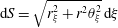 $\text{d}S=\sqrt{r_{\unicode[STIX]{x1D709}}^{2}+r^{2}\unicode[STIX]{x1D703}_{\unicode[STIX]{x1D709}}^{2}}\,\text{d}\unicode[STIX]{x1D709}$
in terms of the Lagrangian variable
 $\unicode[STIX]{x1D709}$
. On the opposite end of the flow domain, i.e. the far field, the imposed pressure disturbance is prescribed on the right-hand side of the radial component of the momentum balance. This is a superparametric interpolation scheme for capturing the position of the interface that has also been used elsewhere in the context of free surface problems (Saito & Scriven Reference Saito and Scriven1981; Kistler & Scriven Reference Kistler, Scriven, Pearson and Richardson1983). Details pertaining to the efficiency of
 $B$
-cubic splines as basis functions in flow problems involving free surfaces are provided in Pelekasis, Tsamopoulos & Manolis (Reference Pelekasis, Tsamopoulos and Manolis1992).
For the grid construction we use and compare two different methods: the spine method and the elliptic mesh generation technique. Both of them are described in detail in appendix B.
The nonlinearity of the problem is treated with the Newton–Raphson method and the following linear system of equations is solved during each iteration:
 $$\begin{eqnarray}\unicode[STIX]{x1D645}\boldsymbol{\cdot }\,\text{d}\boldsymbol{C}=\boldsymbol{R},\end{eqnarray}$$
with
 $\boldsymbol{R}$
denoting the residual vector,
 $\text{d}\boldsymbol{C}$
the vector of the unknowns and
 $\unicode[STIX]{x1D645}$
the Jacobian matrix of the system. Vector
 $\text{d}\boldsymbol{C}$
includes the two components of the velocity and the pressure of the liquid, the gas pressure and the shape of the bubble. The Jacobian matrix,
 $\unicode[STIX]{x1D645}$
, contains the finite element discretization of the momentum and continuity equations (3.1), (3.2), where the fully implicit Euler time integration scheme is implemented, along with the tangential and normal force balances at the interface, equations (3.4), and the isothermal law for the pressure variation in the bubble, equation (2.17). In this fashion, the Jacobian matrix assumes the form of an arrow with the gas pressure and the bubble shape occupying the arrow columns. A separate Newton–Raphson iterative procedure follows the above time integration process within each time step, for the implementation of the elliptic mesh generation scheme and the construction of the updated grid. Despite the fact that in previous numerical studies of the nonlinear dynamic response of liquid drops and bridges (Chen & Tsamopoulos Reference Chen and Tsamopoulos1993; Patzek et al.
Reference Patzek, Basaran, Benner and Scriven1995; Notz & Basaran Reference Notz and Basaran1999, Reference Notz and Basaran2004) the trapezoid rule is implemented in the context of a predictor–corrector time integration scheme, in the present study we employ the fully implicit Euler method in order to make use of its inherent damping properties against growth of spurious shape modes. This approach by no means compromised the accuracy of the solution, as was verified by extensive tests with varying time step and continuous monitoring of the energy.
In order to reduce computational time we have chosen to solve the problem iteratively with the GMRES (Generalized Minimum Residual) (Saad & Schultz Reference Saad and Schultz1986) rather than a direct method. GMRES is an iterative method and therefore is more effective when the matrix to be inverted does not contain zero diagonal elements (Elman, Silvester & Wathen Reference Elman, Silvester and Wathen2005). In the problems examined herein this approach does not apply, and consequently the GMRES method with right or left preconditioning is employed. The preconditioning is performed using Incomplete Lower Upper (ILU) factorization. ILU is based on Gauss elimination in order to eliminate certain elements of the matrix in specific positions outside the main diagonal (Saad Reference Saad1996). The implementation of ILU and GMRES is performed using the SPARSKIT software (Saad Reference Saad1996). It is the experience of the authors that the use of GMRES reduces computational time dramatically, and indeed that was seen to be the case in the present study as well. As an extra effort to further reduce computational time we avoid construction and ILU factorization of the Jacobian matrix in every time step. The number of time steps over which the Jacobian matrix can remain unaltered without compromising the efficiency of the algorithm depends strongly on the intensity of the shape deformation of the bubble, and was seen to vary considerably between 1 and 500 time steps.
3.1 Benchmarks tests
In order to verify the reliability of our methodology we have performed several tests, a few of which are presented in this subsection. As a first numerical test we perform simulations that involve jet formation of gas-filled bubbles. These simulations are based on a previous study (Tsiglifis & Pelekasis Reference Tsiglifis and Pelekasis2007) that takes into account the weak viscous effects of the boundary layer close to the bubble. In that study, Tsiglifis and Pelekasis used elongation to produce an initial asymmetry in the flow domain, and considered an initial internal overpressure:
 $$\begin{eqnarray}P_{G}(t=0)=(P_{st}+1)(1+\unicode[STIX]{x1D700}_{B}),\end{eqnarray}$$
where
 $\unicode[STIX]{x1D700}_{B}$
denotes the amplitude of the internal overpressure; in the latter study pressure is made dimensionless via
 $2\unicode[STIX]{x1D70E}/R_{0}$
. They found that for a slightly elongated bubble,
 $S=0.99$
, and an internal overpressure of
 $\unicode[STIX]{x1D700}_{B}=2$
the bubble collapses when the viscosity of the surrounding liquid is half the viscosity of water;
 $S$
is a parameter introduced in Tsiglifis & Pelekasis (Reference Tsiglifis and Pelekasis2007) that signifies the intensity of the initial elongation, and is associated with the initial shape of the bubble as follows:
 $$\begin{eqnarray}r=f(\unicode[STIX]{x1D703},t=0)=\frac{S}{\sqrt{S^{6}\cos ^{2}\unicode[STIX]{x1D703}+\sin ^{2}\unicode[STIX]{x1D703}}}.\end{eqnarray}$$
When
 $S=1$
the spherical shape is recovered, whereas as
 $S$
decreases the imposed elongation among the axis of symmetry intensifies. Surface tension,
 $\unicode[STIX]{x1D70E}$
, is set to
 $0.0715~\text{N}~\text{m}^{-1}$
and viscosity
 $\unicode[STIX]{x1D707}$
to
 $5\times 10^{-4}~\text{Pa}~\text{s}$
;
 $S$
,
 $\unicode[STIX]{x1D700}_{B}$
and
 $Oh\equiv \unicode[STIX]{x1D707}/(\unicode[STIX]{x1D70C}R_{0}\unicode[STIX]{x1D70E})^{1/2}$
are the relevant dimensionless parameters in that study. It was thus shown that under such conditions the amplitude of the
 $\text{P}_{2}$
Legendre mode of the bubble shape becomes large enough during bubble compression so that two counter-propagating jets are formed along the axis of symmetry which eventually coalesce on the equatorial plane. In particular, the time and space scalings during the final stages of coalescence evolve in the manner prescribed for capillary drop pinch-off. Our simulation for this set of parameters is shown in figure 2, which has been obtained with both spine and elliptic mesh generation techniques providing the same dynamic response. We observe that even though the poles of the bubble move towards each other at some point, i.e. dimensionless time
 $t\approx 54.15$
on a time scale determined by the angular eigenfrequency for volume pulsations
 $\unicode[STIX]{x1D714}_{0}\approx 0.6~\text{MHz}$
, liquid viscosity imposes its stabilizing effect that restricts further growth of the
 $\text{P}_{2}$
mode. Eventually, shape oscillations die-out and the bubble retracts to achieve a static spherical shape. For better visualization all through this paper the shape of the bubble is presented in local Cartesian coordinates,
 $x=r\cos \unicode[STIX]{x1D703}$
and
 $y=r\sin \unicode[STIX]{x1D703}$
, that are defined on the meridional plane.
(a), (b) Temporal evolution of the shape of a gas bubble. (c) Temporal evolution of the average bubble radius via the breathing mode
 $\text{P}_{0}$
, and the most unstable shape Legendre modes,
 $\text{P}_{2}$
and
 $\text{P}_{4}$
. The parameters used in the simulation are taken from Tsiglifis & Pelekasis (Reference Tsiglifis and Pelekasis2007), with
 $Oh=40$
,
 $S=0.99$
and
 $\unicode[STIX]{x1D700}_{B}=2$
.

In order to capture jet formation and bubble collapse we introduce a more intense initial elongation disturbance,
 $S=0.7$
, that viscosity fails to stabilize for the same liquid properties. Figure 3 illustrates the process of bubble deformation and jet formation captured via the spine method with a grid of
 $600\times 160$
elements along the radial and polar directions, respectively, and a time step equal to 0.001. However, and despite the strong indication that the poles of the bubble will coalesce on the equator, the spine method fails to capture the last phase of collapse. This is due to the inability of the spine method to capture extreme and complex deformations. When the grid is constructed elliptically by using
 $300\times 160$
elements we obtain the results shown in figure 4. This simulation was completed in 6 weeks and was performed on a 64 GB Linux machine with an Intel Core i7 CPU at 3.2 GHz. Clearly, the elliptic mesh method is able to follow the intense deformations of the interface and, therefore, to adequately describe the evolution of the phenomenon until its final stages. Liquid viscosity is unable to restrain the growth of the
 $\text{P}_{2}$
mode which occurs in the same manner as reported by Tsiglifis & Pelekasis (Reference Tsiglifis and Pelekasis2007), only for a larger initial elongation than in the latter study owing to the stabilizing effect of the full viscous formulation adopted in the present study. In both cases the amplitude of
 $\text{P}_{2}$
becomes very large during the negative phase of the pulsation, as a result of the large acceleration during the rebound phase of the pulsation, and therefore bubble collapse eventually occurs along the axis of symmetry. Thus, in the latter study, in agreement with previous similar studies by Blake et al. (Reference Blake, Hooton, Robinson and Tong1997, Reference Blake, Keen, Tong and Wilson1999), the final stages of bubble collapse via jet formation are characterized by the onset of a toroidal bubble and a small satellite bubble that occupies the space at the point of impact of the two counter-propagating jets. As will be discussed in the following section, coated microbubbles exhibit a different collapse pattern that does not involve jet formation.
(a) Temporal evolution of bubble shape and (b) temporal evolution of breathing mode
 $\text{P}_{0}$
and shape mode decomposition with the spine method (
 $Oh=40$
,
 $S=0.7$
,
 $\unicode[STIX]{x1D700}_{B}=2$
).

(a) Temporal evolution of bubble shape and (b) temporal evolution of breathing mode
 $\text{P}_{0}$
and shape mode decomposition with the elliptic mesh generation method (
 $Oh=40$
,
 $S=0.7$
,
 $\unicode[STIX]{x1D700}_{B}=2$
).

Figure 5 illustrates the grid that corresponds to the last snapshot of the spine method (figure 3). We present a case with fewer elements
 $(100\times 80)$
for better visualization of the grid and we observe that there is an accumulation of the elements in specific areas. Moreover, the distortion of the elements is so intense that their area becomes negative in certain regions. The regions depicted in black in figure 5 denote such areas. In contrast, figure 6 depicts the grid that corresponds to the last snapshot of the simulation with the elliptic mesh generation technique. In this case the resulting elements are able to follow the large deformation of the interface and, consequently, provide a mesh of better quality. The superiority of the elliptic mesh generation technique against the spine method was a recurring theme in the present study.
Grid obtained for the last snapshot around a gas-filled bubble with the spine method with
 $100\times 80$
elements (
 $\unicode[STIX]{x1D707}=5\times 10^{-4}~\text{P}\unicode[STIX]{x1D6FC}~\text{s}$
,
 $\unicode[STIX]{x1D70E}=0.0715~\text{N}~\text{m}^{-1}$
,
 $S=0.7$
,
 $\unicode[STIX]{x1D700}_{B}=2$
).

Grid obtained for the last snapshot around a gas-filled bubble with the elliptic mesh generation method with
 $300\times 160$
elements and a time step
 $\text{d}t=0.001$
(
 $\unicode[STIX]{x1D707}=5\times 10^{-4}~\text{P}\unicode[STIX]{x1D6FC}~\text{s}$
,
 $\unicode[STIX]{x1D70E}=0.0715~\text{N}~\text{m}^{-1}$
,
 $S=0.7$
,
 $\unicode[STIX]{x1D700}_{B}=2$
).

(a) Temporal evolution of the breathing mode,
 $\text{P}_{0}$
, for a step change disturbance of amplitude
 $\unicode[STIX]{x1D700}=1$
with the spine and the elliptic mesh method. (b) Time variation of the total energy of the bubble/fluid flow system.

Next, we consider the case of an encapsulated bubble with a phospholipid shell, that is subjected to a step change disturbance in the far-field pressure. Indicative values pertaining to soft phospholipid shells are employed, that have previously been used for performing dynamic simulations with the boundary element method (Tsiglifis & Pelekasis Reference Tsiglifis and Pelekasis2013) and have been cross-checked against relevant studies from the literature of contrast agents (Qin & Ferrara Reference Qin and Ferrara2006; Dollet et al.
Reference Dollet, Van der Meer, Garbin, de Jong, Lohse and Versluis2008). The bubble is initially of spherical shape with a radius of
 $R_{0}=3.6~\unicode[STIX]{x03BC}\text{m}$
, and the shell is stress free with viscosity
 $\unicode[STIX]{x1D707}_{s}=60\times 10^{-9}~\text{kg}~\text{s}^{-1}$
, area dilatation modulus
 $\unicode[STIX]{x1D712}=0.24~\text{N}~\text{m}^{-1}$
, bending modulus
 $k_{b}=3\times 10^{-14}~\text{N}~\text{m}$
while obeying the Mooney–Rivlin constitutive law with the degree of softness
 $b$
equal to zero (Barthes-Biesel et al.
Reference Barthes-Biesel, Diaz and Dhenin2002; Tsiglifis & Pelekasis Reference Tsiglifis and Pelekasis2008). The surface tension
 $\unicode[STIX]{x1D70E}$
is set to
 $0.051~\text{N}~\text{m}^{-1}$
, the polytropic ideal gas constant is set to
 $\unicode[STIX]{x1D6FE}=1.07$
, whereas the liquid that surrounds the bubble is assumed to have the properties of water and the far-field pressure is taken to be the standard ambient pressure of 1 atm. According to static analysis the critical threshold in the external pressure disturbance for static buckling to take place is
 $\unicode[STIX]{x1D700}_{cr}=1.35$
for this set of parameters. Above this value the asymmetric mode
 $\text{P}_{3}$
appears, whereas for a step change in pressure greater than 1.43 the symmetric mode
 $\text{P}_{2}$
is observed. Each one of the above events signifies the onset of a bifurcating curve that is seen to initially extend subcritically to smaller external overpressures (Lytra & Pelekasis Reference Lytra and Pelekasis2014). As a first test we impose a step change disturbance of amplitude
 $\unicode[STIX]{x1D700}=1$
which is smaller than the critical buckling threshold reported above. The bubble is observed to perform few volume pulsations (figure 7), due to the relatively high shell viscosity. The oscillations are quickly damped mainly due to shell viscosity, and, eventually, the bubble acquires a compressed spherical state at static equilibrium with a smaller dimensionless radius
 $(R=0.893)$
than the initial. It should also be stressed that the period of oscillation, before static configuration is established, is controlled by the far-field pressure
 $P_{\infty }^{\prime }$
after the step change is imposed, in conjunction with the compressed bubble radius
 $R_{0}$
prescribed by (2.3), as this can be verified by performing a direct comparison with the time series of the internal gas pressure shown in figure 7(a). The static solution persisted in time over an extended duration of the simulation and no shape deformation was obtained, as expected since we operate below the buckling threshold. This is also illustrated in figure 7(b), where the variation of the total energy of the flow system comprising the surrounding liquid and the coated bubble is portrayed until static equilibrium. Both mesh generation techniques produced the same dynamic pattern in this subcritical regime.
Upon gradually increasing the amplitude of the external disturbance the static buckling threshold value of
 $\unicode[STIX]{x1D700}=1.35$
, obtained via linear stability analysis (Tsiglifis & Pelekasis Reference Tsiglifis and Pelekasis2011) and numerical construction of the static bifurcation diagram (Lytra & Pelekasis Reference Lytra and Pelekasis2014), is recovered by the simulations leading to non-spherical asymmetric static configurations, as will be shown in detail in the following sections.
At this point it is crucial to mention that in all simulations presented herein mode
 $\text{P}_{1}$
, denoting translation of the centre of mass, is not enforced to vanish. Rather it is allowed to grow, a process that is naturally expected to take place, in order to facilitate energy distribution among shape modes and relieve extra tension on the deforming shell. This is a rather slow process and arises as a result of nonlinear interaction between consecutive shape modes,
 $\text{P}_{n}$
and
 $\text{P}_{n+1}$
(Doinikov Reference Doinikov2004) that emerge in the process of shell deformation. In fact, whenever the centre of mass of the bubble was forced to remain on the origin of the coordinate system, no static equilibrium was observed. The same numerical issues arise if we ignore viscous effects in the surrounding liquid, by setting liquid viscosity
 $\unicode[STIX]{x1D707}$
in the context of the present simulation to zero, in which case the singular limit of inviscid flow is recovered with a boundary layer of zero thickness. Nevertheless, the limit of negligible viscous dissipation in the liquid viscosity is examined by sufficiently decreasing the value of viscosity
 $\unicode[STIX]{x1D707}$
without setting it to zero. Furthermore, allowing for a certain amount of surface tension, i.e.
 $\unicode[STIX]{x1D70E}=0.051~\text{N}~\text{m}^{-1}$
, has a stabilizing effect on the simulations by decreasing the severity of the initial disturbance via the amount of extra internal pressure it introduces in the stress-free state. Finally, in order to avoid accuracy losses when significant translation of the centre of mass takes place, especially when static equilibrium involves asymmetric shapes, the origin of the coordinate system is moved to the midpoint between the two poles.
Using the numerical methodology presented above, an extensive parametric study was conducted in the next section. In view of the wide spectrum of possible static shapes attained by coated microbubbles, especially for mild deformations, the spine and elliptic mesh generation methods may produce different static equilibria, which, however, were all shown to be numerically converged and valid entries corresponding to different solution families in the bifurcation diagram. The elliptic mesh generation technique was able to reproduce all the shapes calculated via the spine method, but it was also seen to perform much better than the spine method in capturing severely deformed shapes, some of which, as was illustrated in figure 5, are not accessible via the spine method. However, wherever possible, the latter method was employed in view of the less intensive computational effort it entails. It should also be stressed that a detailed presentation of the structure of the bifurcation diagrams corresponding to the shell parameters that were investigated was not pursued herein, in the interest of space and clarity, and a more comprehensive investigation is left for a future study.
4 Results and discussion
In this section we present an extensive parametric study in our effort to capture the dynamics of coated microbubbles in response to a step change in the far-field pressure, until static equilibrium is achieved. Previous static and stability analysis for both polymeric and the softer phospholipid shells (Tsiglifis & Pelekasis Reference Tsiglifis and Pelekasis2011; Lytra & Pelekasis Reference Lytra and Pelekasis2014) predict the onset of a bifurcating branch that is characterized by symmetric or asymmetric shapes when static buckling first occurs, depending on the area dilatation modulus,
 $\unicode[STIX]{x1D712}$
, of the shell. In particular, for relatively smaller values of the area dilatation modulus, static buckling favours asymmetric shapes that are indented in one of the two poles where bending stresses develop in an effort to relieve the shell from the excess energy due to compressive stresses. In contrast, as it increases, symmetric shapes emerge in the post-buckling state where a local indentation at both poles arises. Such a static arrangement facilitates the development of bending stresses in a larger portion of the shell, as a means to alleviate the intense straining of compressed spherical shells characterized by a large area dilatation modulus. This pattern is particularly true for phospholipid shells (they are the focus of the present study) that obey the Mooney–Rivlin constitutive law and become even harder at compression. The crucial parameter that determines the onset of buckling is the stiffness ratio between bending and dilatation,
 $k_{b}/(\unicode[STIX]{x1D712}R_{0}^{2})=(\unicode[STIX]{x1D6FF}/3/R_{0})^{2}$
when
 $\unicode[STIX]{x1D708}=0.5$
, with
 $\unicode[STIX]{x1D6FF}$
denoting the shell thickness and
 $\unicode[STIX]{x1D708}$
the Poisson ratio. Furthermore, the resistance to compression is an additional factor that affects the static and dynamic response of phospholipid shells, in comparison with the hard polymeric ones, as will be seen from the analysis of the results that follows based on the relative volume compression to area dilatation stiffness,
 $P_{St}R_{0}/\unicode[STIX]{x1D712}$
. The dynamic pattern towards the static equilibrium is of interest as a function of the shell parameters in the presence of viscous dissipation in the surrounding liquid, in view of the fact that static equilibrium was not captured in the context of boundary element dynamic simulations presented in Tsiglifis & Pelekasis (Reference Tsiglifis and Pelekasis2013). In particular, we are interested in investigating the possibility that the above static shapes be anticipated by finite time singularities that are typically observed with gas bubbles such as jet formation and breakup.
The phospholipid shell that was studied in the benchmark calculation presented in the previous section is simulated, setting the area dilatation modulus and imposing a series of step change disturbances, in order to study the dynamic evolution of the shell shape towards static equilibrium. For this particular set of parameters, setting area dilatation modulus
 $\unicode[STIX]{x1D712}$
to
 $0.12~\text{N}~\text{m}^{-1}$
, static stability analysis records two non-spherical bifurcating branches, off the main branch of compressed spherical shells, dominated by symmetric and asymmetric
 $\text{P}_{2}$
and
 $\text{P}_{3}$
modes, respectively. The first one emerges at the critical value of
 $\unicode[STIX]{x1D700}=1.65$
, whereas the critical threshold for the asymmetric branch is
 $\unicode[STIX]{x1D700}=1.78$
(Lytra & Pelekasis Reference Lytra and Pelekasis2014). Our dynamic simulations verify that the threshold in step change for static buckling to occur is 1.65. Moreover, as was also reported in § 3.1 that was dedicated to benchmarking, below this threshold it was not possible to capture any deformed shapes at static equilibrium irrespective of the initial shape disturbance that was applied on the compressed spherical shape obtained for a certain step change in pressure. In particular, the eigenvector obtained at criticality was superimposed on the compressed spherical shape in the form of an initial shape imperfection with increasing amplitude,
 $r=R+\unicode[STIX]{x1D700}F(\unicode[STIX]{x1D709})$
.
 $F(\unicode[STIX]{x1D709})$
denotes the eigenvector corresponding to the eigenvalue that first turns unstable at criticality (see also Lytra & Pelekasis (Reference Lytra and Pelekasis2014)), and contains all the characteristics of the solution family that bifurcates from the main spherical branch at the buckling threshold. In all cases the shell eventually returned to the spherical configuration, thus verifying the subcritical nature of the bifurcation. In contrast, when the initial step change in pressure exceeded the critical buckling threshold value, the coated bubble was seen to eventually reach a non-spherical static equilibrium, even in the absence of an initial shape disturbance.
This behaviour is in marked contrast with the dynamic response of polymeric shells in the neighbourhood of the bifurcation point (figure 5 in Tsiglifis & Pelekasis (Reference Tsiglifis and Pelekasis2013)). In the latter case static stability predicts that an asymmetric eigenmode,
 $\text{P}_{11}$
, dominates the post-buckling behaviour, followed by a symmetric bifurcation characterized by
 $\text{P}_{12}$
. Nevertheless, dynamic simulations with the boundary integral method as well as with the present finite element methodology do not recover the spherical shape or the primary bifurcation branch for perturbations below or above the bifurcation point, respectively. Rather they indicate a continuous evolution of the shape that is conjectured to lead to breakup or to the formation of contact regions. In the present study it will be seen that phospholipid shells exhibit a different response pattern leading to deformed shapes of different intensity depending on the magnitude of the step change in the far-field pressure. As the latter is further increased, static shapes exhibiting contact are captured by the dynamic simulations rather than jet formation or breakup.
(a) Temporal evolution of bubble shape and (b) temporal evolution of radius and shape mode decomposition for a contrast agent (
 $R=3.6~\unicode[STIX]{x03BC}\text{m}$
,
 $\unicode[STIX]{x1D707}_{s}=20~\text{Pa}~\text{s}$
,
 $\text{thickness}=1~\text{nm}$
,
 $\unicode[STIX]{x1D712}=0.12~\text{N}~\text{m}^{-1}$
,
 $k_{b}=3\times 10^{-14}~\text{N}~\text{m}$
) for a step change disturbance (
 $\unicode[STIX]{x1D700}=2$
) with the spine method. (c) Total energy variation, (d) viscous versus shell damping and (e) distribution among different forms of energy as a function of time.

(a) Temporal evolution of bubble shape and (b) temporal evolution of radius and shape mode decomposition for a contrast agent (
 $R=3.6~\unicode[STIX]{x03BC}\text{m}$
,
 $\unicode[STIX]{x1D707}_{s}=20~\text{Pa}~\text{s}$
,
 $\text{thickness}=1~\text{nm}$
,
 $\unicode[STIX]{x1D712}=0.12~\text{N}~\text{m}^{-1}$
,
 $k_{b}=3\times 10^{-14}~\text{N}~\text{m}$
) for a step change disturbance (
 $\unicode[STIX]{x1D700}=2$
) with the elliptic mesh method. (c) Total energy variation, (d) viscous versus shell damping and (e) distribution among different forms of energy as a function of time.

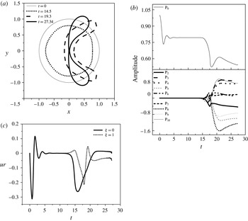
Figures 8 and 9 illustrate the rich bifurcation structure that is produced in the post-buckling, or supercritical, regime in terms of the amplitude
 $\unicode[STIX]{x1D700}$
of the step change in the far-field pressure. In both cases
 $\unicode[STIX]{x1D700}$
is set to 2, which is above the buckling threshold, with the spine and elliptic mesh generation procedures implemented in figures 8 and 9, respectively. Both are valid and numerically converged static equilibrium shapes, and represent possible alternative static configurations to the spherical shape for the same external overpressure. The shape evolution of the coated bubble until static equilibrium is established is shown in figure 8(a), captured via the spine method, indicating the onset of a symmetric oblate static shape that exhibits indentations in an extended region around the two poles. As a result of the strain-softening nature of the Mooney–Rivlin shell it becomes harder at compression, and consequently an indentation starts to develop in the pole region as a means to relieve the shell from the large in-plane stresses, via bending. This can be gleaned from figure 8(b), illustrating the Legendre mode decomposition of the bubble shape. The breathing mode
 $\text{P}_{0}$
in particular exhibits a first plateau, after a short oscillatory phase with its natural angular frequency
 $\unicode[STIX]{x1D714}_{0}$
, corresponding to the compressed spherical shape in response to the step change in pressure
 $(R=0.8022)$
. Subsequently buckling takes place, and energy is distributed among different shape modes until the shell settles to a symmetrically deformed state dominated by
 $\text{P}_{2}$
and
 $\text{P}_{4}$
in figure 8(b).
It should be stressed that, during the transient phase between the compressed spherical state and the final static shape, asymmetric modes emerge, most notably
 $\text{P}_{3}$
as can be gleaned from the mode decomposition shown in figure 8(b) and the corresponding shapes in figure 8(a), indicating the possibility for asymmetrically deformed static shapes to develop. Indeed, asymmetric static shapes are also possible for the same parameter values. Nevertheless, the symmetric configuration prevails at static equilibrium owing to its comparatively smaller total energy, as shown in figure 8(c), depicting the evolution of the total shell energy. The energy variation follows a similar pattern as the breathing mode
 $\text{P}_{0}$
with the initially elevated energy content, attributed to surface energy and internal/external pressure level, gradually dissipated predominantly by the action of shell viscosity; see also figure 8(d), presenting the shell and liquid components of viscous dissipation during the entire process. In this fashion, the shell goes through a local energy minimum corresponding to a compressed sphere, which is further destabilized to acquire the final symmetric shape with the slight indentation at the two poles. At this point it should be stressed that, despite the fact that based on static analysis (Lytra & Pelekasis Reference Lytra and Pelekasis2014) the spherical shape was found to be favoured energetically over all deformed shapes in the post-buckling regime, simulations performed herein show that, when the surrounding liquid is included in the total energy balance, deformed shapes that exhibit significant volume compression (
 $V/V_{0}=0.47$
versus 0.516 for the compressed sphere) at static equilibrium acquire lower energy levels than the equivalent spherical ones obtained for the same step change in the external pressure, and as a result dominate static equilibrium. This is clearly illustrated in figure 8(c) and is a recurring theme in the present study. The decomposition of energy among various forms is shown in figure 8(e), where the importance of bending and surface energy in redistributing the shell energy due to stretching and compression, thus leading to energy minimum, is illustrated.
Figure 9(a) depicts the dynamic pattern of shape deformation of a microbubble subject to the same disturbance as in figure 8, as obtained with the elliptic mesh generation technique. The response pattern is similar with the difference that now prolate shapes are obtained at static equilibrium. This is an equally valid and numerically converged static solution belonging to a different bifurcation branch that is achieved instead of the oblate shapes as a result of the different numerical attributes of the elliptic mesh generation scheme. This is verified independently from the above dynamic simulations in the context of static analysis and is a manifestation of the rich bifurcation diagram of coated microbubbles. As in figure 8, an intermediate spherical state is obtained with the shell being uniformly compressed, in figure 9(b), that is further destabilized in order to release the excess elastic energy it has acquired as a result of shell hardening during compression, by redistributing it along the interface or by converting it to bending energy. In this simulation it is also the case that the second Legendre mode dominates, with
 $\text{P}_{3}$
and the rest of the asymmetric modes remaining negligibly small while
 $\text{P}_{4}$
and the rest of the symmetric modes gradually grow due to nonlinearity (figure 9
b). Eventually a symmetrically deformed static shape emerges that is prolate along the axis of symmetry. This shape is also characterized by more severe volume compression,
 $V/V_{0}=0.51$
versus 0.516 for the spherical shape, and consequently smaller energy content than the uniformly compressed shell (figure 9
c). This static equilibrium shape constitutes an alternative arrangement at static equilibrium, for the same parameter range, that is a result of the additional degrees of freedom offered by shell elasticity to the microbubble’s dynamics. Throughout the above-described dynamic process, energy is dissipated mainly due to shell viscosity that dominates liquid viscosity (figure 9
d), especially during compression. The prolate shape obtained in this case does not exhibit significant bending (figure 9
a,e), owing to the relatively large bending stiffness,
 $k_{b}/(\unicode[STIX]{x1D712}R_{0}^{2})\approx 0.02$
, and hence the lack of indentations. Bending of the shell at the equator is not as effective in reducing shell energy since it basically affects in-plane stresses in the polar direction, whereas bending around the poles uniformly affects in-plane stresses along both the polar and azimuthal directions. Hence, among the two symmetric static configurations, the one with the oblate shape is more stable in the sense that its energy content is lower. It should also be stressed that the pattern of prolate versus oblate shapes was not seen in static calculations of coated bubbles obtained in previous studies (Knoche & Kierfeld Reference Knoche and Kierfeld2011; Lytra & Pelekasis Reference Lytra and Pelekasis2014). This is attributed to the relatively larger value of the relative stiffness ratio,
 $k_{b}/(\unicode[STIX]{x1D712}R_{0}^{2})\approx 0.02$
for the parameter range relevant to the simulations shown in figures 8 and 9, that makes bending an energy consuming alternative to stretching, thus affording the onset of stable prolate shapes in the post-buckling regime.
Upon increasing the amplitude of the external disturbance
 $(\unicode[STIX]{x1D700}=3)$
the spine method fails to capture the evolution of the interface. In contrast, the elliptic mesh generation technique (figure 10), captures the time evolution of the dynamic response until static equilibrium. The final static shape is a symmetric oblate one with two indentations in the region around the two poles. It is essentially a continuation of the static arrangement produced by the spine method when
 $\unicode[STIX]{x1D700}=2$
(see also figure 8), that proceeds further along the bifurcation branch pertaining to oblate shapes. It constitutes the preferred static arrangement owing to its lower energy content in comparison with the prolate shapes.
(a) Temporal evolution of bubble shape and (b) temporal evolution of shape mode decomposition for a contrast agent (
 $R=3.6~\unicode[STIX]{x03BC}\text{m}$
,
 $\unicode[STIX]{x1D707}_{s}=20~\text{Pa}~\text{s}$
,
 $\text{thickness}=1~\text{nm}$
,
 $\unicode[STIX]{x1D712}=0.12~\text{N}~\text{m}^{-1}$
,
 $k_{b}=3\times 10^{-14}~\text{N}~\text{m}$
) for a step change disturbance
 $(\unicode[STIX]{x1D700}=3)$
with the elliptic mesh method. (c) Grid generated via the elliptic mesh generation technique. (d) Total energy variation and (e) distribution among different forms of energy as a function of time. (f) Time evolution of
 $\text{P}_{1}$
and (g) time evolution of shape mode decomposition when the origin of the coordinate system is moved.

The shape and mode decomposition in this case are provided in figure 10(a,b). Figure 10(c) depicts the computational grid produced by the elliptic mesh generation technique as the indentation around the two poles develops. The increased area of the elements near the two indentations is evident, indicating the relatively larger error in these two areas. The fashion in which static equilibrium is approached should also be noted, as the shell temporarily acquires asymmetric shapes dominated by
 $\text{P}_{3}$
and
 $\text{P}_{5}$
, marking the existence of an additional asymmetric branch with a single indentation at the north pole; see also the time evolution of the microbubble shapes shown in figure 8(a), obtained with the spine method when
 $\unicode[STIX]{x1D700}=2$
. Nevertheless, here also the oblate symmetric shape eventually prevails due to its lower energy content (figure 10
d). The pattern of shell damping dissipating the kinetic energy by relaxing the compressive stresses persists in this case also (figure 10
e). Eventually, the shell acquires its static arrangement with bending stresses developing at the expense of strain.
Another important aspect of this simulation pertains to the gradual emergence of a translational motion of the microbubble’s centre of mass that can also be observed by careful inspection of figure 10(a). This is a result of nonlinear interaction between emerging consecutive shape modes,
 $\text{P}_{n}$
and
 $\text{P}_{n+1}$
, that can also explain the persistence of
 $\text{P}_{3}$
and
 $\text{P}_{5}$
in the symmetric static shape whose centre of mass is clearly displaced from its original position at the origin of the coordinate system. The displacement is more severe in comparison with the situation shown in figure 8(a) due to the smaller initial disturbance in the latter case (see also figure 10(f) illustrating the time evolution of
 $\text{P}_{1}$
). Upon moving the origin of the coordinate system to the midpoint between the two poles (figure 10
g), the same symmetric static shape is obtained while the odd modes are removed from the Legendre decomposition of the shape.
As the intensity of the step change is further increased, setting
 $\unicode[STIX]{x1D700}=3.5$
, the solution family of oblate shapes persists as the preferred static configuration, with the emerging shape exhibiting a contact region where the two poles meet (figure 11
a). The mode decomposition of the shell shape becomes richer in higher modes (figure 11
b), while the total energy never fully settles to a constant value (figure 11
c). In fact, as illustrated in figure 11(d), showing the evolution of the normal velocity at the north pole, the latter acquires a large speed as the indentation forms and gradually intensifies. This is a manifestation of the divergence process that takes place during the buckling event. However, the process of kinetic energy accumulation is eventually arrested mainly by the development of viscous stresses in the shell that mitigate the onset of compressive in-plane stresses. The kinetic energy of the shell as well as the energy due to compression and strain are redistributed in favour of bending and surface energy; see also figure 11(e). For large external overpressures, prolonged action of shell viscosity significantly relaxes the compressive stresses in the pole region where the indentation arises. In this process the pole region assumes an almost spherical shape as the radius of curvature progressively decreases following the volume change; see also figure 11(c–f), while bending takes place mostly around the equator.
(a) Temporal evolution of bubble shape and (b) temporal evolution of shape mode decomposition for a contrast agent (
 $R=3.6~\unicode[STIX]{x03BC}\text{m}$
,
 $\unicode[STIX]{x1D707}_{s}=20~\text{Pa}~\text{s}$
,
 $\text{thickness}=1~\text{nm}$
,
 $\unicode[STIX]{x1D712}=0.12~\text{N}~\text{m}^{-1}$
,
 $k_{b}=3\times 10^{-14}~\text{N}~\text{m}$
) for a step change disturbance
 $(\unicode[STIX]{x1D700}=3.5)$
with the elliptic mesh method. (c) Time evolution of the total shell energy. (d) Temporal evolution of velocity at the two poles. (e) Distribution among different forms of energy and (f) viscous versus shell damping as a function of time.

Eventually contact is established in the region around the two poles, while the shell never quite achieves a static configuration, since simulations cannot proceed beyond the point of first contact. To this end, further modelling is required and is out of the scope of the present study. Rather, this is viewed as the inception of the dynamic process leading to the formation of a contact region. Thus, it is anticipated that the eventual static equilibrium will exhibit regions of contact whose length depends on the magnitude of the external overpressure, in the manner that earlier studies of the static response of hard shells (Knoche & Kierfeld Reference Knoche and Kierfeld2011) obtain shapes with progressively longer contact regions at the poles as the limiting state of solution families with post-buckling shapes. In this fashion, jet formation is avoided as it entails the onset of areas of very large curvature and speed corresponding to large bending and kinetic energy components. This is, however, prevented by the action of shell viscosity that damps kinetic energy and does not allow intensive bending or strain to develop in the pole region.
(a) Temporal evolution of bubble shape and (b) temporal evolution of radius and shape mode decomposition for a contrast agent (
 $R=3.6~\unicode[STIX]{x03BC}\text{m}$
,
 $\unicode[STIX]{x1D707}_{s}=20~\text{Pa}~\text{s}$
,
 $\text{thickness}=1~\text{nm}$
,
 $\unicode[STIX]{x1D712}=0.24~\text{N}~\text{m}$
,
 $k_{b}=3\times 10^{-14}~\text{N}~\text{m}$
) for a step change disturbance (
 $\unicode[STIX]{x1D700}=2$
) with the elliptic mesh method. (c) Time evolution of the total shell energy. (d) Viscous versus shell viscosity and (e) distribution among different forms of energy as a function of time.

Next we examine a case where, according to static analysis (Tsiglifis & Pelekasis Reference Tsiglifis and Pelekasis2013; Lytra & Pelekasis Reference Lytra and Pelekasis2014), a bifurcation to an asymmetric static state emerges first in the original branch pertaining to isotropically compressed spherical shells. To this end we consider the same contrast agent as in the previous paragraphs with twice the area dilatation modulus
 $(\unicode[STIX]{x1D712}=0.24~\text{N}~\text{m}^{-1})$
. This microbubble is characterized by a smaller bending to stretching stiffness ratio,
 $k_{b}/(\unicode[STIX]{x1D712}R_{0}^{2})\approx 0.01,$
and an
 $O(1)$
volume compression to area dilatation stiffness ratio,
 $P_{St}R_{0}/\unicode[STIX]{x1D712}\approx 1.5$
. Based on static stability the buckling threshold for such a shell corresponds to a disturbance with amplitude
 $\unicode[STIX]{x1D700}=1.35$
and signifies the onset of an asymmetric mode, namely
 $\text{P}_{3}$
. As the amplitude is further increased to
 $\unicode[STIX]{x1D700}=1.43$
, a second bifurcation occurs that is dominated by the symmetric mode
 $\text{P}_{2}$
. Figure 12 provides the response pattern of a microbubble of this size and shell type to a step change disturbance with amplitude
 $\unicode[STIX]{x1D700}=2$
as obtained via the elliptic mesh generation technique. After the standard plateau corresponding to the compressed spherical shape the symmetric Legendre mode
 $\text{P}_{4}$
appears first, followed shortly by modes
 $\text{P}_{3}$
and
 $\text{P}_{2}$
. Subsequently, more modes appear as a result of nonlinear interaction. It is of great interest that shortly after the onset of static buckling the bubble temporarily (dimensionless time
 $t\approx 88.4$
) achieves static equilibrium with an oblate symmetric shape that is bent in the region around the two poles (figure 12
a). Figure 12(b) illustrates mode saturation for the period between
 $t=75$
and
 $t=90$
corresponding to the above oblate static shape, after the onset of the unstable spherical static shape during the time interval
 $10<t<65$
. The latter is an acceptable static configuration belonging to another solution family of the bifurcation diagram of the coated microbubble under examination. As time evolves, due to numerical disturbances, the latter static shape is also destabilized and the bubble, eventually, reaches another deformed static state that is asymmetric and is characterized by significant volume reduction and lower total energy content compared to the intermediate symmetric one (figure 12
c). The extent of energy dissipation is plotted in figure 12(d), where the dominant effect of shell viscosity is illustrated. It should also be pointed out that owing to the relatively large resistance to area dilatation, smaller bending to stretching stiffness ratio with respect to the case shown in figure 9, an indentation arises in the region around one of the two poles in order to reduce the energy of the system, thus leading to the asymmetric static arrangement. Furthermore, volume compression takes place as an additional means to relieve excessive in-plane stresses. The above energy redistribution process is captured in figure 12(e), where the increase of bending and compression energy over stretching is illustrated.
The onset of static shapes with significant deformation and volume reduction that are energetically favoured over the spherical configuration is a characteristic feature of lipid shells, for which resistance to compression constitutes a major stiffness component, that was systematically captured in the present study over the entire range of parameters that was investigated. This is an important aspect of the dynamic response of microbubbles coated with lipid shells, that is conjectured to be of central importance in the interpretation of acoustic response of such microbubbles that exhibit a strong preference towards compression as this is manifested in the compression-only behaviour. Furthermore, it will be important to assess the impact of such a shape transition in the estimation of elastic properties of the shell via acoustic measurements.
(a) Temporal evolution of velocity at the two poles, (b) spatial distribution of shell and viscous stresses at
 $t=67.5$
and (c) spatial distribution of shell and viscous stresses at
 $t=107$
for a contrast agent (
 $R=3.6~\unicode[STIX]{x03BC}\text{m}$
,
 $\unicode[STIX]{x1D707}_{s}=20~\text{Pa}~\text{s}$
,
 $\text{thickness}=1~\text{nm}$
,
 $\unicode[STIX]{x1D712}=0.24~\text{N}~\text{m}$
,
 $k_{b}=3\times 10^{-14}~\text{N}~\text{m}$
) for a step change disturbance (
 $\unicode[STIX]{x1D700}=2$
) with the elliptic mesh method.

Figure 13(a) provides the temporal evolution of the radial velocity of the two poles for the entire duration of the simulation. It is clear that during a certain time interval
 $(t\approx 55)$
, pertaining to the onset of a symmetric static equilibrium, both poles of the bubble start moving inwards with an increasing velocity. The greater velocity, in absolute value, is observed when the shape in the region around the two poles is flattened
 $(t\approx 67.5)$
and before bending takes place, indicating the onset of divergence. Beyond this time range, the motion of the poles is decelerated due to the combined action of shell viscosity and elasticity as well as, to a lesser extent, viscous dissipation due to shear on the liquid side; see also figure 13(b,c) pertaining to symmetric and asymmetric shapes, respectively. In these graphs
 $\unicode[STIX]{x1D70F}_{s,el}$
and
 $\unicode[STIX]{x1D70F}_{\unicode[STIX]{x1D711},el}$
denote the elastic shell stresses and
 $\unicode[STIX]{x1D70F}_{s,v}$
and
 $\unicode[STIX]{x1D70F}_{\unicode[STIX]{x1D711},v}$
are the viscous shell stresses, while
 $\unicode[STIX]{x1D70F}_{,rr}\unicode[STIX]{x1D70F}_{,r\unicode[STIX]{x1D703}}\unicode[STIX]{x1D70F}_{,\unicode[STIX]{x1D703}\unicode[STIX]{x1D703}}$
and
 $\unicode[STIX]{x1D70F}_{,\unicode[STIX]{x1D711}\unicode[STIX]{x1D711}}$
signify the liquid stresses on the interface; figure 13(b,c) illustrates their impact in the regions around the two poles,
 $m_{s}$
,
 $m_{f}$
denote the bending moments in
 $s$
and
 $\unicode[STIX]{x1D711}$
directions, respectively. The latter quantities are almost the same in the two pole regions, indicating a negligible transverse shear
 $q$
. Eventually, asymmetric modes prevail, leading to the energetically favoured shape of a shell that is bent on one of the two poles only (figure 13
c).

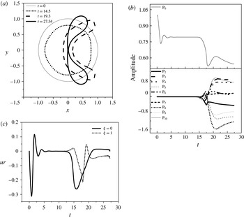
For large enough step changes in the far-field pressure the asymmetric shapes that emerge in the process of achieving static equilibrium are characterized by contact in the pole region as well; see also figure 14(a) obtained for the case with
 $\unicode[STIX]{x1D700}=3$
and
 $\unicode[STIX]{x1D712}=0.24~\text{N}~\text{m}^{-1}$
. This pattern of gradual increase of the asymmetry along this solution family, leading towards crescent-shaped shells and shells with contact at the pole region, was also observed in the static analysis of constant volume and constant pressure hard polymeric shells (Knoche & Kierfeld Reference Knoche and Kierfeld2011), with the exception that in the latter study the relevant asymmetric branch proceeded towards small compression levels as the external overpressure increased. Furthermore, in the latter study a static equilibrium with the opposite sides in contact is energetically favoured by hard shells when they are subjected to overpressures both above and below the buckling threshold. In the present study the strain-softening nature of phospholipid shells generates prohibitively large in-plane stresses at mildly large compression levels, and consequently a combination of bending and compression is enough for static equilibrium to be sustained; see also figure 12(a,b) exhibiting asymmetric shapes before contact regions are established.
As the external overpressure increases, shell viscosity reduces the compressive stresses in the pole region, prevents areas of intense bending or stretching from appearing in the pole region, and consequently jet formation is negated. The pattern captured in figure 11 for symmetric shapes was reproduced by the simulations for a larger initial overpressure (figure 14) when
 $\unicode[STIX]{x1D700}=3$
, that gradually lead to a static arrangement with asymmetric contact regions. In particular, the process of static buckling begins sooner as a result of the larger overpressure and the bubble continues to deform until it collapses with the two poles coalescing along the axis of symmetry. The poles of the bubble start to move inwards after a certain time with an increasing velocity, but soon enough the velocity starts decreasing due to the action of shell viscosity. The difference in the case of figure 14(a) lies in the evolution of curvatures in the regions around the two poles. The north pole,
 $\unicode[STIX]{x1D709}=0$
, exhibits a similar behaviour as in figure 11(a) with progressively smaller bending stresses as the interface retracts to a spherical shape. The south pole acquires an almost flat shape as it approaches static equilibrium, it takes longer to decelerate and coalesces with the north pole as it moves in the same direction but with a larger speed, before the microbubble settles down to a full static equilibrium. Nevertheless, there is no tendency for jet formation as the speed of the interface gradually vanishes, and the tendency for static equilibrium to be achieved is illustrated. Clearly, a significantly larger numerical effort is required in order to capture the point of contact with greater accuracy, and this was not pursued in the present study.
The above process, that leads to the establishment of shapes with contact, was a recurring theme in this study and is in marked contrast with the collapse process via jet formation that is typical for conventional bubbles. The latter type of bubbles exhibit jet formation even in the absence of a nearby wall (Dear & Field Reference Dear and Field1988), provided a large enough initial excitation is applied for fixed viscosity of the surrounding liquid. As was illustrated by the simulations performed in the present study, this is not the case with coated microbubbles, which exhibit a different type of finite time singularity during the ‘collapse’ process, that does not involve jet formation or formation of toroidal and satellite bubbles. Instead of pinching and the onset of areas of very large curvature at the points of contact, the regions of contact that are established around the two poles of coated microbubbles, provided the initial pressure disturbance is large enough, are characterized by finite curvature, small strain and significantly reduced speed under the combined action of shell viscosity and elasticity in the manner described in the above paragraphs. This process is conjectured to lead to the formation of almost flat contact regions in the vicinity of the two poles, such as often captured under static loading of shells.
Further increase of the area dilatation modulus
 $\unicode[STIX]{x1D712}$
to 0.96 further decreases the bending to stretching,
 $k_{b}/(\unicode[STIX]{x1D712}R_{0}^{2})\approx 0.0025,$
and volume compression to area dilatation,
 $P_{St}R_{0}/\unicode[STIX]{x1D712}\approx 0.375,$
stiffness ratios, thus favouring bending and volume compression in the post-buckling regime. Indeed, as illustrated in figure 15(a), obtained for an external overpressure with
 $\unicode[STIX]{x1D700}$
set to 1.3, the time evolution of the microbubble towards a static arrangement is dominated by
 $\text{P}_{4}$
(figure 15
b), and is symmetric with multiple bending regions and significant volume compression. This static shape corresponds to a different solution family than the prolate/oblate and asymmetric ones examined thus far, that also evolves to exhibit contact regions at larger external overpressures. In fact, upon increasing the external overpressure to 2, the pattern towards a static configuration with contact regions is recovered (figure 16
a), with the kinetic energy gradually dissipated in favour of bending and volume compression (figure 16
d). As a result of the prolonged action of shell viscosity (figure 16
e), growth of bending stresses is arrested in the region around the two poles and is restricted to the equator region. The former region acquires an almost spherical shape in the manner previously described for symmetric shapes in figure 11; see also the stress distribution along the shell provided in figure 16(f).
(a) Temporal evolution of bubble shape and (b) temporal evolution of shape mode decomposition for a contrast agent (
 $R=3.6~\unicode[STIX]{x03BC}\text{m}$
,
 $\unicode[STIX]{x1D707}_{s}=20~\text{Pa}~\text{s}$
,
 $\text{thickness}=1~\text{nm}$
,
 $\unicode[STIX]{x1D712}=0.96~\text{N}~\text{m}^{-1}$
,
 $k_{b}=3\times 10^{-14}~\text{N}~\text{m}$
) for a step change disturbance with
 $\unicode[STIX]{x1D700}=1.3$
.

(a) Temporal evolution of bubble shape (
 $R=3.6~\unicode[STIX]{x03BC}\text{m}$
,
 $\unicode[STIX]{x1D707}_{s}=20~\text{Pa}~\text{s}$
,
 $\text{thickness}=1~\text{nm}$
,
 $\unicode[STIX]{x1D712}=0.96~\text{N}~\text{m}^{-1}$
,
 $k_{b}=3\times 10^{-14}~\text{N}~\text{m}$
) for a step change disturbance (
 $\unicode[STIX]{x1D700}=2$
). (b) Time evolution of the radial velocity at the two poles. (c) Total shell energy, (d) distribution among different forms of energy and (e) shell damping as a function of time for
 $\unicode[STIX]{x1D700}=2$
. (f) Spatial distribution of shell and viscous stresses at
 $t=18.5$
.

In an attempt to explore how the viscous forces of the surrounding liquid affect the dynamic behaviour of the contrast agent and to investigate the extent to which they contribute in reaching the final static state we repeat the simulation presented in figure 12 with decreasing liquid viscosity:
 $\unicode[STIX]{x1D707}_{w}=10^{-4}~\text{Pa}~\text{s}$
and
 $\unicode[STIX]{x1D707}_{w}=10^{-5}~\text{Pa}~\text{s}$
. The results are presented in figure 17 for the latter case, obtained with the elliptic mesh generation method on a grid of
 $200\times 80$
elements. Clearly, the final shape (figure 17
a) is exactly the same as in the case with water shown in figure 12(a). The only difference is that in the latter situation there is a slight delay in shape mode appearance due to viscous dissipation, whereas as the liquid viscosity decreases the amplitude of shape mode oscillations becomes more intense (figure 17
b), until a static solution is achieved. In fact, when the viscosity of the liquid is decreased significantly, as is the case when
 $\unicode[STIX]{x1D707}_{w}=10^{-5}~\text{Pa}~\text{s}$
, the intermediate symmetric static state is not reached but the dynamic response leads directly to the asymmetric solution. Eventually, regardless of the fluid viscosity, the bubble obtains the same asymmetric static shape shown in figure 12(a).
(a) Final static state and (b) temporal evolution of shape modes, for a step change disturbance with amplitude
 $\unicode[STIX]{x1D700}=2$
when the viscosity of the surrounding liquid is
 $\unicode[STIX]{x1D707}_{w}=10^{-5}~\text{Pa}~\text{s}$
;
 $\unicode[STIX]{x1D712}=0.24~\text{N}~\text{m}^{-1}$
.

Finally, we examine the importance of shell viscosity in the dynamic behaviour of contrast agents in order to determine the extent to which it determines the onset of static equilibrium. To this end we consider the contrast agent whose response is simulated in figures 12 and 13 and assume negligible shell viscosity. Figure 18(a) presents the shape evolution obtained for a step change disturbance with amplitude
 $\unicode[STIX]{x1D700}=2$
by using the elliptic mesh generation technique. It can be immediately gleaned from the above figure and from the time variation of the shape mode decomposition (figure 18
b), that in this case the bubble performs considerably more volume pulsations compared to the case with finite shell viscosity (figure 12), before it settles to the same static equilibrium. In particular, the shape modes appear sooner and their oscillations are more intense. Furthermore, the dynamic response pattern does not go through the isotropically compressed spherical state which is eliminated in the absence of shell damping, while the microbubble eventually settles to the same static shape as before, albeit in an oscillatory fashion. The latter response is attributed to the combined effect of liquid viscosity and elasticity that act in a stabilizing manner by redistributing the kinetic energy at the pole region and the energy due to compression into elastic stretching, bending and surface energy (figure 18
c,d). Finally upon further increasing the external pressure by setting
 $\unicode[STIX]{x1D700}$
to 3, the process of formation of contact regions is significantly altered as the poles exhibit significantly larger speeds and larger curvature at the point of contact, thus corroborating the importance of shell viscosity in preventing jet formation.
(a) Temporal evolution of bubble shape and (b) temporal evolution of radius and shape mode decomposition for a contrast agent (
 $R=3.6~\unicode[STIX]{x03BC}\text{m}$
,
 $\unicode[STIX]{x1D707}_{s}=0$
,
 $\text{thickness}=1~\text{nm}$
,
 $\unicode[STIX]{x1D712}=0.24~\text{N}~\text{m}^{-1}$
,
 $k_{b}=3\times 10^{-14}~\text{N}~\text{m}$
) for a step change disturbance (
 $\unicode[STIX]{x1D700}=2$
) with the elliptic mesh method. (c) Radial velocity and (d) distribution of the shell energy among its different forms.

5 Conclusions
In the present study a numerical methodology is developed to investigate the dynamic response of an encapsulated bubble to a step change in the far-field pressure, when viscous forces in both the surrounding fluid and the protective shell are accounted for. Coupling a superparametric finite element methodology with an elliptic mesh generation scheme it was possible to capture the dynamic response of coated microbubbles until static deformation is achieved.
An extensive parametric study was conducted in order to obtain the prevailing static configuration of a coated microbubble via the above methodology, mainly as a function of the external overpressure, the area dilatation modulus and viscosity of the shell. Contrary to the response of hard polymeric shells, for which the resistance to volume compression is negligible, the response of softer phospholipid shells is different,
 $P_{St}R_{0}/\unicode[STIX]{x1D712}\approx 1$
, in that they exhibit significant volume compression at static equilibrium as a means to minimize their energy. They spontaneously recover the spherical configuration for disturbances below the buckling threshold, while achieving deformed symmetric or asymmetric shapes for larger external overpressures depending on the bending to area dilatation stiffness ratio,
 $k_{b}/(\unicode[STIX]{x1D712}R_{0}^{2})$
. For relatively softer shells,
 $\unicode[STIX]{x1D712}=0.12~\text{N}~\text{m}^{-1}$
and
 $k_{b}/(\unicode[STIX]{x1D712}R_{0}^{2})\approx 0.02$
, and slightly supercritical overpressures symmetrically deformed prolate shapes spontaneously emerge at static equilibrium, with the shell being symmetrically flattened in the area around the equator (figure 9) with
 $\unicode[STIX]{x1D700}$
slightly above the buckling threshold. In this case bending stiffness is relatively large and a static arrangement that does not exhibit indentations is obtained. Oblate shapes, which are flattened and may also exhibit indentations locally in the two pole regions, are energetically favoured and indeed dominate static equilibrium for much larger overpressures, owing to their much larger volume compression (figure 10) with
 $\unicode[STIX]{x1D700}=3$
. Upon increasing the area dilatation modulus,
 $\unicode[STIX]{x1D712}=0.24~\text{N}~\text{m}^{-1}$
with
 $k_{b}/(\unicode[STIX]{x1D712}R_{0}^{2})\approx 0.01$
, accentuated by the additional hardening during compression due to the strain-softening nature of the shell, bended shapes arise for external overpressures larger than the buckling threshold. The buckling instability is subcritical in nature. Asymmetric shapes with significant bending at one of the two poles prevail in the static configuration (figure 12), in order to alleviate the shell from excessive in-plane stresses that arise in the divergence process that takes place as a result of buckling. Symmetric oblate configurations are also possible, but they are superseded by the asymmetric ones with a single indentation. As the area dilatation modulus is further increased,
 $\unicode[STIX]{x1D712}=0.96~\text{N}~\text{m}^{-1}$
with
 $k_{b}/(\unicode[STIX]{x1D712}R_{0}^{2})\approx 0.0025$
, the post-buckling behaviour in the supercritical regime is dominated by symmetrically bended shapes that exhibit more than two indentations (figure 15
a,b). In this case the very large dilatational stiffness enforces extensive bending and volume reduction to take place in order to minimize the energy of the shell.
All the above solution families form a rich bifurcation diagram containing symmetric and asymmetric shapes that were all seen to evolve for large external overpressures towards shapes that exhibit contact in the regions around the poles as the latter two coalesce (figures 11, 14 and 16). For not very intense external overpressure shell damping prevents contact regions from being established, while the post-buckling regime involves shapes exhibiting varying levels of bending but almost invariably significant compression, especially for lipid shells. This aspect of the response of lipid shells to external overpressures is of central importance for explaining the tendency of such shells to exhibit significant negative excursions from the equilibrium radius during their response to acoustic disturbances, also known as compression-only behaviour, and for using acoustic measurements in order to obtain reliable estimates of shell elastic properties.
In particular, shell viscosity was seen to be the dominant form of damping as coated microbubbles reach static equilibrium, and is also instrumental in arresting the fast motion of the two poles towards the interior of the microbubble which takes place during the divergence process that occurs in the post-buckling phase of the deformation. Shell viscosity damps kinetic energy and relaxes the compressive stresses that led to buckling, while bending takes place mostly around the equator. This is conjectured to be the inception phase in the establishment of static configurations with progressively longer contact regions as the external overpressure increases. The existence of such equilibrium shapes has been reported in the literature for hard polymeric shells.
The results of the simulations conclude to the fact that contrast agents collapse in a different way than gas-filled bubbles. The latter type bubbles, for large enough external overpressure, collapse via jet formation that eventually contacts violently the opposite wall. Regions of very large curvature are formed at the points of contact that are associated with the onset of multiply connected bubbles, i.e. toroidal and satellite bubbles. On the other hand, coated bubbles favour the onset of the above-described static shapes with contact for large enough external overpressure. This is the only kind of finite time singularity that was captured by the simulations conducted in the context of the present study, when shell viscosity was accounted for. The simulations do not indicate any sign of jet formation in this process, since redistribution of energy among stretching and bending prevents areas of very large curvature from forming, in the manner required for a jet to be established. The non-isotropic nature of elastic stresses, as opposed to surface tension which is the same in all directions in the case of a gas bubble, acts to spread the region where bending takes place, thus preventing jet formation. The actual process of dynamic spreading of the contact region was not simulated herein, as it would require additional modelling tools and more time consuming simulations. Finally, based on the above simulations it is conjectured that whenever jet formation is observed in the compression phase of contrast agent pulsations this is most likely associated with shell rupture and the escape of the contained gas.
Acknowledgements
Acknowledgements should be given to the Greek Ministry of Education for financial support of this work through the project ‘ARISTEIA’.
Appendix A. Energy conservation
In order to assess the stability of different static solutions and compare against the findings of static analysis, the mechanical energy balance is constructed by taking the scalar product of the velocity field
 $\boldsymbol{u}$
with the Navier–Stokes equation (2.5). Thus, we obtain in differential and dimensionless form:
 $$\begin{eqnarray}\frac{\text{D}(u^{2}/2)}{\text{D}t}=\unicode[STIX]{x1D735}\boldsymbol{\cdot }(\unicode[STIX]{x1D748}\boldsymbol{\cdot }\boldsymbol{u})+p\unicode[STIX]{x1D735}\boldsymbol{\cdot }\boldsymbol{u}-\frac{1}{Re}\unicode[STIX]{x1D749}\boldsymbol{ : }\unicode[STIX]{x1D735}\boldsymbol{u}=\unicode[STIX]{x1D735}\boldsymbol{\cdot }(\unicode[STIX]{x1D748}\boldsymbol{\cdot }\boldsymbol{u})-\unicode[STIX]{x1D719},\end{eqnarray}$$
where
 $\unicode[STIX]{x1D719}$
denotes the energy dissipation function, which is a positive quantity that measures the amount of irreversible conversion of mechanical energy into heat as a result of fluid motion. Upon integration over the entire flow domain and application of the Gauss divergence theorem, the kinetic energy conservation equation is recovered in integral form:
 $$\begin{eqnarray}\displaystyle \frac{\text{D}}{\text{D}t}\iiint _{V}\frac{u^{2}}{2}\,\text{d}V & = & \displaystyle \unicode[STIX]{x0222F}_{A}\boldsymbol{u}\boldsymbol{\cdot }\unicode[STIX]{x1D748}_{n}\,\text{d}A-\iiint _{V}\unicode[STIX]{x1D719}\,\text{d}V\nonumber\\ \displaystyle & = & \displaystyle \iint _{A_{B}}\boldsymbol{u}\boldsymbol{\cdot }\unicode[STIX]{x1D748}_{n}\,\text{d}A\nonumber\\ \displaystyle & & \displaystyle \quad +\,\iint _{A_{\infty }}\boldsymbol{u}\boldsymbol{\cdot }\unicode[STIX]{x1D748}_{n}\,\text{d}A-\unicode[STIX]{x1D6F7},\quad \unicode[STIX]{x1D6F7}=\iiint _{V}\unicode[STIX]{x1D719}\,\text{d}V,\end{eqnarray}$$
where
 $\unicode[STIX]{x1D6F7}$
signifies the total amount of dissipated heat in the control volume and
 $\unicode[STIX]{x1D748}_{n}=\boldsymbol{n}\boldsymbol{\cdot }\unicode[STIX]{x1D748}$
the stress vector at the bubble,
 $A_{B}$
, and far field,
 $A_{\infty }$
, surfaces that enclose the control volume.
 $\boldsymbol{n}$
denotes the outwards pointing normal vector with respect to the control volume; at the bubble surface
 $\boldsymbol{n}_{B}=-\boldsymbol{n}$
, with
 $\boldsymbol{n}$
pointing towards the flow interior, whereas at the far-field surface
 $\boldsymbol{n}_{\infty }=\boldsymbol{e}_{\boldsymbol{r}}$
. The velocity vanishes asymptotically as the far field is approached; however, the area occupied by the flow domain grows like
 $r^{2}$
. Consequently, since
 $\unicode[STIX]{x1D748}_{\infty }=-p_{\infty }\unicode[STIX]{x1D644}=-P_{st}(1+\unicode[STIX]{x1D700})\unicode[STIX]{x1D644}$
is prescribed to be constant in the far field, the integral in the far field becomes
 $-P_{\infty }(1+\unicode[STIX]{x1D700})\iint _{A_{\infty }}\boldsymbol{u}\boldsymbol{\cdot }\boldsymbol{n}_{\infty }\,\text{d}A$
, which, combined with the integral form of continuity, gives
 $P_{\infty }(1+\unicode[STIX]{x1D700})\iint _{A_{B}}\boldsymbol{u}\boldsymbol{\cdot }\boldsymbol{n}_{B}\,\text{d}A$
. It should be noted that the contribution to the energy flux from the deviatoric stress tensor tends to zero in the far field. Introducing in (A 2) along with the interfacial force balance, equation (2.7), the mechanical energy balance reads in integral form:
 $$\begin{eqnarray}\displaystyle \frac{\text{D}}{\text{D}t}\iiint _{V}\frac{u^{2}}{2}\text{d}V & = & \displaystyle \unicode[STIX]{x0222F}_{A}\boldsymbol{u}\boldsymbol{\cdot }\unicode[STIX]{x1D748}_{n}\,\text{d}A-\iiint _{V}\unicode[STIX]{x1D719}\,\text{d}V\nonumber\\ \displaystyle & = & \displaystyle \iint _{A_{B}}\boldsymbol{u}\boldsymbol{\cdot }\left[\left(P_{St}(1+\unicode[STIX]{x1D700})-P_{G}+\frac{2k_{m}}{We}\right)\boldsymbol{n}_{B}-\unicode[STIX]{x1D71F}\boldsymbol{F}\right]\,\text{d}A-\unicode[STIX]{x1D6F7}.\end{eqnarray}$$
The integral on the right-hand side of (A 3) provides the rate of change of the compression, surface, strain and bending energy (Pelekasis & Tsamopoulos Reference Pelekasis and Tsamopoulos1993a ; Tsiglifis & Pelekasis Reference Tsiglifis and Pelekasis2013):
 $$\begin{eqnarray}\displaystyle & & \displaystyle \frac{\text{D}}{\text{D}t}\left\{\iiint _{V}\frac{u^{2}}{2}\,\text{d}V+\frac{1}{We}\unicode[STIX]{x0222F}_{A_{B}}\,\text{d}A+V\left(P_{\infty }+\frac{P_{g}}{\unicode[STIX]{x1D6FE}-1}\right)\right.\nonumber\\ \displaystyle & & \displaystyle \qquad \left.+\,\unicode[STIX]{x0222F}_{A_{B0}}W_{S}\,\text{d}A_{0}+\unicode[STIX]{x0222F}_{A_{B0}}W_{B}\,\text{d}A_{0}\right\}=-\unicode[STIX]{x1D6F7}-\unicode[STIX]{x0222F}_{A_{B}}\boldsymbol{u}\boldsymbol{\cdot }\unicode[STIX]{x1D71F}\boldsymbol{F}_{v}\,\text{d}A\nonumber\\ \displaystyle & & \displaystyle \quad \rightarrow \,\left\{\iiint _{V}\frac{u^{2}}{2}\,\text{d}V+\frac{1}{We}\unicode[STIX]{x0222F}_{A_{B}}\,\text{d}A+V\left(P_{\infty }+\frac{P_{g}}{\unicode[STIX]{x1D6FE}-1}\right)\right.\nonumber\\ \displaystyle & & \displaystyle \qquad \left.\left.+\,\unicode[STIX]{x0222F}_{A_{B0}}W_{S}\,\text{d}A_{0}+\unicode[STIX]{x0222F}_{A_{B0}}W_{B}\,\text{d}A_{0}\right\}\right|_{t}\nonumber\\ \displaystyle & & \displaystyle \quad =\frac{1}{We}\unicode[STIX]{x0222F}_{A_{B0}}\,\text{d}A+V_{0}\left(P_{\infty }+\frac{P_{g0}}{\unicode[STIX]{x1D6FE}-1}\right)-\int _{0}^{t}\unicode[STIX]{x1D6F7}\,\text{d}t\nonumber\\ \displaystyle & & \displaystyle \qquad -\,\int _{0}^{t}\left(\unicode[STIX]{x0222F}_{A_{B}}\boldsymbol{u}\boldsymbol{\cdot }\unicode[STIX]{x1D71F}\boldsymbol{F}_{v}\,\text{d}A\right)\,\text{d}t,\end{eqnarray}$$
with
 $A_{B0}$
,
 $V_{0}$
,
 $P_{g0}$
signifying the undeformed interfacial area, the volume and initial pressure of the microbubble,
 $W_{s}$
and
 $W_{B}$
the strain and bending energy of the shell per unit undeformed bubble area and
 $\unicode[STIX]{x1D71F}\boldsymbol{F}_{V}$
the part of the interfacial forces that arise as a result of shell viscosity. Indicative forms of the strain energy, pertaining to a strain-softening type shell material that follows the Mooney–Rivlin constitutive law (2.10), and bending energy, pertaining to the linear constitutive law for bending moments in (2.13), are provided below:
 $$\begin{eqnarray}W_{s}=W^{MR}=\frac{G_{MR}}{2}\left[(1-b)\left(I_{1}+2+\frac{1}{I_{2}+1}\right)+b\left(\frac{I_{1}+2}{I_{2}+1}+I_{2}+1\right)\right],\end{eqnarray}$$
 $$\begin{eqnarray}W_{B}=\frac{k_{B}}{2}(K_{s}^{2}+2\unicode[STIX]{x1D708}_{s}K_{s}K_{\unicode[STIX]{x1D711}}+K_{\unicode[STIX]{x1D711}}^{2}),\quad I_{1}=\unicode[STIX]{x1D706}_{s}^{2}+\unicode[STIX]{x1D706}_{\unicode[STIX]{x1D719}}^{2}-1,\quad I_{2}=\unicode[STIX]{x1D706}_{s}^{2}\unicode[STIX]{x1D706}_{\unicode[STIX]{x1D711}}^{2}-1,\end{eqnarray}$$
where
 $I_{1}$
,
 $I_{2}$
are invariants associated with local length and area variation respectively, and
 $K_{s}$
,
 $K_{\unicode[STIX]{x1D711}}$
, are the bending measures of strain defined in (2.14). The final form of (A 4) allows us to follow variations of the total energy with time, including the energy content of the shell and enclosed gas, as a result of viscous dissipation in the bulk of the flow and shell damping. It should also be noted that the total energy of the shell in a static analysis is represented by the left-hand side of (A 4) excluding the kinetic energy and the compression energy due to pressure,
 $VP_{\infty }$
, both in the surrounding fluid.
Appendix B. Grid construction
The spine method and the elliptic mesh generation technique are employed for mesh generation. The spine method is very common in problems involving moving interfaces, and is based on introducing appropriate transformation variables that convert the complex physical domain to a rectangular computational domain. To implement the spine method in the case of a coated bubble in an unbounded flow we introduce the transformed variable
 $\unicode[STIX]{x1D702}$
, which is related to the spherical
 $r$
coordinate as follows:
 $$\begin{eqnarray}\unicode[STIX]{x1D702}=\frac{r-f_{1}(\unicode[STIX]{x1D709},t)}{10R_{0}-f_{1}(\unicode[STIX]{x1D709},t)},\end{eqnarray}$$
where
 $r=f_{1}(\unicode[STIX]{x1D709},t)$
is the instantaneous shape of the interface,
 $R_{0}$
is the equilibrium bubble radius and
 $10R_{0}$
defines the outer edge of the computational domain. It represents the radial distance over which deviations in the pressure field from the imposed far-field value have sufficiently decayed. We have considered distances for the outer edge up to
 $20R_{0}$
from the bubble centroid without any significant variation in the microbubble dynamic response.
The polar angle
 $\unicode[STIX]{x1D703}$
is mapped onto variable
 $\unicode[STIX]{x1D709}$
that identifies Lagrangian particles on the interface,
 $\unicode[STIX]{x1D703}=f_{2}(\unicode[STIX]{x1D709},t)$
with
 $f_{2}(0,t)=0$
and
 $f_{2}(1,t)=\unicode[STIX]{x03C0}$
. Through the above transformations the resulting computational domain is square, with
 $0\leqslant \unicode[STIX]{x1D709}\leqslant 1$
and
 $0\leqslant \unicode[STIX]{x1D702}\leqslant 1$
. Figure 19 depicts the physical and computational domains that arise in the flow arrangement under consideration.
Schematic representation of the physical and the computational domain for the case of a bubble in an unbounded flow.

In this work we used the elliptic transformation and the boundary conditions that Dimakopoulos & Tsamopoulos (Reference Dimakopoulos and Tsamopoulos2003) proposed, based on the previous work of Christodoulou & Scriven (Reference Christodoulou and Scriven1992) and Tsiveriotis & Brown (Reference Tsiveriotis and Brown1992), and made the appropriate changes in order to make it suitable for the simulation of contrast agents. The above researchers use Lagrangian basis functions for the flow as well as for the shape of the interface. The force balance equation is inserted as natural condition in the flow equations and upon solution of the flow problem the kinematic condition is solved together with the elliptic equations to obtain the shape of the interface and the mesh.
In the present study the same approach is employed for the benchmark calculations with conventional bubbles. However, when coated microbubbles are simulated we introduce a superparametric scheme for the mesh construction that combines the 2D Lagrangian basis functions with the 1D cubic splines for the location of the interface. In this fashion discretization of the force balance equations is facilitated, they contain fourth-order derivatives in the form of the bending stresses, with the spline functions interpolating the radial and polar coordinate of the microbubble. At the same time, continuity of the radial and azimuthal velocity components is imposed as an essential boundary condition. With this arrangement we are able to simultaneously solve for the velocity and pressure fields along with the shape of the interface. Subsequently, the resulting shape is used as an essential condition to construct the mesh. The above procedure offers a significant advantage in that it allows us to use greater time steps compared to the original method. Thus, we introduce the transformation
 $(r,\unicode[STIX]{x1D703},t)\stackrel{J}{\longrightarrow }(\unicode[STIX]{x1D702},\unicode[STIX]{x1D709},t)$
with
 $J=r_{\unicode[STIX]{x1D702}}\unicode[STIX]{x1D703}_{\unicode[STIX]{x1D709}}-\unicode[STIX]{x1D703}_{\unicode[STIX]{x1D702}}r_{\unicode[STIX]{x1D709}}$
(
 $0\leqslant \unicode[STIX]{x1D702}\leqslant 1$
and
 $0\leqslant \unicode[STIX]{x1D709}\leqslant 1$
) signifying the Jacobian of the mapping. In this fashion every particle occupying position
 $(r,\unicode[STIX]{x1D703})$
in a particular time instant is mapped onto a grid point with coordinates
 $(\unicode[STIX]{x1D702},\unicode[STIX]{x1D709})$
. Subsequently, the coordinates of the grid points in the physical domain are defined by solving the following set of partial differential equations:
 $$\begin{eqnarray}\displaystyle & \displaystyle \unicode[STIX]{x1D735}\boldsymbol{\cdot }\left(\unicode[STIX]{x1D700}_{1}\sqrt{\frac{r_{\unicode[STIX]{x1D709}}^{2}+r^{2}\unicode[STIX]{x1D703}_{\unicode[STIX]{x1D709}}^{2}}{r_{\unicode[STIX]{x1D702}}^{2}+r^{2}\unicode[STIX]{x1D703}_{\unicode[STIX]{x1D702}}^{2}}}+1-\unicode[STIX]{x1D700}_{1}\right)\unicode[STIX]{x1D735}\unicode[STIX]{x1D709}=0, & \displaystyle\end{eqnarray}$$
 $$\begin{eqnarray}\displaystyle & \displaystyle \unicode[STIX]{x1D735}\boldsymbol{\cdot }\unicode[STIX]{x1D735}\unicode[STIX]{x1D702}=0. & \displaystyle\end{eqnarray}$$
The first equation produces the
 $\unicode[STIX]{x1D702}$
-curves which must be nearly perpendicular to the interface, whereas the second equation generates the
 $\unicode[STIX]{x1D709}$
-curves which are nearly parallel to the interface and are prescribed so that they follow its deformation. Introduction of the term
 $\sqrt{(r_{\unicode[STIX]{x1D709}}^{2}+r^{2}\unicode[STIX]{x1D703}_{\unicode[STIX]{x1D709}}^{2})/(r_{\unicode[STIX]{x1D702}}^{2}+r^{2}\unicode[STIX]{x1D703}_{\unicode[STIX]{x1D702}}^{2})}$
allows the
 $\unicode[STIX]{x1D702}$
-curves to intersect the interface almost orthogonally, while
 $\unicode[STIX]{x1D700}_{1}$
is an empirical parameter that ranges between 0 and 1 and controls the smoothness in comparison with the orthogonality of the mesh. Its value in each problem is defined by trial and error, and in our case is set equal to 0.1, a value that is proposed by Dimakopoulos & Tsamopoulos (Reference Dimakopoulos and Tsamopoulos2003). Upon application of the Finite Element Methodology equations (B 2) and (B 3) assume the form:
 $$\begin{eqnarray}\displaystyle & \displaystyle \iint \left(\unicode[STIX]{x1D700}_{1}\sqrt{\frac{r_{\unicode[STIX]{x1D709}}^{2}+r^{2}\unicode[STIX]{x1D703}_{\unicode[STIX]{x1D709}}^{2}}{r_{\unicode[STIX]{x1D702}}^{2}+r^{2}\unicode[STIX]{x1D703}_{\unicode[STIX]{x1D702}}^{2}}}+1-\unicode[STIX]{x1D700}_{1}\right)\unicode[STIX]{x1D735}\unicode[STIX]{x1D709}\boldsymbol{\cdot }\unicode[STIX]{x1D735}B_{i}\,\text{d}r\,\text{d}\unicode[STIX]{x1D703}=0, & \displaystyle\end{eqnarray}$$
 $$\begin{eqnarray}\displaystyle & \displaystyle \iint \unicode[STIX]{x1D735}\unicode[STIX]{x1D702}\boldsymbol{\cdot }\unicode[STIX]{x1D735}B_{i}\,\text{d}r\,\text{d}\unicode[STIX]{x1D703}=0, & \displaystyle\end{eqnarray}$$
where
 $B_{i}$
are the biquadratic Lagrangian basis functions. In the above equations the integral terms that the divergence theorem produces are omitted in order to weakly impose orthogonality of the grid lines in the boundaries.
Apart from the elliptic transformation, the appropriate boundary conditions must be introduced. In any boundary where the coordinate is known, the corresponding equation for the grid is not written but instead the value of the coordinate is imposed as an essential boundary condition. Therefore, in the axis of symmetry equation (B 4) is replaced by the following conditions:
 $$\begin{eqnarray}\displaystyle & \displaystyle \unicode[STIX]{x1D709}=0\rightarrow \unicode[STIX]{x1D703}=0, & \displaystyle\end{eqnarray}$$
 $$\begin{eqnarray}\displaystyle & \displaystyle \unicode[STIX]{x1D709}=1\rightarrow \unicode[STIX]{x1D703}=\unicode[STIX]{x03C0}. & \displaystyle\end{eqnarray}$$
In the same manner, in the far-field equation (B 5) is replaced by:
 $$\begin{eqnarray}\unicode[STIX]{x1D702}=1\rightarrow r=R_{\infty }=10R_{0}.\end{eqnarray}$$
In the boundaries where we need to control the node distribution the penalty method is applied. For example, in order to apply the penalty method on the interface, when a bubble without an elastic coating is treated, equation (B 4) becomes:
 $$\begin{eqnarray}\iint \left(\unicode[STIX]{x1D700}_{1}\sqrt{\frac{r_{\unicode[STIX]{x1D709}}^{2}+r^{2}\unicode[STIX]{x1D703}_{\unicode[STIX]{x1D709}}^{2}}{r_{\unicode[STIX]{x1D702}}^{2}+r^{2}\unicode[STIX]{x1D703}_{\unicode[STIX]{x1D702}}^{2}}}+1-\unicode[STIX]{x1D700}_{1}\right)\unicode[STIX]{x1D735}\unicode[STIX]{x1D709}\boldsymbol{\cdot }\unicode[STIX]{x1D735}B_{i}\,\text{d}r\,\text{d}\unicode[STIX]{x1D703}+L\int \frac{\unicode[STIX]{x2202}B_{i}}{\unicode[STIX]{x2202}\unicode[STIX]{x1D709}}\sqrt{w_{1}r_{\unicode[STIX]{x1D709}}^{2}+w_{2}r^{2}\unicode[STIX]{x1D703}_{\unicode[STIX]{x1D709}}^{2}}=0,\end{eqnarray}$$
where
 $L$
is a penalty parameter of order
 $L=O(10^{3}{-}10^{5})$
and
 $w_{1},w_{2}$
are weights that are usually chosen with trial and error. The two weights must satisfy the equality
 $w_{1}+w_{2}=2$
, and in case that
 $w_{1}=w_{2}=1$
the boundary nodes are equally distributed. It has been observed that, when the bubble deforms greatly, the nodes on the axis of symmetry tend to move away from the poles. In order to circumvent this problem we apply the penalty method in the axis of symmetry as well.
In order to complete the formulation of the elliptic problem for grid generation, an additional boundary condition is needed at the interface. When the dynamic response of a free bubble is studied, the kinematic condition is imposed as an essential boundary condition:
 $$\begin{eqnarray}\boldsymbol{u}=\frac{\text{D}\boldsymbol{r}_{\boldsymbol{s}}}{\text{D}t}.\end{eqnarray}$$
Alternatively, the above equation can be replaced by a relation that implies that the interface corresponds to a surface with a constant coordinate (i.e.
 $\unicode[STIX]{x1D702}=0$
):
 $$\begin{eqnarray}\frac{\text{D}\unicode[STIX]{x1D702}}{\text{D}t}=0\Rightarrow \unicode[STIX]{x1D702}_{t}+u_{r}\unicode[STIX]{x1D702}_{r}+\frac{1}{r}u_{\unicode[STIX]{x1D703}}\unicode[STIX]{x1D702}_{\unicode[STIX]{x1D703}}=0.\end{eqnarray}$$
Therefore, when deformation of a free bubble is examined the elliptic mesh method is used in the manner described above. More specifically, equations (B 5) and (B 9), the latter includes the penalty line integral for controlling the node distribution, are solved together with the boundary conditions (B 6), (B 7), (B 8) and (B 11), whereas the normal and tangential force balances are implemented as natural boundary conditions in the calculation of the velocity field.
When the behaviour of contrast agents is investigated, cubic splines must be introduced as basis functions and, consequently, the appropriate modifications must be made in the above procedure in order to accommodate the viscoelastic properties of the interface. In particular, we employ a superparametric hybrid scheme for the mesh construction that combines the 2D Lagrangian basis functions with the 1D cubic splines. Namely, the position of each node of the grid that does not lie on the interface is described with Lagrangian basis functions, whereas interfacial nodes are interpolated with 1D cubic spline as basis functions. Moreover, the normal and tangential components of the force balance cannot be used as natural boundary conditions in the flow equations and they have to be discretized separately with the cubic splines as basis functions. For this reason, we choose to follow the same procedure we use when the grid is constructed via the spine method. More specifically, in every time step the Navier–Stokes and continuity equations are solved for the flow together with velocity continuity at the shell/liquid interface as essential boundary conditions for the velocity field. The force balance equation is discretized with the cubic
 $B$
splines and is used to obtain the radial position,
 $r$
, and polar angle,
 $\unicode[STIX]{x1D703}$
, of the interface. Numerical solution of the flow and the position of the interface are obtained simultaneously as part of the time integration procedure. Thus far, the numerical procedure is the same as the one used with the spine method. Once the velocity field and shape of the interface are updated the elliptic mesh generation solver is implemented, as described above for gas bubbles, with the exception that the shape of the interface is now imposed as an essential boundary condition rather than employing the penalty method.
When we need to accumulate the coordinate lines towards certain boundaries we introduce the following stretching function:
 $$\begin{eqnarray}\unicode[STIX]{x1D702}(i)=\left[\frac{(i-1)}{\unicode[STIX]{x0394}\unicode[STIX]{x1D702}}\right]^{\unicode[STIX]{x1D702}\,fact},\end{eqnarray}$$
where
 $\unicode[STIX]{x0394}\unicode[STIX]{x1D702}$
is the discretization interval in the
 $\unicode[STIX]{x1D702}$
-direction and nfact is a parameter that controls the direction and degree of node movement. In our case a value of 1.2 is used, which moves closer to the bubble the grid lines that are parallel to the interface, thus creating a denser mesh around the bubble area.
In both methods the governing equations that are written in the physical domain with
 $(r,\unicode[STIX]{x1D703})$
as independent variables, must be expressed in the computational variables
 $(\unicode[STIX]{x1D702},\unicode[STIX]{x1D709})$
by introducing the transformed spatial and temporal partial derivatives:
 $$\begin{eqnarray}\displaystyle & \displaystyle \left.\frac{\unicode[STIX]{x2202}}{\unicode[STIX]{x2202}t}\right|_{r,\unicode[STIX]{x1D703}}=\left.\frac{\unicode[STIX]{x2202}}{\unicode[STIX]{x2202}t}\right|_{n,\unicode[STIX]{x1D709}}+\frac{\unicode[STIX]{x2202}\unicode[STIX]{x1D702}}{\unicode[STIX]{x2202}t}\left.\frac{\unicode[STIX]{x2202}}{\unicode[STIX]{x2202}\unicode[STIX]{x1D702}}\right|_{\unicode[STIX]{x1D709},t}+\frac{\unicode[STIX]{x2202}\unicode[STIX]{x1D709}}{\unicode[STIX]{x2202}t}\left.\frac{\unicode[STIX]{x2202}}{\unicode[STIX]{x2202}\unicode[STIX]{x1D709}}\right|_{n,t}, & \displaystyle\end{eqnarray}$$
 $$\begin{eqnarray}\displaystyle & \displaystyle \left.\frac{\unicode[STIX]{x2202}}{\unicode[STIX]{x2202}r}\right|_{\unicode[STIX]{x1D703},t}=\frac{\unicode[STIX]{x2202}\unicode[STIX]{x1D702}}{\unicode[STIX]{x2202}r}\left.\frac{\unicode[STIX]{x2202}}{\unicode[STIX]{x2202}\unicode[STIX]{x1D702}}\right|_{\unicode[STIX]{x1D709},t}+\frac{\unicode[STIX]{x2202}\unicode[STIX]{x1D709}}{\unicode[STIX]{x2202}r}\left.\frac{\unicode[STIX]{x2202}}{\unicode[STIX]{x2202}\unicode[STIX]{x1D709}}\right|_{\unicode[STIX]{x1D709},t}, & \displaystyle\end{eqnarray}$$
 $$\begin{eqnarray}\displaystyle & \displaystyle \left.\frac{\unicode[STIX]{x2202}}{\unicode[STIX]{x2202}\unicode[STIX]{x1D703}}\right|_{r,t}=\frac{\unicode[STIX]{x2202}\unicode[STIX]{x1D702}}{\unicode[STIX]{x2202}\unicode[STIX]{x1D703}}\left.\frac{\unicode[STIX]{x2202}}{\unicode[STIX]{x2202}\unicode[STIX]{x1D702}}\right|_{\unicode[STIX]{x1D709},t}+\frac{\unicode[STIX]{x2202}\unicode[STIX]{x1D709}}{\unicode[STIX]{x2202}\unicode[STIX]{x1D703}}\left.\frac{\unicode[STIX]{x2202}}{\unicode[STIX]{x2202}\unicode[STIX]{x1D709}}\right|_{n,t}. & \displaystyle\end{eqnarray}$$
Moreover, the differential volume becomes
 $\text{d}V=r^{2}\sin \unicode[STIX]{x1D703}J\,\text{d}\unicode[STIX]{x1D702}\,\text{d}\unicode[STIX]{x1D709}\,\text{d}\unicode[STIX]{x1D719}$
. By introducing the transformed derivatives in the flow equations we obtain the final governing equations for the problems under consideration.
The spherical coordinates,
 $r$
,
 $\unicode[STIX]{x1D703}$
, that are used to describe the velocity and pressure fields as well as the shape of the interface are based on a coordinate system that is centred at the centre of mass of the bubble at the time instant at which the pressure disturbance is applied. When intense disturbances are applied, it is possible that the initial centre of mass will fall outside the region occupied by the bubble and, therefore, it is impossible to describe the bubble via the initial coordinate system. This is the result of nonlinear interaction between consecutive shape modes that arise as the bubble deforms. Therefore, when the distortion of the interface is intense and the centre of mass exhibits significant translation towards the south pole of bubble, the centre of the coordinate system is moved systematically to the centre of the distance between the two poles of the bubble.