I. INTRODUCTION
The current and future global energy demands may be met by harvesting the sun’s energy; a natural source that is location independent and truly sustainable. The sustainable aspect can be evident from the understanding that the total incident radiation from the sun, received on the earth’s surface every day, is enough to satisfy the global energy requirement for almost a year.Reference Lewis and Nocera1 Solar energy can be beneficially utilized via a variety of approaches, such as photocatalysis and concentrated solar power. Among these processes, the photocatalytic approach is perhaps the most explored and well known since it offers several pathways to the beneficial use of solar power that includes energy production as well as environmental remediation.
The principle underlying all photocatalysis-based reactions using inorganic materials can be generalized as follows: chemical redox reactions can be driven by photon energy in the presence of a catalyst of semiconducting nature with an appropriate band gap. A semiconducting catalyst first absorbs photons of appropriate energy to produce electron–hole pairs (e−–h+). Some of those e−–h+ can overcome the recombination process and separate. The separated e− then can trigger a reduction, while the separated h+ becomes an oxidant. As long as the electroneutrality is maintained, there is no transformation or consumption of the photocatalyst itself. Common photocatalytic applications based on the principles of e−–h+ separation include photocatalytic waste treatment, photovoltaics, photocatalytic fuel production, and carbon dioxide (CO2) conversion.Reference Mills, Davies and Worsley2–Reference Fujishima, Zhang and Tryk9
In a photocatalytic processes, the optical and photoelectrochemical properties of the photocatalyst are critical to the capture, conversion, and efficient utilization of solar energy. To ensure excellent performance, an ideal photocatalyst should exhibit the following attributes: good chemical corrosion resistance, good photocorrosion resistance, capability of absorbing light across a broad range [ultraviolet (UV), visible, and possibly even infrared], and efficient charge separation. Furthermore, the photocatalyst should be available at locations where needed, made from earth-abundant elements, cost-effective, amenable to inexpensive synthesis methods, and efficacious for use over a large scale. Due to these stringent requirements, in the last 30 years of research, the particulate form of titanium dioxide (TiOx; x ∼ 2) has been the most widely studied photocatalyst for a variety of light-driven reactions. Admittedly, some pressing and yet-to-be-resolved issues regarding TiO2 nanoparticles (T_NPs), nanoparticulate films, and monoliths include inefficient light absorption and e−–h+ separation deficiency.
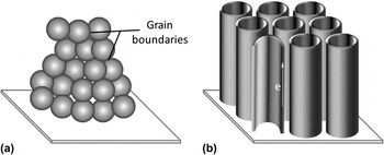
In contrast, the performance of one-dimensional (1D) nanostructures of TiOx—nanotubes or nanorods—has been reported to exhibit much better performance than nanoparticulate systems; the much lower number of grain boundaries in the 1D nanostructures is believed to allow improved charge separation as shown in Scheme 1. Also, an advantage with nanotubes compared to nanorods is the larger surface area offered; in addition to the exterior surface of tube wall, the inner cavity of tube is also available for participating in photocatalysis. Moreover, TiOxnanotubes (T–NTs) can be prepared using a simple anodization process [also referred often as anodized titanium oxide (ATO)] over a suitable Ti-based substrate. This should allow the fabrication of solar devices by roll-to-roll processing and hence boost commercial implementation.
The key difference between the (a) particulate and (b) nanotubular film architecture is the large presence of inter-particle grain boundaries as shown in this representative schematic with TiO2films as an example oxide photocatalyst.

The leading reviews on T–NTs have separately focused on T–NT. Specifically, the mechanism of T–NT formation along with dopant and additive effects has been extensively discussed. Yan et al.Reference Zhang, Xu and Yan10 have examined T–NT modification with different additives and its application to environment. Mohammad and RohaniReference Mohamed and Rohani11 have extensively written on the formation of the T–NT in different media and the effects of doping and other additives with insights on a few applications to environment remediation and photovoltaics. Schmuki and GhicovReference Ghicov and Schmuki12 have written a well-cited review on the formation of T–NT, the effects of dopants, and limited their discussions to the application of these materials to environmental remediation and photovoltaics. Grimes et al.Reference Mor, Varghese, Paulose, Shankar and Grimes13 have written an insightful article on the T–NT formation in fluoride-based electrolyte, doping effects, concluding with the applications related to photoelectrolysis and solar cells.
This review article is different in that it presents (i) important advances in the formation of T–NT on a variety of substrate geometries and (ii) a careful selection of applications of T–NT and T–NT-based composites that indicate the multifunctionality and breath of the applications using T–NT. We report two aspects related to ATO synthesis. This includes efficient utilization of Ti and electrolyte to produce nanotubes. Additionally, we have also presented a unique and lesser-known photocatalytic application of T–NT to a biological process—photocatalytic splitting of water in simulated blood.
II. SYNTHESIS OF T–NT ON VARIOUS SUBSTRATES BY ANODIZATION
A. Materials
The precursor for the synthesis of T–NT is a Ti metal substrate in various forms. Ti foils of various thickness ranging from 0.5 to 2 mm thickness (ESPI® International, Ashland, OR), wires (φ = 0.5–2 mm), coils (φ = 0.5–2 mm), and mesh (Alfa Aesar®, Ward Hill, MA or Aldrich®, St. Louis, MO) with purity >99.99% are used to prepare T–NT. Prior to anodization, the raw substrate is degreased in acetone or ethanol to remove residual organic impurities from the surface. The electrolytes for anodization vary from a completely aqueous-based composition to a blend of aqueous and organic solvent-based compositions. One common electrolyte is a fluorinated solution of ethylene glycol and deionized water with an ammonium salt. A high temperature furnace, with the option to control the annealing atmosphere using appropriate gas blends, is also required for the heat treatment of the T–NT with the intent to perform phase transformation.
B. Methods
An electrochemical equipment, i.e., potentiostat (Autolab PGSTAT 30, Riverview, FL), is used for performing the anodization. To improve the mobility of the electrolyte and to minimize mass transport issues, anodization is performed under ultrasonication. An Agilent®(E3649A, Santa Clara, CA; dual output: 0–35 V/1.4 A or 60 V/0.8 A) DC power supply is used at 10 V or in increments of 10 V over a period of 1–3 h. This process results in the presence of localized electric field that leads to the formation of the T–NT.
A key consideration is the desire to reduce the volume of electrolyte (i) to make the process economically viable during scale-up and (ii) for minimizing electrolyte mass transport limitations. The volume of electrolyte can be considerably reduced for the anodization of substrates with lesser area or more intricate shapes, e.g., Ti wires in the form of coils. In a representative lab-scale approach, a Ti wire or a coil is placed in a glass tube of 4 mm diameter and 10 cm length. A Pt wire of length 15 cm and φ = 1 mm is inserted into the glass tube. The Pt wire is bent slightly to keep the glass tube from slipping down the wire. The glass tube along with the Ti coil and the Pt wire is then placed in a 25 mL graduated cylinder filled with 25 mL of the anodization solution. The anodization conditions (i.e., voltage and duration) can be modified to prepare T–NT of different dimensions. The electrolyte can be cooled and/or replaced to avoid heat-driven physical changes in the T–NT morphology, especially when ultrasonication is used.
Following this step, the anodized T–NT sample is exposed to different annealing conditions. The annealing atmosphere varies from highly oxidative (pure oxygen) to a controlled oxidative (highly enriched nitrogen or air) conditions depending on (i) the level of purity required in the T–NT and (ii) the extent of nitrogen doping required in the T–NT (nitrogen doping is the most common approach to improve visible light activity of TiO2). The annealing temperature is varied from 350 to 600 °C depending on the extent of crystallization required in the T–NT.
So far, the use of Ti directly as a precursor for T–NT synthesis has been presented. Thin layer of Ti may also be deposited on a conductive substrate such as indium tin oxide-coated glass slide (Pilkington Libbey Owens Ford conducting glass, Toledo, OH). Physical vapor deposition can be used to from the Ti film. The quality (texture and roughness) of the deposited film and its stability depend on the chamber vacuum, the adhesiveness between the substrate and the Ti film, and the purity of the Ti source. An approach to the preparation of such Ti films is discussed in greater detail elsewhere.Reference Kar, Ryan and Subramanian14 Once the Ti film is deposited, it can be subjected to the anodization process to prepare the T–NT and then annealed, under conditions mentioned earlier, for phase transformation.
C. Surface and photoelectrochemical characterization
The surface and optical characterization of the T–NT and its composites are carried out using a set of complementary surface, optical, and electrochemical techniques. A UV–vis spectrophotometer operated under either reflectance or absorbance mode can determine the absorption characteristics of the materials. Scanning electron microscopy (SEM) complemented with energy dispersion x-ray spectroscopy detector and transmission electron microscopy complemented with a selected-area electron diffraction analyzer are used to reveal the morphology of the nanostructures and determine the composition and the phase of the nanostructures.
Photoelectrochemical characterization using potentiontstatic/galvanostatic approaches include chronoamperometry, chronopotentiometry, and cyclic voltammetry measurements; photoresponse stability and solar-to-electric conversion efficiencies are some of the common quantitative results of interest from these measurements. It is to be noted that these techniques are universal and are used irrespective of the final application of the T–NTs. Specialized characterization techniques such as Mott–Schottky and electrochemical impedance assist in determining charge separation efficiency and transport properties.
III. RESULTS AND DISCUSSIONS
A. Morphology of T–NT and anodization parameters
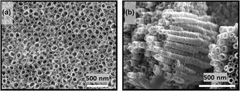
The physical features of the T–NT formed after anodization and heat treatment are shown in the SEM images of Fig. 1. The top view shows that the T–NTs are fairly identical to one another and hollowReference Sohn, Smith, Misra and Subramanian15 and are juxtaposed next to one another in an orderly manner with some intertubular spacing. The tube diameter, length, and wall thickness are varied by changing the anodization voltage, electrolyte, and/or the anodization time.
The representative images of (a) top view and (b) side view of TiO2nanotubes prepared by anodization.

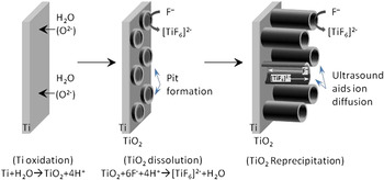
In any anodization process to form T–NT, the key steps involved can be divided as follows: (i) the formation of pits via dissolution of Ti facilitated by the O2− from the electrolyte driven under external bias, (ii) diffusion of the Ti as cation complexes toward electrode–electrolyte interface leading to a pit formation, and (iii) reorganization of the pit followed by growth of nanotubes along the periphery of the pits via the reprecipitation of the TiO2. The mechanism of the formation of the T–NT is illustrated in Scheme 2.
The diameter, length, and spacing between the tubes are determined from the cumulative effects of the electrolyte type (ionic radius), its concentration, pH adjustors, and the applied electric field. An analysis of the results of anodization in different electrolytes and electrolyte combinations (including pH adjustors) offers the following insights:
(i) The monovalent anion, fluoride, has the primary impact on the physical features of the T–NT including its diameter, length, and thickness since it is the primary carrier specie that transports the Ti from the metal frame to the electrolyte prior to reprecipitation at the pit walls:
SCHEME 2.The formation of TiO2 nanotubes on a Ti substrate involves the dissolution of Ti and re-precipitation of Ti as TiO2leading to the formation of the nanotubular architecture in the presence of an electric field.


 $${\rm{TiO}}_2 \buildrel {{\rm{HF}}} \over \longrightarrow {\rm{TiF}}_6^{2 - } \buildrel {{\rm{HF}}} \over \longleftarrow {\rm{Ti}}^{4 + }\quad. $$
(ii) The variation in the diameter starts with varying pit diameters caused by the synergistic effect between externally applied voltage along with the auxiliary anions (O2−, OH−). The anodization voltage almost exclusively determines the diameter of the T–NT, while the pH has no influence whatsoever on the diameter of the nanotubes.
(iii) As far as the spacing of the pits is concerned, the inclusion or variation in the concentration of higher order anions (SO42−, PO43−) show almost similar physical features in the T–NT. In fact, multiple anions (SO42− and PO43−) appear to have a detrimental effect and could lead to no T–NT formation. The repelling forces between the monovalent charges are strong enough (higher order valences are not really noted to perform and significant change in the nanotubes pit spacing) to ensure the pit formation and its propagation.
The diameter has been varied from ∼50 nm to several 100 nm and the length from 100 nm to several micrometers, respectively.Reference Zhuang, Lin, Lai, Sun and Li16–Reference Lai, Sun, Chen, Zhuang, Lin and Chin19 It is noteworthy to mention that T–NT with diameter of ∼350 nm is the largest reported to date.Reference Yoriya and Grimes20 The higher the diameter of the T–NT, the higher the mass transport between the nanotube mouth and the base allowing for improved kinetics in photoelectrochemical reactions.
B. Comparison of T–NT formed over different substrates
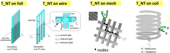
Figure 2 shows the different geometries (wires, mesh, and coil) used for the synthesis of T–NT. A representative postanodization SEM image corresponding to one of these substrates, a wire, is shown in Fig. 1(b). The dimensions of the T–NT can be varied over similar ranges as that of a foil; details can be found elsewhere.Reference Kar, Smith and Subramanian21 Furthermore, a reduction in the electrolyte volume used for anodization has no bearing on the T–NT architecture; e.g., ∼25 mL of electrolyte can be used to prepare nanotubes on coils.Reference Jaeger, Wilson and Subramanian22 The similarities among the SEM images indicate that anodization can be applied successfully toward the synthesis of T–NT on planar as well as nonplanar geometries.Reference Sohn, Smith, Misra and Subramanian15, Reference Kar, Smith and Subramanian21–Reference Smith, Kar and Subramanian24
The TiO2nanotubes can be prepared on planar (foil) and non-planar (wire, coil, or mesh) geometries using the anodization method without any change in physical features.

C. Annealing conditions and phase transformation of T–NT
As-synthesized samples often show some crystallinity before annealing. The effects of heat treatment mainly include an accentuation of the preexisting phase and/or the formation of additional phases making the T–NT polycrystalline.Reference Mohapatra, Misra, Mahajan and Raja25 TiO2, in general, is known to pass through the following phase transition pathway: amorphous → brookite → anatase → rutile.Reference Subramanian, Ni, Seebauer and Masel26 The presence of the underlying Ti substrate and the overlying crystalline nanotubes is typically noted in the x-ray diffraction.Reference Xiao, Quyang, Liu and Liang27 The preferential transformation to a desired phase based on annealing conditions is possible and reported. The T–NT phases that are typically of interest in photocatalysis are anatase and rutile, and the ratio of these phases is tunable by varying the annealing (the atmosphere and temperature) and synthesis conditions as noted in the following section.
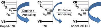
In the TiO2 system, phase transformations of amorphous TiO2 to crystalline anatase and crystalline rutile are mainly a function of temperature, mineralizers, pH, and/or dopants present in the T–NT. Specifically, these include high temperature (beyond 350 °C), presence of additives in the Ti, as well as low pH (up to 1.5). Low pH does not promote formation of irregularities in the crystal structure (such as presence of twining planes).Reference Subramanian, Ni, Seebauer and Masel26 This allows for preferential anatase formation. A further increase in the temperature results in the thermodynamically stable rutile phase formation.Reference Matthew28 The anatase-to-rutile transformation in TiO2 is influenced by conditions such as precursors composition (Ti can be pure or an alloy with other metals such as Mn or Al) and the method of synthesis of the parent oxide.Reference Kim, Park and Jeong29 Additive in the Ti can include mineralizing agents (e.g., alkali metal fluorides) and/or cation dopants (La, Zn, Al, K, Na, Ca, Ba, and Co), of the order of 1–3 wt%. While TiO2 is known to have both surface (shallow) and deep trap states, annealing temperature is known to influence the shallow surface states more than the other.Reference Palmas, Pozzo and Mascia30 The unpassivated states in the surface formed during anodization are the foremost to interact with the gases under annealing conditions. This interaction leads to a relatively higher rate of shallow trap passivation than the deep traps, as shown in Fig. 3.
Further, the inclusion of C or N via doping can determine the nature of trap site and the corresponding absorbance. C doping has been shown to favorably improve redshift in absorbance leading to more photoelectrochemical response compared to N doping.Reference Sang, Zhang, Bai, Du and Ma31 One study demonstrates that microwave heating completely transforms pure anatase to rutile at 900 °C in 30 min compared to only partial conversion (<60%) to rutile via conventional heating at 1000 °C for 30 min.Reference Borkar and Dharwadkar32 Perhaps, anodization of Ti to form porous nanostructures of amorphous TiO2followed by microwave heat treatment at selective temperatures far below 900 °C for a few minutes could retain the porous nanostructure, as well as the ratios of the anatase and rutile phases.
Annealing (heat treatment) can be applied under different controlled conditions to passivate the surface states on TiO2 nanotubes to influence its photo(electro)catalytic properties. (Ef = fermi level, ets, etd= shallow and deep trap sites for electrons, VB, CB = valence and conduction bands).

With respect to pH, it has been observed that neutral, alkaline, and mildly acidic conditions favor anatase, whereas more strongly acid environments favor rutile. Consequently, the long-term stability of the desirable anatase phase, in the presence of the high pH (12.6) electrolyteReference Patil, Shahane, Sutrave, Raut and Deshmukh33 of the photoelectrochemical (PEC) cell, should not be an issue. In essence, low processing temperatures/times and high solution pH during PEC cell activity should inhibit the transformation of anatase to rutile and maintain the desired anatase phase. One such example involving temperature-driven phase transition in T–NT has been discussed elsewhere.Reference Ma and Liu34
D. Charge separation of T–NT
When one is focusing on photogenerated charge transport, a key comparison of interest is electron transport and the catalytic properties of T–NT with that of T_NP-based films. The photocurrent measurements of nanoparticulate films of TiO2 and T–NT have been performed; in general, an external voltage-dependent enhancement in the photocurrent values by 10–40% in T–NT is reported in the literature.Reference Beranek, Tsuchiya, Sugishima, Macak, Taveira, Fujimoto, Kisch and Schmuki35 Similarly, over 20% photocatalytic activity improvement using T–NT compared to particulate films as measured from fractional conversion of pollutant is also observed.Reference Liu, Zhang, Nishimoto, Jin, Tryk, Murakami and Fujishima36–Reference Xie38 These enhancements in T–NT over their nanoparticulate counterparts are attributable to several factors but not limited to the factors:
(i) Longitudinal dimensions: T–NT having the same order of magnitude as the wave length in the UV region makes it conducive for improved light absorption;
(ii) Lower relative mass of electron: T–NT allows for faster electron transport compared to a nanoparticle; and/or
(iii) Existence of fewer interparticle grain boundaries: T–NT allows for lower losses of electrons via recombination.
IV. APPLICATIONS of T–NT and T–NT COMPOSITES
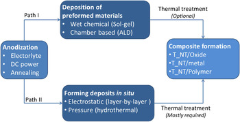
The synthesis of T–NT-based nanocomposites can be performed along two pathways. This includes using T–NT with other preformed materials to form a composite (path I) as shown in Scheme 3. An example of this approach is the deposition of metal nanoparticles or other photoactive materials such as dyes and other inorganic or organic materials on top of T–NT.Reference Kuang, Brillet, Chen, Takata, Uchida, Miura, Sumioka, Zakeeruddin and Grtzel39–Reference Wang, Guo and Li41 In the second approach, the preformed T–NT can be used as an anchor or a reactant for the nucleation, growth, and deposition or formation of other materials.Reference Murugesan, Smith and Subramanian42 A detailed discussion of the synthesis approach is beyond the scope of this paper. The remainder of this paper focuses on T–NT and T–NT-based composites and their applications in photon energy-driven processes; these include photocatalytic water splitting, pollutant decontamination, photovoltaics, environmental CO2control, and biomedical applications.
The general outline for the synthesis of composites using anodized TiO2nanotubes. (ALD = atomic layer deposition).

A. Photocatalytic water splitting using T–NT and T–NT-based composites
1. T–NT for water splitting to produce hydrogen and oxygen
Water splitting requires a theoretical energy equivalent to 1.23 eV, which may be achieved by solar-assisted excitation of electron–hole pairs in the photocatalyst. In practice, an over potential (supplied by an external bias) is required to perform water splitting. Titania mainly absorbs UV light and produces these electron–hole pairs across the conduction and valence bands, respectively, such that the redox potentials of water are straddled. The water splitting process involves water oxidation by holes to form oxygen at the anode and proton reduction by electrons to from hydrogen at the cathode. In a photocatalytic process, the anode and cathode centers coexist in the same particle, while in a photoelectrocatalytic process, these centers are distinctly separated. Several reviews have discussed water splitting in detail.Reference Bard and Fox43–Reference Matsuoka, Kitano, Takeuchi, Tsujimaru, Anpo and Thomas49
Since the optical and chemical properties of T–NT are similar to T_NPs, the basic function of T–NT is very similar to the nanoparticles. Since T–NT is constrained by its band gap to absorb only UV light, there are limited efforts for its application to photocatalytic water splitting. The application of T–NT is as an electrode promoting water splitting to produce hydrogen in 1 M KOH is well investigated.Reference Allam and El-Sayed50, Reference Li, Yu, Song, Li, Yi and Shao51 In one study, the quantum efficiency denoted by the incident-photon-to-electron conversion efficiency (IPCE) of this process was as high as 43%.Reference Zhang, Hossain and Takahashi52 Among the different method used for T–NT synthesis, anodization in ethylene glycol is reported to produce smooth tubes. This method is often recognized as the basis for highest water splitting compared to T–NT synthesized by other methods such as anodization in the absence of ultrasonication or in aqueous-based media.Reference Nam, Oh, Joo, Sarp, Cho, Nam and Yoon53 Another interesting approach involves the manipulation of the annealing temperature to produce hydrogen under no external bias conditions.Reference Sun, Yan, Wang, Guo and Ma54 Recently, under external bias, a hydrogen generation efficiency of 6.8% is reported using T–NT, which is significant compared to T_NPs of similar mass.Reference Mor, Shankar, Paulose, Varghese and Grimes55
2. T–NT-based composites for water splitting to produce hydrogen and oxygen
Additives are added to T–NT to (i) improve light absorbance, (ii) promote charge separation, and/or (iii) increase the photo(electro)catalytic activity of the T–NT-based composite. Metal ions, metal, metal oxides, inorganic nonmetals such as chalcogenides, organics such as dyes or polymers can be added to T–NT to improve water splitting.Reference Mor, Varghese, Paulose, Shankar and Grimes13, Reference Lai, Sun, Chen, Zhuang, Lin and Chin19, Reference Mor, Shankar, Paulose, Varghese and Grimes55, Reference Macak, Ghicov, Hahn, Tsuchiya and Schmuki56 In general, the additives can be prepared either by (i) Ti anodization in the presence of the desired additive (chemical doping), (ii) deposition of the material from precursors followed by chemical/heat treatment, or (iii) preformation of the additive, followed by its deposition on T–NT.Reference Macak, Barczuk, Tsuchiya, Nowakowska, Ghicov, Chojak, Bauer, Virtanen, Kulesza and Schmuki57, Reference Li, Yuan, Han, Jiang and Shangguan58 All these approaches have been explored over the last decade but a select few are mentioned below.
Strontium (Sr) doping during anodization reportedly increases photon conversion efficiency 3 timesReference Hamedani, Allam, Garmestani and El-Sayed59 and anodization of a Ti–Ru alloy demonstrates a 6-fold increase in water splitting compared to plain T–NT.Reference Roy, Das, Lee, Hahn, Ruff, Moll and Schmuki60 While electrodeposited Pt showed oxidation of seawater, T–NT alone showed negligible photocatalytic activity.Reference Nam, Oh, Joo and Yoon61 Likewise, the deposition of Pt from Pt salts (by chemical reduction using borohydrides) has shown hydrogen production in the presence of ethanol as a sacrificial agent.Reference Antony, Mathews, Ramesh, Murugesan, Dasgupta, Dhara, Dash and Tyagi62 In a similar work, Subramanian et al.Reference Raja, Smith, Kondamudi, Manivannan, Misra and Subramanian63 has demonstrated water splitting using T–NT–Pd nanocomposites using UV–vis illumination. Also, N2doping through plasma; nitrogen (N) doping using plasma treatment has been noted to demonstrate visible light activity leading to increased photocatalytic activity compared to samples without plasma treatment. At an atomic level, the treatment in the presence of a nitrogen-containing molecule (such as ammonia) allows for the introduction of N-atoms at the interstitial and/or substitutional sites leading to passivation of the defects therein along with significant redshift in the absorbance.Reference Wang, Yang, Wei, Le, Liu, Pan, Fang, Xiong and Shi64
B. Environmental pollution control using T–NT and T–NT-based composites
1. T–NT for decontamination of aqueous and gas phase pollutants
Photocatalytic degradation is one of the earliest catalytic-based applications of TiO2. Liquid and gas phase pollutants can be photodegraded by the strong oxidizing power of the valence band holes and/or hydroxyl radicals to relatively benign byproducts and eventually converted to CO2and water. The general reaction steps are as follows:
 $${\rm{TiO}}_2 \buildrel {{\rm{UV}} - {\rm{vis}}\;{\rm{light}}} \over {\hscale350%\longrightarrow} {\rm{TiO}}_2 ({\rm{e}}_{{\rm{CB}}} + {\rm{h}}_{{\rm{VB}}} )\quad,$$
 $${\rm{TiO}}_2 ({\rm{h}}_{{\rm{VB}}} ) + {\rm{waste}} \to {\rm{byproduct}}({\rm{s}}) \to {\rm{CO}}_2 + {\rm{H}}_2 {\rm{O}}{\rm{\quad.}}$$
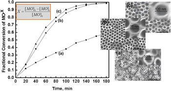
Recently, Subramanian et al.Reference Sohn, Smith, Misra and Subramanian15, Reference Kar, Smith and Subramanian21, Reference Smith, Kar and Subramanian24 has demonstrated the application of T–NT for the photodegradation of effluent species common in textile mill runoffs. It was shown that physicochemical parameters such as light intensity, dye concentration, and physical dimensions of the tube can influence the kinetics of the dye degradation process.Reference Smith, Kar and Subramanian24 In fact, it has been noted that as the diameter of the tube increases, the photodegradation of a textile dye methyl orange (MO) increases as shown in Fig. 4. This observation is attributed to the improved mass transport of MO across the length of the tubes and light activation of the photocatalyst.
The photodegradation of a common pollutant, methyl orange (MO), can be significantly enhanced by changing the diameter of the nanotubes as shown in this plot between fractional conversion of the dye (X) over 180 min.

It is well known that the application of an external bias can assist with improving separation of photogenerated charges in TiO2 films.Reference Nasr, Kamat and Hotchandani65, Reference Subramanian, Wolf and Kamat66 In another work, Subramanian et al. has demonstrated the applicability of this to T–NT films. A small bias as low as 0 V versus Ag/AgCl is sufficient to improve the conversion of a dye by a factor of at least 2.Reference Sohn, Smith, Misra and Subramanian15 The T–NT can also be used in the photodegradation of gas phase pollutants. For example, butanedione, a pollutant that can have negative health effects if inhaled excessively, was demonstrated to photodegrade over T–NTs prepared on coils.Reference Jaeger, Wilson and Subramanian22
Between photocatalytic and photoelectrocatalytic processes, the best approach to utilize T–NT for photoremediation is the photoelectrocatalytic process.Reference Li, Zhou, Lei, He, Zhang and Pan67 Yao et al. report on the photodegradation of rhodamine B, a dye, using T–NT and T_NP-based films. T–NT is 30% better than T_NP under no bias conditions.Reference Yao, Li, Chen, Jia, Wang and Wang68 However, it demonstrates almost similar photoactivity as T_NP under bias conditions. As is evident from these results, this area requires more research. It appears that the transport of dye across the tube (especially when it is sealed at the other end) is hampered leading to reduced activity. In this context, the application of a “free-standing flow through” type of T–NT has to be examined for further improvements.Reference Liu, Wang, Hoivik and Jakobsen69 Other interesting applications of T–NT for photodegradation can be found elsewhere.Reference Liu, Zhang, Nishimoto, Murakami and Fujishima37, Reference Kontos, Katsanaki, Maggos, Likodimos, Ghicov, Kim, Kunze, Vasilakos, Schmuki and Falaras70–Reference Cardoso, Lizier and Zanoni76
2. T–NT-based composites for decontamination of aqueous and gas phase pollutants
Since photodegradation involves pollutants instead of just water, additives in the T–NT are added for the same reason as discussed earlier in Sec. IV. B. 1. Due to its unique hollow geometry, the strategic deposition of additives can potentially assist with increased photocatalysis. To test this hypothesis, we have examined the applicability of T_NP deposits on T–NT and have shown that an intermediate layer of T_NPs between T–NT and a visible light absorbing CdS can in fact improve photodegradation of textile dyes. Apparently, the dispersion of CdS is facilitated by the intermediate layer of T_NPs.
Other groups have also examined the effects of including different additives alongside T–NT. These additives can include oxides, metal nanoparticles, or nonoxides. T_NP deposits on T–NT demonstrate mixed responses. For example, the UV absorbance is reportedly reduced, while the photodegradation is enhanced by deposition of T_NP.Reference Yu, Wang, Shi, Yuan, Zhao, Fang and Deng77, Reference Wender, Feil, Diaz, Ribeiro, Machado, Migowski, Weibel, Dupont and Teixeira78 The deposition of metal nanoparticles such as Ag can improve the photodegradation of a pollutant multifold.Reference Liu, Liu, Hao and Chu79, Reference Li, Zou, Qu, Zhao and Wang80 The argument in support of improved photoactivity of T–NT in the case of metals is the same as the one for T_NP: metals function as sinks for photogenerated electrons facilitating better charge separation.Reference Subramanian, Wolf and Kamat66 In another report, T–NT doped with nitrogen has been shown to perform photoreduction as well as photooxidation.Reference Macak, Ghicov, Hahn, Tsuchiya and Schmuki56, Reference In, Vesborg, Abrams, Hou and Chorkendorff81, Reference Kim, Fujimoto, Schmuki and Tsuchiya82 Also, the photodegradation of 2,3-dichlorophenol, using a polymer (polythiophene) deposited on T–NT, has been demonstrated using visible light.Reference Liang and Li83 Moreover, carbon-based materials such as fullerenes have also been shown to photodegrade pollutants on T–NT.Reference Lin, Zong, Zhou and Zhu84 T–NT composites prepared by doping are also implemented to improve photocatalytic degradation. In a recent study, the doping using boron and/or phosphor has indicated improved photocatalytic activity when terephthalic acid is used as a probe.Reference Zhou, Jin, Zhang, Wang, Yu and Peng85
C. Solar-to-electric conversion using T–NT and T–NT-based composites
1. T–NT for photovoltaic applications
Photoexcited electrons constitute the electric current, and hence, the efficacy of this process is of primary interest in photovoltaics. Titania prepared on glass supports have demonstrated efficient solar-to-electric conversion.Reference Kar, Ryan and Subramanian14 This is particularly noteworthy since only a fraction of Ti is used in a glass support compared to the amount present in a foil. The photoelectrochemical parameters offer insights into the functionality of a material for solar-to-electric conversionReference Subramanian86; one such parameter is V oc or open-circuit potential. Subramanian et al. has observed that as the diameter of the T–NT increases, the V ocincreases, which is indicative of more efficient charge separation.Reference Liang and Li83
A highly order and transparent TiO2 nanotubular film synthesized on glass has been reported as wellReference Mor, Varghese, Paulose and Grimes87; the transparency aspect can be exploited to make cells that are thinner and more efficient. The electrochemical measurements have indicated that nanotubular films demonstrate a much higher surface photovoltage compared to their particulate counterparts.Reference Zhang, Wang, Pang, Lin, Jiang and Xie88 Also, surface treatment (either heat or plasma based) has been shown to be beneficial in improving photoelectrochemical and optical absorption properties.Reference Beranek, Macak, Gartner, Meyer and Schmuki89 Furthermore, the annealing conditions can be modified to considerably alter the conductivity of the T–NT.Reference Tighineanu, Ruff, Albu, Hahn and Schmuki90 In another contribution, the application of a pulsed anodization, instead of continuous anodization approach to T–NT formation and growth, is reported to show improved photoelectrochemical properties such as photocurrent generation.Reference Chanmanee, Watcharenwong, Chenthamarakshan, Kajitvichyanukul, de Tacconi and Rajeshwar91
2. T–NT-based composites for photovoltaic applications
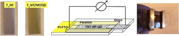
Our group has developed T–NT with different composites for photovoltaic (PV) applications.Reference Smith and Subramanian23, Reference Murugesan, Smith and Subramanian42 In the first instance, the role of CdSe nanoparticles as visible light harvesters was examined with T–NT on a mesh as the underlying substrate; an IPCE of over 25% was noted. The T–NT on a mesh with the CdSe was used to fabricate a solar cell as shown in Fig. 5, and the response was noted to be very stable. In another work, ruthenium-based dye was used as the light-harvesting agent.Reference Liu, Subramania and Misra92 This work systematically examined the influence of the physical features of the nanotubes on photovoltaic effects. In another study, T–NT was used as a precursor to form visible light absorbing bismuth titanate of the sillenite phase (Bi12TiO20).Reference Murugesan, Smith and Subramanian42 The composite thus formed, demonstrated anywhere from 10% to 40% increase in photoelectrochemical activity. This work lays the foundation for preparing similar composites using preformed T–NT.
The TiO2 nanotubes prepared on a mesh can be coated with a chalcogendide quantum dot (QD) to prepare a visible light active material and can be used to demonstrate the applicability of the composite as a photoanode in a solar cell configuration. (NP = TiO2nanoparticle deposits, Pt-FTO = Pt on F-doped tin oxide).

Other groups have also examined the application of T–NT-based composites for solar photovoltaics. A dye-sensitized solar cell prepared by deposition of dyes on a TiCl4-treated T–NT showed a very good IPCE of 7.12.Reference Ye, Xin, Lin and Lin93 Another article indicates that a sonication-assisted chemical bath deposition approach to chalcogenides demonstrates much better photoelectrochemical properties compared to other approaches to chalcogenide deposition.Reference Xie, Ali, Yoo and Cho94 Another study alludes to the possibility of exploiting the conductivity of the T–NT to electrodeposit Cu within the tube walls. Such architecture has been used as an anode in a solar cell with promising results.Reference Li, Chang, Chien and Lu95 A unique approach involving formation of chalcogenide deposits on T–NT walls by sublimation has been shown to be a simple and effective method leading to ∼30 times improved photoelectrochemical response than T–NT.Reference Gao, Sun, Hu, Ai, Zhang, Feng, Li and Peng96
D. Carbon dioxide control via conversion to hydrocarbons using T–NT and T–NT-based composites
1. T–NT for CO2 control
The interest in CO2 control stems mainly from the requirement to mitigate climate change issues. Unfortunately, CO2 is a chemically stable molecule that requires tremendous activation energy for conversion to any other form.Reference Smith, Subramanian and Viswanathan97 There has been considerable interest in exploring the photocatalytic conversion of CO2 to value-added product(s) in general and hydrocarbon fuels in particular. The photocatalytic route over TiO2 in general includes (i) water splitting to produce hydrogen and (ii) CO2activation followed by combination with hydrogen to form a hydrocarbon. The reactions are as follows:
 $${\rm{H}}_2 {\rm{O}}\buildrel {{\rm{UV}} - {\rm{vis}}} \over {\hscale250%\longrightarrow} 2{\rm{H}}^ + + {\raise0.7ex\hbox{1} \!\mathord{\left/ {\vphantom {1 2}}\right.\kern-\nulldelimiterspace}\!\lower0.7ex\hbox{2}}\,{\rm{O}}_{\rm{2}}^{2 - } \quad,$$
 $${\rm{CO}}_2 \to {\rm{activated}}{\kern 1pt} \,{\rm{radical\quad,}}$$
 $$\!\!\!{\rm{Activated}}\;{\rm{radical}} + {\rm{nH}}^ + \buildrel {{\rm{UV}} - {\rm{vis}}} \over {\hscale250%\longrightarrow} {\rm{hydrocarbons}}{\rm{\quad.}}$$
Due to the challenge associated with reaction (4), very few materials are likely candidates for CO2 conversion. Therefore, the application of T–NT to CO2 conversion is rather sparse. Furthermore, since TiO2 is limited to UV light absorbance, the yields are insignificant as well. Readers are referred to a few articles that discuss the details of CO2conversion using the photo(electro)catalytic pathways.Reference Koci, Obalova, Matejova, Placha, Lacny, Jirkovsky and Solcova98, Reference Indrakanti, Schobert and Kubicki99
2. T–NT-based composites for CO2 control
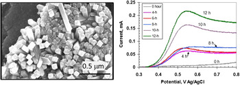
The requirement of additives is usually essential for CO2 photoreduction. The additives perform the function of CO2 molecule activation and/or increased light absorbance. The studies reported with T–NT are more focused on the latter part. In a preliminary work, our group has synthesized Pd deposits on T–NT and demonstrated the photocatalytic reduction of CO2 using this composite photocatalyst.Reference Raja, Smith, Kondamudi, Manivannan, Misra and Subramanian63 Also, as mentioned earlier, we have shown that the T–NT can be used to grow a multicomponent oxide, bismuth titanate (Bi12TiO20), as shown in Fig. 6 (left). The T–NT along with the visible light absorbing Bi12TiO20 accentuates the CO2 conversion in the presence of Pd deposits. Qualitative (cyclic voltammetry) and quantitative (liquid chromatography) analysis has indicated that the likely product is formic acid, shown using a representative set of cyclic volatammetry in Fig. 6 (right).
SEM images indicating the formation of nanocube-like Bi12TiO20 over pre-formed TiO2 nanotubes is shown. These composites can be deposited with Pd nanoparticles and used for the photocatalytic conversion of CO2to formic acid.

In related research, Grimes et al.Reference Varghese, Paulose, LaTempa and Grimes100 have examined the application of N-doped T–NT for photocatalytic CO2 conversion. The group has indicated the formation of the hydrocarbon methane in a gas phase photocatalytic reactor by the photoillumination of a mixture of CO2 and water vapor. In another work, Pt nanoparticles deposited on T–NT by a microwave technique have been used to photocatalytically convert CO2. Methane is reportedly formed from a mixture of CO2 and water vapor.Reference Feng, Sloppy, LaTemp, Paulose, Komarneni, Bao and Grimes101 Since many additives are prepared using organic precursors, the possibility of photodegradation of trace organics to form hydrocarbons and/or CO2 cannot be ruled out. Therefore, rigorous analysis of the CO2 photoreduction pathway using tracer carbon (C11 isotope) is critical to ensure CO2photoreduction.Reference Yang, Yu, Linden, Wu and Mul102
E. Light-driven biological applications using T–NT (please note, only applications of NT are given)
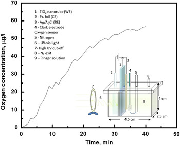
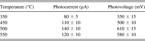
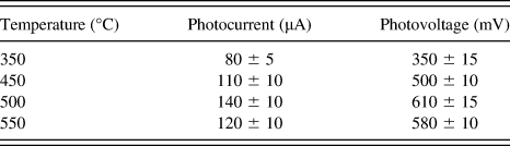
The application of TiO2 to biological and biochemical reactions under light activation can be observed in areas such as oxygenation of blood, sensing, and biodecontamination. In situ oxygenation of blood is of interest in medicine under conditions, wherein a lung becomes dysfunctional or an emergency life-threatening situation arises. Since it is well known that TiO2 can perform water splitting (producing hydrogen and oxygen), the oxygen from the process can potentially be used for the purification of the blood. In an ongoing work, our group has demonstrated the production of oxygen in a physiological fluid, Ringer solution, by photoilluminating T–NT with UV–vis light; Fig. 7 shows the preliminary data after illumination of T–NT immersed in the Ringer solution for 50 min. It indicates that the dissolved oxygen is produced by photoillumination in a simulated blood serum using T–NT and UV–vis light. We have also examined the effects of heat treatment on the T–NT performance. The Table I shows that annealing at different temperatures demonstrate increasing photoelectrochemical activity, suggesting that the oxygen evolution can be tuned by simple heat treatment.
A proof-of-concept application of anodized TiO2nanotubes for producing dissolved oxygen in a simulated blood ? Ringer solution is demonstrated. (WE, CE, RE = working, counter, and reference electrodes).

The table shows the temperature dependent changes in the photoelectrochemical responses of TiO2nanotubular film in Ringer solution.
In other works involving T–NT, the area of biocontamination is of significant interest. The microorganism Escherichia coli (E. coli) is a biocontaminant as it can exist in food products and can be contracted by ingestion, causing extensive damage to human health. The strong oxidizing hole, produced upon photoillumination of T–NT, can deactivate E. coli cells.Reference Baram, Starosvetsky, Starosvetsky, Epshtein, Armon and Ein-Eli103 The presence of Ag-based additives can further improve E. coli elimination compared to bare T–NT.Reference Hou, Li, Zhao, Chen and Rastor104 This process is therefore highly attractive to sanitize food products. Also, the application of T–NT for the controlled destruction of cancer cells has been examined, and the results have shown that anodized T–NT foils destroy the DNA strands of the cancer cell upon UV illumination.Reference Yu, Hu, Wang, Hsu, Tsai, Chen, Liu, Lin and Chen105 However, there is a major challenge to large-scale application of T–NT or any photocatalytic processes in the presence of biological fluids. Biological fluids often contain very small femtomolar concentrations of other components critical physiological processes. Oxidizing species formed during the photocatalytic process can alter their composition and negatively interfere with physiological processes. It is therefore important to determine how strong oxidizing species and UV illumination influence the composition and stability of these components that exist in such small concentration.
V. CONCLUSION
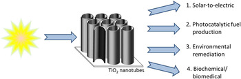
The 1D T–NTs have matured into a highly promising and reliable material with multifunctional optical, surface, and electronic properties that can be extensively used in a photocatalytic processes. Scheme 4 shows the breath of the application of T–NT in various areas related to light-activated applications. The utilization of this specific form of TIO2is significantly advantageous from the fact that it can be synthesized by anodization on different substrates and with different geometries. Further, the use of anodization as a tool is highly economical since it is simple, inexpensive, and scalable. By outlining the different light-driven applications of T–NT (significant parts of this paper reviewing some of the group’s contribution in this area), this article emphasizes the need to look at T–NT as a promising material with enormous potential in energy, biomedicine, and environment-based applications. It is emphasized that some application areas are relatively more mature than others, which leads to the recognition that research into the application of T–NT and its composites is expected to grow. At the same time, the potential for new areas of light-driven T–NT-based applications, hitherto unexplored, is also expected to emerge in the near term.
The multi-functionality and benefits of using TiO2nanotubes is evident in various areas and its usefulness is successfully demonstrated in multiple applications.

ACKNOWLEDGMENTS
This work highlights the contributions from the works of Subramanian group members—York smith, Sankaran Murugesan, Yon Sun Sohn, Ryan Pando, Winn Wilson, Bratindranath Mukerjee, and Vance Jaeger. The Subramanian group would like to acknowledge DOE and NSF for the funding that led to the completion of this work. The Dey group acknowledges the assistance of and availability of commercial-scale processing tools in Praxair Electronics (Pheonix, AZ) for the timely completion of Tara Collins’ honors thesis on “Next Generation of Anodic Coatings” and support of the electron microscopy center at Arizona State University.