Nomenclature
-
 $x$
-
state variable at any time (e.g., pressure, flow rate) [variable units]
-
$\bar x$
-
steady-state value of the state variable [variable units]
-
${\rm{\delta }}x$
-
dimensionless deviation of the state variable [dimensionless]
-
${\rm{\Delta }}x$
-
absolute deviation of the state variable [variable units]
-
$p$
-
pressure [Pa]
-
${q_{m1}},{q_{m2}}$
-
inlet and outlet mass flow rates, respectively [kg/s]
-
$s$
-
laplace operator [dimensionless]
-
$V$
-
cavity volume [m3]
-
$a$
-
fluid speed of sound [m/s]
-
$M$
-
module transfer matrix [dimensionless]
-
${p_u},{p_d}$
-
upstream and downstream pressure, respectively [Pa]
-
${q_u},{q_d}$
-
upstream and downstream flow rate, respectively [kg/s]
-
${\rm{\rho }}$
-
fluid density [kg/m³]
-
${Z_c}$
-
pipeline characteristic impedance [kg/(m2·s)]
-
${\rm{\gamma }}$
-
propagation operator [dimensionless]
-
$A$
-
average cross-sectional area of the pipeline flow channel [m²]
-
$H$
-
centrifugal pump head [m]
-
$C$
-
fitting parameters for pump head [variable units]
-
$n$
-
current rotational speed of the pump [rpm]
-
${n_0}$
-
rated rotational speed of the pump [rpm]
-
$Q$
-
propellant volumetric flow rate [m³/s]
-
${Q_0}$
-
rated volumetric flow rate [m³/s]
-
$l$
-
injector length [m]
-
$v$
-
average flow velocity inside the injector [m/s]
-
${p_i},{p_o}$
-
average inlet and outlet pressures of the injector [Pa]
-
$r$
-
steady-state mixture ratio of the combustion assembly [dimensionless]
-
$\phi $
-
dimensionless slope of combustion product temperature versus propellant mixture ratio [dimensionless]
-
${\rm{\tau }}$
-
combustion time lag [s]
-
$u$
-
steady-state gas flow velocity [m/s]
-
${a_g}$
-
gas speed of sound [m/s]
-
${l_g}$
-
gas flow path length [m]
-
${M_g}$
-
steady-state Mach number of the gas [dimensionless]
-
${\rm{\kappa }}$
-
gas isentropic exponent [dimensionless]


1.0 Introduction
The frequency characteristics of rocket engines are a critical aspect of their design and operation, defining how these complex systems respond to oscillatory inputs across a spectrum of frequencies. This analysis is particularly vital for engines utilising the gas generator cycle, where a separate combustion process powers a turbine to drive propellant pumps, introducing intricate dynamic interactions. Understanding these characteristics enables engineers to predict and mitigate phenomena such as combustion instability, pressure oscillations and structural resonance, all of which can compromise performance and safety if not adequately controlled. The significance of frequency characteristics lies in their ability to inform stability assessments, optimise performance and enhance the reliability of rocket propulsion systems under diverse operating conditions.
In rocket engines with gas generator cycles, frequency characteristics analysis is essential due to the interplay between subsystems such as the combustion chamber, fuel supply lines and turbine-driven pumps. Resonance frequencies, if excited, can amplify oscillations, potentially leading to structural fatigue or failure [Reference Huang, Huang and Hu1]. Research has demonstrated that operating condition variations, such as changes in mass flow rate or pressure, significantly influence these frequencies and their damping properties [Reference Yang, Jin, Qi and Cai2, Reference Jin, Shang and Cai3]. Combustion instability, a well-documented challenge, often manifests as pressure oscillations that couple with acoustic modes, a phenomenon extensively studied in liquid rocket engines [Reference Peng, Weng, Bai, Li, Ma, Jiang, Wang and Hu4]. The gas generator cycle exacerbates this complexity by introducing additional dynamic elements, such as gas-driven turbine pumps, which affect the frequency response of liquid oxygen paths [Reference He, Xing and Xu5].
Frequency characteristics analysis is vital for gas generator cycle engines, where subsystem interactions amplify longitudinal and radial instabilities, such as low-frequency chug (<500 Hz) and high-frequency screech (>1000 Hz) [Reference Huang, Huang and Hu1, Reference Dong, Tan, He, Xing and Zhao6–Reference Dong, Tan, Xing, Xu and Li8]. Prior studies identified multi-tier resonance frequencies in supply systems through hydraulic excitation [Reference Dong, Tan, He, Xing and Zhao6], entropy wave effects during transients via modular modeling [Reference Zhang, Zhang and Zhang7], and operating frequency influences from gas supply methods [Reference Peng, Zhong, Chen and Li9]. Low-frequency instabilities in staged combustion [Reference Peng, Zhong, Chen and Li9], mid-to-high-frequency supply system responses [Reference Dong, Tan, Xing, Xu and Li8], and dome-combustion coupling via time-frequency analyses [Reference Schulze and Sattelmayer10] were explored, alongside nozzle swing effects [Reference Zhang, Wang, Li, Han and Wang11], gas-liquid injector instabilities [Reference Shi, Zhu, Cheng, Li and Hou12, Reference Zhu, Li, Xie, Wang and Ma13], turbine pump dynamics [Reference He, Xing and Xu5], swirling jet condensation [Reference Cong, Han, Zhou, Sun and Xi14], pintle injector responses [Reference Zhao, Yu, Li and Zhou15], combustion modes [Reference Tian, Zhao, Zhang, Fu and Shi16], perturbation inlets [Reference Chen, Si, Hu, Jin and Zhu17] and acoustic signatures [Reference Popenhagen and Garcés18]. Advanced simulations [Reference Zhu, Li, Wang, Xie and Ma19], sensor-based validation [Reference Yang, Gao and Wu20, Reference Wang, Shen, Hu and Zhou21], control strategies [Reference Avdieiev and Alexandrov22], nonlinear instability growth [Reference Ren, Guo, Feng, Lin, Tong, Liu and Nie23] and time-varying system stability [Reference Li, Bao, Wei, Hou and Shi24] addressed multiphysics challenges, with spray combustion [Reference Peng, Cao, Cheng, Bai, Li, Li and Liao25], flame stabilisation [Reference Cao, Cui, Cheng, Bai and Li26] and structural vibrations [Reference Su and Gong27] underscoring practical relevance.
This study advances beyond time-domain analyses [Reference Huang, Huang and Hu1, Reference Dong, Tan, Xing, Xu and Li8, Reference Cai, Fang, Zheng, Tong, Chen and Wang28] by using linearised frequency-domain modeling to simulate three forced oscillation scenarios, quantifying parametric sensitivities (e.g., pipeline length, injector pressure drop) for stability mitigation, unlike single-component studies [Reference He, Xing and Xu5, Reference Biryukov, Nazarov and Tsarapkin29–Reference Khan and Qamar32]. System parameter optimisation [Reference Cai, Fang, Zheng, Tong, Chen and Wang28], stability reserve algorithms [Reference Biryukov, Nazarov and Tsarapkin29], pogo vibration modeling [Reference Wang, Shujun, Jinfan, Yuming and Zhigang30] and resonator-based analyses [Reference Cárdenas-Miranda and Polifke31] are extended to propose reusable rocket designs [Reference Khan and Qamar32].
This paper is structured as follows: Section 2 details engine composition, models and validation; Section 3 analyses frequency responses; Section 4 evaluates parametric effects; Section 5 summarises findings. Results show oxidiser-driven acoustic responses (0–2000 Hz) in the thrust chamber, fuel-driven low-frequency gas generator responses and stability margin gains (1.6% via 20% pressure drop increase), guiding high-thrust propulsion design.
2.0 Modeling and validation
2.1 Composition of gas generator cycle liquid engine
The gas generator cycle liquid rocket engine, as illustrated in the schematic diagram (Fig. 1), constitutes the primary research object in this study. Operating on the principle of component independence – where each subsystem maintains self-sustaining functionality under specified boundary conditions – this engine is systematically decomposed into interconnected yet autonomous key components.
The gas generator cycle liquid rocket engine.

These include:
-
• Liquid pipelines that facilitate propellant flow through pre-pump lines, oxidiser and fuel main lines, oxidiser and fuel bypass lines, oxidiser cooling jackets (this configuration is employed in specific propellant combinations), main valve inlet lines, and bypass valve inlet lines.
-
• The turbopump assembly, which integrates the gas generator for hot gas production, the gas turbine for power extraction, the rotor for mechanical linkage, and both oxidiser and fuel pumps for pressurisation.
-
• Valves comprising oxidiser and fuel main valves alongside their bypass counterparts for controlled propellant routing.
-
• Flow regulation components featuring oxidiser and fuel main cavitation venturis as well as bypass cavitation venturis to manage flow stability.
-
• The thrust chamber, encompassing the combustion chamber with its head cavity and injector for propellant mixing and ignition, extended by the nozzle for exhaust expansion.
-
• The gas generator, structurally analogous to the thrust chamber but omitting the nozzle, thus focusing on gas production for turbine drive.
-
• The pyrotechnic starter for initial ignition.
Further disassembly of these components into elemental constituents, ordered from higher to lower complexity, reveals structures such as:
-
• The thrust chamber’s propellant head cavity, injector, combustion chamber, and nozzle.
-
• The turbopump’s turbine, centrifugal pumps, and rotor.
-
• The gas generator’s propellant head cavity, injector, and combustion chamber.
-
• Valves with their throttling elements and fore-and-aft cavities.
-
• Cavitation venturis incorporating similar cavities.
-
• Straightforward liquid pipelines.
-
• The standalone pyrotechnic starter.
Characteristic features of this configuration encompass efficient high-pressure propellant delivery through centrifugal pumps, partial propellant combustion in the gas generator to energise the turbine while exhausting overboard for cycle simplicity, and integrated flow control via orifices and cavitation venturis to prevent cavitation-induced instabilities, thereby enhancing overall reliability and performance in demanding propulsion scenarios.
2.2 Linearised frequency-domain model
Based on the small-perturbation linearisation method, the nonlinear differential equations in the dynamic characteristic simulations are linearised around the engine’s steady-state operating parameters and subjected to Laplace transformation, establishing frequency-domain simulation models for selected modules [Reference Xu and Liu33].
For computational convenience, each state variable (e.g., pressure, flow rate) is expressed in terms of its steady-state value and dimensionless deviation, as follows:
 \begin{align}x = \bar x + \delta x \cdot \bar x\end{align}
where x represents the value of the state variable at any time,
 $\bar x$
denotes its steady-state value,
 $\delta x = \Delta x/\bar x$
is the dimensionless deviation (dimensionless fluctuation) and Δx is the absolute deviation.
Substituting the processed state variables into the original differential equations yields incremental equations composed of equilibrium terms and dimensionless deviations. These incremental equations are then Laplace-transformed to form linear equations involving complex variables. For example, an equation describing components in the system, such as feed system cavities, characterised solely by their volume properties that influence dynamic behavior through compressibility effects, is given by:
 \begin{align}\frac{V}{{{a^2}}}\frac{{dp}}{{dt}} = \left( {{q_{m1}}{ - q_{m2}}} \right)\end{align}
where q m1 and q m2 are the inlet and outlet mass flow rates.
Applying the Laplace transform, with the initial condition
 $p\!\left( {{0^ + }} \right)$
at
 $t = {0^ + }$
, and using
 $\mathcal{L}\!\left\{ {\frac{{dp}}{{dt}}} \right\} = sP\!\left( s \right) - p\!\left( {{0^ + }} \right)$
, the transform yields:
 \begin{align}\frac{V}{{{a^2}}}\!\left[ {sP\!\left( s \right) - p\!\left( {{0^ + }} \right)} \right] = {Q_{m1}}\!\left( s \right) - {Q_{m2}}\!\left( s \right)\end{align}
Where
 ${Q_{m1}}\!\left( s \right)$
and
 ${Q_{m2}}\!\left( s \right)$
are the Laplace transforms of
 ${q_{m1}}$
and
 ${q_{m2}}$
, respectively, and s is the Laplace operator. Solving for
 $P\!\left( s \right)$
, the transfer function from net flow to pressure is:
 \begin{align}P\!\!\left( s \right) = \frac{{{a^2}}}{{Vs}} \cdot \!\left[ {{Q_{m1}}\!\left( s \right) - {Q_{m2}}\!\left( s \right)} \right] + \frac{{p\!\left( {{0^ + }} \right)}}{s}\end{align}
This transfer function quantifies the pressure response to net flow variations and is used to interconnect modules in the frequency-domain model. To enable interconnection of different modules into a system, the frequency-domain equations are transformed into transfer matrices that link upstream and downstream parameters, expressed as:
 \begin{align}\!\left[ {\begin{array}{*{20}{c}}{\delta {x_e}}\\[5pt] {\delta {y_e}}\\[5pt] \vdots \end{array}} \right] = M \cdot \!\left[ {\begin{array}{*{20}{c}}{\delta {x_i}}\\[5pt] {\delta {y_i}}\\[5pt] \vdots \end{array}} \right]\end{align}
where the left side of the equation represents the downstream dimensionless state variables, M is the module’s transfer matrix, and the right side corresponds to the upstream dimensionless state variables.
Since frequency-domain analysis is based on the engine having entered steady-state operation, the pyrotechnic starter is excluded from the modeling scope. The cavitation venturi is designed to induce controlled cavitation as a flow regulation mechanism, stabilising propellant flow and preventing upstream propagation of pressure disturbances in the gas generator cycle engine, thereby enhancing system reliability. It is modeled as a closed-end boundary or a constant flow resistance, functioning as a single-resistive element in the frequency-domain analysis. Components such as the nozzle and turbine are regarded as acoustic boundaries in the gas flow path and are not modeled separately. The rotor couples the turbine and centrifugal pump, integrating liquid and gas paths; incorporating rotor frequency characteristics would complicate the formation of solvable equations, hindering system frequency response analysis. Given that the focus of this frequency-domain analysis is on oscillations in the liquid and gas paths, rotor dynamics are not considered. The frequency-domain model for one-dimensional liquid pipelines is derived directly from differential equations via Laplace transformation, differing from the time-domain characteristic finite element method, necessitating separate modeling of various cavities in the pipeline. Due to the unique frequency response characteristics of the ‘liquid-liquid’ injector, it cannot share equations with ordinary throttling elements and requires independent modeling. The target engine utilises a direct-impinging injector, with its length much shorter than the liquid wavelength, allowing it to be treated as a lumped-parameter inertial element. This model does not account for surface tension or the frequency of droplet formation, which may influence combustion instabilities in nonlinear or high-frequency regimes, representing a limitation of the current study.
2.3 Model validation
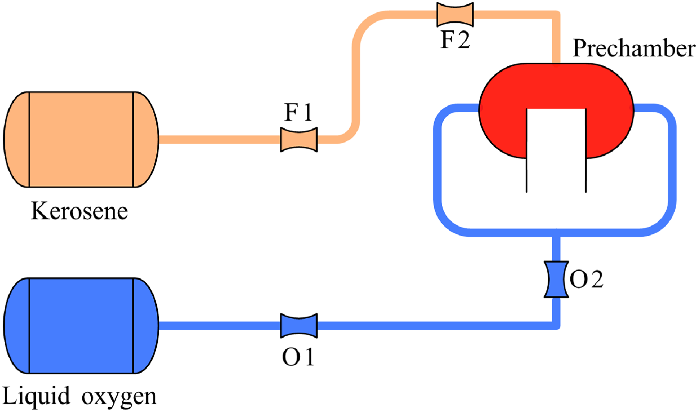
Dong et al. investigated the supply system of a liquid oxygen-kerosene rocket engine, structured as shown in Fig. 2 [Reference Dong, Tan, Xing, Xu and Li8].
Liquid rocket engine feed system (real system).

For a more precise comparison, the ‘supply system outlet flow response’ curve from the literature is selected and compared against results from this study, as shown in Fig. 3. Similarly, the system flow mode shape at 187.5 Hz (the system’s second-order resonant frequency) is compared, with results in Fig. 4.
Theoretical outlet mass flow response characteristics of a simulated liquid rocket engine feed system, with frequency (Hz) on the x-axis and dimensionless flow response amplitude on the y-axis. Outlet mass flow response (red line) characteristics of a simulated liquid fuel rocket engine. Data (black circles) reproduced from Reference [Reference Dong, Tan, Xing, Xu and Li8].

System flow mode shape at the second-order resonant frequency (187.5 Hz) for a simulated liquid rocket engine feed system, with pipeline position (m) on the x-axis and dimensionless flow amplitude on the y-axis. Outlet mass flow response (red line) characteristics of a simulated liquid fuel rocket engine. Data (black circles) reproduced from Reference [Reference Dong, Tan, Xing, Xu and Li8].

From the outlet flow response, the resonant frequencies (frequencies at peaks) obtained in this study match the literature values, but discrepancies exist in response values at peaks and valleys, with relative errors of 0.73% at peaks and 2.23% at valleys. This arises because the supply system’s resonant frequencies depend on the relative magnitudes of throttling orifice impedances and pipeline characteristic impedance, determining resonance frequencies independently of specific pressure drop values. However, specific pressure drop values affect amplitudes, i.e., response values. Since the literature provides only relative impedance relationships without specific pressure drop values, the resonant frequencies align in the flow response curves, but amplitudes differ. A similar phenomenon appears in the second-order flow mode shape curve, manifesting as offsets in amplitude peak and valley positions, with peak offsets of 2.05% and valley offsets of 3.85%. In summary, the model and simulation method in this study are deemed feasible.
3.0 Analysis of frequency response chacateristics
3.1 Models for frequency response characteristics
This section outlines frequency response models for three forced oscillation scenarios in a liquid rocket engine, using lineariSed frequency-domain approaches with tailored boundary conditions to simulate realistic perturbations.
3.1.1 Response of the supply system to thrust chamber pressure disturbances
The main path cavitation venturi, positioned after the secondary path branch, isolates thrust chamber pressure disturbances, preventing upstream propagation to the pump outlet. Thus, only the post-venturi main supply system is analysed, with the venturi in cavitating mode acting as a closed-end boundary (flow depends solely on upstream pressure). Pressure disturbances are applied at the thrust chamber outlet, propagating upstream without feedback loops due to venturi isolation.
3.1.2 Response of the combustion components to fluid disturbances
Upstream fluid disturbances cause mixture ratio fluctuations in the thrust chamber and gas generator, altering heat release and inducing combustion zone pressure oscillations. Both components are modeled under choked boundary conditions at the throat or contraction section, where the sonic plane reflects gas pressure oscillations. Inlet flow rate fluctuations (oxidiser and fuel, via linear superposition) simulate unsteady injection, driving acoustic modes.
3.1.3 Response of the combustion components to pump speed disturbances
Pump speed fluctuations generate parameter variations in outlet flow rate and pressure, which transmit through the injector faceplate to the supply system. Under the combined action of outlet faceplate parameter fluctuations and the throat acoustic boundaries, pressure fluctuations arise within the combustion components. Accordingly, the simulation objects comprise the post-pump supply system and the thrust chamber, encompassing both the post-pump main path supply system and the secondary path supply system.
Pressure fluctuations in the combustion components stem from flow and pressure disturbances in the supply system. However, since pump speed fluctuations simultaneously impact both main and secondary paths, boundary conditions must be assigned to the secondary path when analysing the thrust chamber response (and vice versa for the gas generator) to close the equation set. The venturi outlet is adopted as an open-end boundary condition, approximating zero pressure fluctuation at the outlet to reflect the venturi’s isolation of downstream disturbances.
Given that pump pulsations concurrently affect both main and secondary paths, thereby providing a flow pulsation source to the combustion components, the transfer matrix linking rotational speed pulsations to combustion component pressure pulsations requires additional derivation. The detailed process is as follows:
First, based on the system composition sequence, derive the transfer matrices connecting the injector outlet parameters to the pump inlet parameters, as given by Equations (4) and (5):
 \begin{align}\!\left[ {\begin{array}{*{20}{c}}{\delta {P_g}}\\[5pt] {\delta {q_{io}}}\end{array}} \right] = {M_{sys,o}} \cdot \!\left[ {\begin{array}{*{20}{c}}{\delta {P_{opi}}}\\[5pt] {\delta {q_{opi}}}\\[5pt] {\delta n}\end{array}} \right]\;\;\!\left[ {\begin{array}{*{20}{c}}{\delta {P_g}}\\[5pt] {\delta {q_{if}}}\end{array}} \right] = {M_{sys,f}} \cdot \!\left[ {\begin{array}{*{20}{c}}{\delta {P_{fpi}}}\\[5pt] {\delta {q_{fpi}}}\\[5pt] {\delta n}\end{array}} \right]\end{align}
where δP g is the combustion component pressure perturbation; δP io and δP if are the oxidiser and fuel injector flow perturbations, respectively; M sys,o and M sys,f are the transfer matrices for the oxidiser and fuel systems; δP opi and δP fpi are the oxidiser and fuel pump inlet pressure perturbations; δP opi and δP fpi are the oxidiser and fuel pump inlet flows; and δn is the pump speed perturbation.
 \begin{align}\!\left\{ {\begin{array}{*{20}{c}}{\delta {P_g} = {M_{sys,f}}\!\left( {1,2} \right) \cdot \delta {q_{fpi}} + {M_{sys,f}}\!\left( {1,3} \right) \cdot \delta n}\\[5pt] {\delta {q_{if}} = {M_{sys,f}}\!\left( {2,2} \right) \cdot \delta {q_{fpi}} + {M_{sys,f}}\!\left( {2,3} \right) \cdot \delta n}\\[5pt] {\delta {P_g} = {M_{sys,o}}\!\left( {1,2} \right) \cdot \delta {q_{opi}} + {M_{sys,o}}\!\left( {1,3} \right) \cdot \delta n}\\[5pt] {\delta {q_{io}} = {M_{sys,o}}\!\left( {2,2} \right) \cdot \delta {q_{opi}} + {M_{sys,o}}\!\left( {2,3} \right) \cdot \delta n}\end{array}} \right.\end{align}
Express the injector outlet flow perturbations in terms of speed perturbation and combustion component pressure perturbation:
 \begin{align}\!\left\{ {\begin{array}{*{20}{c}}{\delta {q_{io}} = {M_{sys,o}}\!\left( {2,2} \right) \cdot \dfrac{{\delta {P_g} - {M_{sys,o}}\!\left( {1,3} \right) \cdot \delta n}}{{{M_{sys,o}}\!\left( {1,2} \right)}} + {M_{sys,o}}\!\left( {2,3} \right) \cdot \delta n}\\[9pt] {\delta {q_{if}} = {M_{sys,f}}\!\left( {2,2} \right) \cdot \dfrac{{\delta {P_g} - {M_{sys,f}}\!\left( {1,3} \right) \cdot \delta n}}{{{M_{sys,f}}\!\left( {1,2} \right)}} + {M_{sys,f}}\!\left( {2,3} \right) \cdot \delta n}\end{array}} \right.\end{align}
Combine with the choked boundary conditions to solve for the transfer function equation linking turbopump speed perturbations to thrust chamber pressure fluctuations:
 \begin{align}0 = H \cdot \!\left[ {\begin{array}{*{20}{c}}{\delta {P_g}}\\[5pt] {\delta {q_{io}}}\\[5pt] {\delta {q_{if}}}\end{array}} \right] \Rightarrow H\!\left( 1 \right) \cdot \delta {P_g} + H\!\left( 2 \right) \cdot \delta {q_{io}} + H\!\left( 3 \right) \cdot \delta {q_{if}} = 0\end{align}
 \begin{align}\begin{array}{*{20}{c}}{\delta {P_g} \cdot \!\left( {H\!\left( 1 \right) + H\!\left( 2 \right) \cdot \dfrac{{{M_{sys,o}}\!\left( {2,2} \right)}}{{{M_{sys,o}}\!\left( {1,2} \right)}} + H\!\left( 3 \right) \cdot \dfrac{{{M_{sys,f}}\!\left( {2,2} \right)}}{{{M_{sys,f}}\!\left( {1,2} \right)}}} \right) + }\\[12pt] {\delta n \cdot \!\left\{ {\begin{array}{*{20}{c}}{H\!\left( 2 \right) \cdot {M_{sys,o}}\!\left( {2,3} \right) + H\!\left( 3 \right) \cdot {M_{sys,f}}\!\left( {2,3} \right) - }\\[5pt] {H\!\left( 2 \right) \cdot \dfrac{{{M_{sys,o}}\!\left( {2,2} \right)}}{{{M_{sys,o}}\!\left( {1,2} \right)}} \cdot {M_{sys,o}}\!\left( {1,3} \right) - }\\[11pt] {H\!\left( 3 \right) \cdot \dfrac{{{M_{sys,f}}\!\left( {2,2} \right)}}{{{M_{sys,f}}\!\left( {1,2} \right)}} \cdot {M_{sys,f}}\!\left( {1,3} \right)}\end{array}} \right\} = 0}\end{array}\end{align}
 \begin{align}\!\left\{ {\begin{array}{*{20}{c}}{A1 = H\!\left( 1 \right) + \left( 2 \right) \cdot \dfrac{{{M_{sys,o}}\!\left( {2,2} \right)}}{{{M_{sys,o}}\!\left( {1,2} \right)}} + H\!\left( 3 \right) \cdot \dfrac{{{M_{sys,f}}\!\left( {2,2} \right)}}{{{M_{sys,f}}\!\left( {1,2} \right)}}}\\[9pt] {A2 = H\!\left( 2 \right) \cdot {M_{sys,o}}\!\left( {2,3} \right) + H\!\left( 3 \right) \cdot {M_{sys,f}}\!\left( {2,3} \right) - H\!\left( 2 \right) \cdot \dfrac{{{M_{sys,o}}\!\left( {2,2} \right)}}{{{M_{sys,o}}\!\left( {1,2} \right)}} \cdot {M_{sys,o}}\!\left( {1,3} \right)}\\[5pt] { - H\!\left( 3 \right) \cdot \dfrac{{{M_{sys,f}}\!\left( {2,2} \right)}}{{{M_{sys,f}}\!\left( {1,2} \right)}} \cdot {M_{sys,f}}\!\left( {1,3} \right)}\end{array}} \right.\end{align}
 \begin{align}\frac{{\delta {P_g}}}{{\delta n}} = - \frac{{A2}}{{A1}}\end{align}
3.2 Simulation results of frequency response characteristics
This subsection presents the simulation results from the frequency-domain analyses of the aforementioned models, conducted over the 0–2000 Hz range (or adjusted as needed). The results elucidate the amplitude-frequency responses, mode shapes, and key dynamic behaviours, providing insights into the system’s oscillatory tendencies.
3.2.1 Supply system response to thrust chamber pressure disturbances
Simulations of the supply system’s response to thrust chamber pressure disturbances yield the following frequency responses.
The injector admittance and head cavity pressure response are plotted as amplitude-frequency curves in Fig. 5.
Theoretical injector admittance and head cavity pressure response in a gas generator cycle liquid rocket engine, with frequency (Hz) on the x-axis and dimensionless admittance or pressure amplitude on the y-axis. (a1) Oxidiser. (a2) Fuel. (a) Amplitude-frequency curve of injection admittance (b1) Oxidiser. (b2) Fuel. (b) Amplitude-frequency curve of head cavity pressure response.

From the injector admittance amplitude-frequency curves (Fig. 5(a)), the flow pulsation amplitude ranges for the oxidiser and fuel paths are comparable. As the disturbance frequency increases, the oxidiser path admittance exhibits a distinct overall increasing trend. In contrast, the fuel path admittance (Fig. 5(a2)) shows a significant dip at 1200 Hz, corresponding to a peak in the fuel flow rate response, a key finding indicating potential resonance coupling that warrants further investigation for stability optimisation.
With rising thrust chamber pressure disturbance frequency, the amplitude of pressure pulsations in the oxidiser head cavity (Fig. 5(b1)) generally declines, while the fuel head cavity response (Fig. 5(b2)) shows moderate variations. This is attributable to the presence of both head and collector cavities in the oxidiser path, whose compressibility mitigates pressure and flow pulsations, enhancing damping at higher frequencies.
3.2.2 Combustion components’ response to fluid disturbances
Simulations of the thrust chamber’s pressure response to main path flow disturbances, applying linear superposition for oxidiser and fuel flow pulsations separately, yield results in Fig. 6.
Theoretical pressure response of thrust chamber to fluid disturbances, with frequency (Hz) on the x-axis and pressure amplitude on the y-axis. (a) Oxidiser. (b) Fuel.

Simulations of the gas generator’s pressure response to secondary path flow disturbances, with linear superposition, are shown in Fig. 7.
Theoretical pressure response of gas generator to fluid disturbances, with frequency (Hz) on the x-axis and pressure amplitude on the y-axis. (a) Oxidiser. (b) Fuel.

For the thrust chamber, within 0–2000 Hz, pressure pulsations induced by oxidiser flow disturbances initially decrease then increase, reflecting prominent acoustic oscillation characteristics. In ranges below 670 Hz and above 1200 Hz, oxidiser-induced pulsations exceed those from fuel. This is because, at the thrust chamber’s nominal mixture ratio, the dimensionless slope of gas temperature versus mixture ratio is close to 0 (
 ${\rm{\psi }}$
= 0.1929), positioning the oxidiser, with its larger nominal flow, as the primary oscillation driver. This prioritises the oxidiser supply system-thrust chamber coupled system for subsequent stability analyses.
Compared to the thrust chamber, gas generator pressure oscillations are more low-frequency dominant, with minor rebounds above 500 Hz and negligible second-order effects. Contrarily, fuel drives pulsations here. Theoretically, in fuel-rich gas generator mode, oxidiser flow pulsations should dominate due to mixture ratio and total flow impacts; however, at nominal ratios, the slope is even closer to 0 than in the combustor(
 $\psi $
= 0.0975), minimising temperature variations from mixing, thus elevating fuel’s role in pressure pulsations.
3.2.3 Combustion components’ response to pump speed disturbances
With pump speed as the perturbation source, thrust chamber pressure responses are simulated over 0–2000 Hz, and gas generator over 0–1000 Hz, yielding results in Fig. 8.
Theoretical pressure response of combustion components to pump speed disturbances in a gas generator cycle liquid rocket engine, with frequency (Hz) on the x-axis and pressure amplitude on the y-axis. Note that graphs (a) and (b) use different y-axis scales to highlight distinct modal behaviours. (a) Thrust chamber. (b) Gas generator.

The gas generator’s response within 100 Hz significantly surpasses that of the thrust chamber, displaying marked low-frequency traits with a first-order resonance at 78 Hz. As the power source driving the system, substantial gas generator pressure oscillations can induce cascading effects in turbopumps and rotors, exacerbating pump speed oscillations and leading to sustained engine instability.
The thrust chamber’s response shows an overall decrease-then-increase trend, with local resonances at 184 Hz and 1918 Hz, underscoring evident acoustic features.
4.0 Analysis of influencing factors on frequency response characteristics
This section explores the sensitivities of the engine’s frequency responses to key parametric variations, building on the baseline simulations in Section 3. By systematically altering feed system geometries, injector characteristics and chamber parameters, we uncover underlying mechanisms driving oscillatory behaviours. These analyses not only validate the model’s robustness but also highlight design trade-offs, such as balancing stability margins against operational efficiency. Insights drawn here align with established propulsion literature, where parametric tuning is pivotal for mitigating instabilities in cycles like the gas generator, and extend to emerging applications in reusable rockets, where dynamic loads are amplified during transients.
4.1 Impact of feed system variations on frequency response
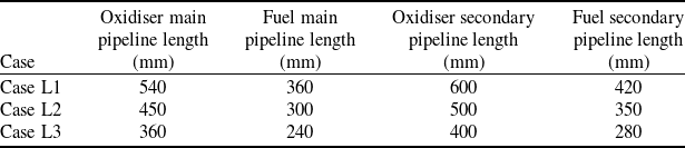
Changes in pipeline lengths – specifically the main system segment from post-venturi to pre-main valve and the secondary system from post-pump to pre-venturi – significantly alter the system’s frequency characteristics. Simulations compare three conditions: 120%, 100% and 80% of nominal main and secondary pipeline lengths, as detailed in Table 1. The analyses encompass the main supply system’s response to thrust chamber pressure pulsations, combustion components’ response to pump speed disturbances and the coupled stability of the thrust chamber-supply system.
Configuration parameters for pipeline length variations in the oxidiser and fuel supply systems, detailing cases with lengths at 80%, 100%, and 120% of the Case L2, designed to evaluate frequency response shifts due to pipeline length changes

The responses of the main line supply system to thrust chamber pressure pulsations under different main line lengths are shown in Fig. 9.
As pipeline length increases, system parameter responses shift toward lower frequencies, a direct consequence of extended acoustic wavelengths that reduce natural frequencies. This manifests in more resonant peaks within the 0–2000 Hz band for longer configurations. The response patterns of three key parameters – injector admittance, head cavity pressure and main pipeline centre flow – to thrust chamber pressure pulsations, as depicted in Fig. 9, reveal distinct influences of varying pipeline lengths (240 mm, 360 mm and 540 mm) on the supply system’s frequency characteristics.
In Fig. 9(a), the theoretical response of injector admittance to oxidiser pulsations shows a general increase with frequency (0–2000 Hz), with longer pipelines exhibiting higher admittance amplitudes and a broader peak around 1000 Hz, while the shortest length suppresses this peak within the 2000 Hz range, indicating reduced sensitivity to high-frequency oscillations. However, the red curve can be seen starting to rise, and a peak should still exist above 2000 Hz. The 2000 Hz cutoff was chosen to focus on mid-to-low frequency instabilities (e.g., chug <500 Hz and screech >1000 Hz) critical to gas generator cycle engines, as higher frequencies were outside the primary scope of this analysis. Figure 9(b) illustrates the head cavity pressure response, where longer pipelines amplify low-frequency pressure amplitudes due to weakened compressibility damping, whereas the shortest length (240 mm) limits peak amplitudes to approximately 1, reflecting enhanced inertial damping. In Fig. 9(c), the main pipeline centre flow response demonstrates that longer pipelines shift resonant peaks downward, with a notable second-order peak at 1500 Hz for 360 mm disappearing at 240 mm, suggesting that compactness suppresses higher modes but concentrates energy in low-frequency bands prone to pogo oscillations.
Theoretical response of the main line supply system to thrust chamber pressure pulsations under varying pipeline lengths, with frequency (Hz) on the x-axis and dimensionless amplitude on the y-axis. (a1) Oxidiser. (a2) Fuel. (a) Theoretical response of injector admittance to thrust chamber pressure pulsations under varying pipeline lengths. (b1) Oxidiser. (b2) Fuel. (b) Theoretical response of head cavity pressure to thrust chamber pressure pulsations under varying pipeline lengths. (c1) Oxidiser. (c2) Fuel. (c) Theoretical response of main pipeline centre flow to thrust chamber pressure pulsations under varying pipeline lengths.

Excluding the oxidiser head cavity pressure response – where compressibility effects dominate – resonant amplitudes generally decrease with length. This trend arises from heightened inertial damping in elongated lines, where fluid momentum resists rapid fluctuations; however, at lower shifted frequencies, cavity compressibility weakens, yielding relatively higher pressure amplitudes (e.g., up to 15% increase in peak values from Case L3 to L1). These observations echo findings in staged-combustion studies, where feedline elongation mitigates high-frequency chug but exacerbates low-frequency buzz, suggesting optimal lengths around nominal (Case L2) for balanced stability. Practically, this informs design guidelines: shortening secondary lines could enhance gas generator isolation, reducing resonant amplitudes, while main line extensions might aid thrust chamber damping at the cost of added mass and complexity.
4.2 Impact of injector pressure drop variations on frequency response
Nyquist curves, which plot the real and imaginary components of a system’s frequency response, provide a graphical tool to assess stability by showing how close the system is to instability. In this study, they quantify stability margins for the thrust chamber-supply system under varying injector pressure drops. Variations in injector pressure drop primarily affect the stability of the ‘thrust chamber-supply system’ coupled configuration. Simulations consider oxidiser injector pressure drops of 1.32 MPa (120%), 1.1 MPa (100%) and 0.88 MPa (80%), and fuel drops of 1.16 MPa (120%), 0.97 MPa (100%) and 0.78 MPa (80%). Nyquist curves are plotted over 0–2000 Hz to assess stability, as shown in Fig. 10.
Influence of injector pressure drop on stability. (a) Oxidiser. (b) Fuel.

Elevating the pressure drop inward-contracts the Nyquist curve, increasing the distance from the (0,0) point and bolstering stability margins – consistent with enhanced hydraulic resistance that decouples upstream disturbances from combustion zones. Quantitatively, a 20% increase yields a 1.60% margin improvement in the oxidiser path (defined as x-coordinate intersection at baseline 1.1 MPa), while a 20% decrease degrades it by 2.05%, revealing nonlinear sensitivity where reductions accelerate instability onset. This asymmetry arises from threshold effects in cavitation and droplet breakup, where lower drops amplify mixture ratio fluctuations, exacerbating temperature-driven oscillations (as per the slope parameter in Equation 11).
Fuel paths demonstrate smaller curve extents and superior margins under equivalent changes, attributable to lower nominal flows and a diminished temperature-mixture ratio slope, which tempers fuel’s oscillatory role compared to oxidiser dominance observed in Section 3.2.2.
From a design perspective, higher drops emerge as a versatile lever for instability mitigation, enabling passive damping without active controls – ideal for cost-sensitive missions. However, trade-offs include increased pump power demands and potential erosion; thus, hybrid approaches integrating variable-geometry injectors could optimise across operating envelopes, warranting future nonlinear simulations to capture saturation effects absent in linear models.
4.3 Impact of chamber parameter variations on frequency response
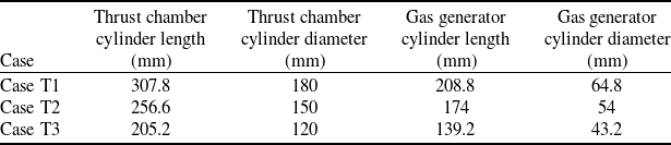
Thrust chamber parameters – structural (cylinder length and diameter) – are varied to assess their interplay with acoustic modes and stability. Nominal baselines are scaled to 120%, 100% and 80% (Table 2).
Structural parameters of the combustion component cylinder section for different cases, detailing variations in cylinder length and diameter to assess their impact on frequency response

Theoretical response of thrust chamber pressure to flow fluctuations under varying structural parameters, with frequency (Hz) on the x-axis. (a1) Oxidiser. (a2) Fuel. (a) Thrust chamber response under varying cylinder length. (b1) Oxidiser. (b2) Fuel. (b) Thrust chamber response under varying cylinder diameter.

The frequency offset patterns in the thrust chamber’s pressure response to flow fluctuations, as depicted in Fig. 11, highlight distinct trends influenced by varying structural parameters within a gas generator cycle liquid rocket engine. In Fig. 11(a), the left plot for oxidiser flow exhibits a downward shift in the primary resonant peak as cylinder length increases, while the right plot for fuel flow shows a similar downward adjustment, both reflecting the effect of extended acoustic wavelengths that reduce natural frequencies. In Fig. 11(b), the left plot for oxidiser flow displays a non-monotonic shift with diameter variation, suggesting modal compression in smaller diameters and damping in larger ones, while the right plot for fuel flow follows a comparable pattern, indicating a sensitivity to geometric changes.
Oxidiser responses across both subfigures demonstrate more pronounced frequency shifts and higher pressure-to-flow ratios compared to fuel, attributed to the oxidiser’s greater density and acoustic impedance, which enhance wave reflections. Fuel responses show a moderated amplitude sensitivity due to lower viscosity and inertial effects, revealing pathway-specific dynamic behaviours that differ between the two propellants. The variation in modal structure further underscores the influence of structural parameters on combustion stability.
These patterns carry significant implications for system stability, as longer cylinders promote low-frequency dominance that could intensify pogo oscillations, while an optimal diameter around a mid-range value balances modal confinement and damping effects. The oxidiser’s heightened sensitivity highlights the importance of tailored injector designs to address high-frequency instabilities, and the observed trends, supported by benchmark model validations, guide parametric adjustments to bolster thrust chamber performance in high-thrust applications.
The frequency offset patterns in the gas generator’s pressure response to flow fluctuations, as shown in Fig. 12. Specifically, an increase in cylinder length results in a reduction of resonant frequencies across all modes, with peaks occurring earlier in the frequency spectrum, while a decrease in cylinder diameter similarly lowers these resonant frequencies. Given that the model accounts for the acoustic characteristics of the thrust chamber, alterations in structural parameters exert a notable impact on pressure pulsations, particularly at higher frequency ranges, a trend also evident in the pressure pulsation patterns of the gas generator.
This influence becomes particularly apparent when examining the dynamic response of the combustion system. The extended cylinder length shifts the modal behaviour toward lower frequencies, compressing the spacing between resonant peaks, whereas a reduced diameter further modulates these modes by tightening their distribution. The acoustic coupling within the thrust chamber amplifies these effects, leading to significant pressure pulsation variations that are more pronounced in the higher frequency domain.
Theoretical response of gas generator pressure to flow fluctuations under varying structural parameters, with frequency (Hz) on the x-axis. (a1) Oxidiser. (a2) Fuel. (a) Gas generator response under varying cylinder length. (b1) Oxidiser. (b2) Fuel. (b) Gas generator response under varying cylinder diameter.

For instance, the pressure pulsation response of the gas generator, as illustrated in Fig. 12, demonstrates that the effects of structural parameter changes are most discernible when perturbation frequencies extend into the upper portion of the analysed frequency range. This suggests that the acoustic response of the system is highly sensitive to geometric modifications, particularly as frequencies approach the upper limits of the studied spectrum, necessitating careful consideration in design optimisation.
5.0 Conclusions
This study leverages a simulation platform to investigate three distinct forced oscillation models in liquid rocket engines: the supply system’s response to thrust chamber pressure disturbances, the combustion components’ response to fluid disturbances and the combustion components’ response to pump speed disturbances. The derived frequency response characteristics provide critical insights into combustion instability mechanisms, enhancing predictive capabilities for engine design and operational reliability.
The supply system exhibits comparable oxidiser and fuel flow pulsation amplitudes under thrust chamber pressure disturbances. Cavities within the feedlines act as effective vibration isolators, with their damping efficacy increasing at higher frequencies. This behaviour mitigates pressure oscillations, enabling engineers to optimise feedline architectures to suppress instabilities, particularly in high-performance engines where structural resonance risks are pronounced.
The thrust chamber displays distinct acoustic oscillation characteristics in the 0–2000 Hz range. Oxidiser-driven pressure pulsations dominate below 670 Hz and above 1200 Hz, driven by mixture ratio fluctuations that amplify heat release variations. This oxidiser dominance underscores its pivotal role in triggering combustion instabilities, informing injector designs tailored to attenuate resonant acoustic modes in high-thrust scenarios.
In contrast, the gas generator produces predominantly low-frequency pressure oscillations, driven by fuel disturbances, with negligible effects beyond 500 Hz. Pump speed disturbances induce stronger low-frequency responses in the gas generator, peaking at 78 Hz, compared to the thrust chamber’s acoustic peaks at 184 Hz and 1918 Hz. These differential responses highlight the need for targeted turbopump integration and vibration damping strategies to mitigate rotor-induced instabilities.
Parametric analyses reveal that extending pipeline lengths by 20% shifts resonant frequencies downward by 15%, preventing alignment with operational frequencies and enhancing system resilience. Increasing injector pressure drops by 20% (e.g., to 1.32 MPa for oxidiser) improves stability margins by 1.6%, offering passive damping. Extended thrust chamber lengths or reduced diameters lower resonant frequencies but compromise stability, necessitating geometric optimisation. These insights advance aeroacoustics and combustion dynamics, supporting safer, more efficient propulsion, particularly for reusable rockets. Future work should explore nonlinear models, incorporate vortex shedding effects, and conduct hot-fire tests to validate findings and address complex multiphysics interactions.
Competing interests
The authors declare that they have no known competing financial interests or personal relationships that could have appeared to influence the work reported in this paper.