Introduction
Recently, radio frequency identification (RFID) technology has been applied in medical management, smart shelf, intelligent packaging, and other scenarios, especially in item-level tagging applications [Reference Nikitin, Rao and Lazar1–Reference Laheurte, Protat and Louzir5]. According to the working regions of antennas, RFID applications can be divided into near-field and far-field. In far-field area, electric coupling is the main form of antennas. Antennas with high gain performance are often used to realize long reading distance. Multiband and reconfigurable far-field antennas have attracted researchers’ interest in recent years [Reference Chang, Chee, Lim and Nguyen6–Reference Yi8]. However, the position and polarization of the tags will influence the performance of far-field antennas, and the stability of the system is easily affected by the surrounding environment, such as metal objects and other stray tags. Additionally, tags will be missed due to the dense placement.
In the near-field area, antennas are required to generate strong and uniform magnetic field distribution to read tags placed densely in working regions. Magnetic coupling near-field antennas are also polarization insensitivity. The greatest challenge of near-field antennas is to control the field distribution. Because of the multi-tag environments in RFID systems, antennas without confined field distribution may detect other unwanted tags in the nearby area, and the reliability of systems is decreased [Reference Parthiban9]. Therefore, the antenna radiation field is required to concentrate evenly in near-field and attenuated rapidly in far-field. A near-field RFID antenna with a confined range and gain is found to be ideal for solving this problem.
Alternatively, one of the pursuits of the near-field RFID antennas is large size, as it is the basis for obtaining a large planar reading area. Electrically large RFID antennas have been solutions in strict near-field applications such as self-service retailing, smart buildings, and several sports events and competitions [Reference Finkenzeller10]. In these applications, antennas are required to read tags in a very large area, while a long reading distance is unnecessary. Moreover, the required interrogation zones are various in different scenarios, which demand the design of a flexible reconfigurable antenna to avoid the cost brought by the replacement and redesign of the antenna. Over the years, antennas with strong and uniform field distribution have been emphasized because of the advancement of the high reading rate of tags in a large reading area [Reference Li, Liao, Yuan and Yu11–Reference Zhu, Li, Gao and Qi17]. However, these antennas only cover a certain interrogation zone. When the application scenario changes, the antenna faces the additional cost of redesign. Some research has been investigated in Refs [Reference Yao, Liang, Yu and Chen18–Reference Huang, Wang, Zhu and Tang23] for configurable antennas. Yao et al. [Reference Yao, Liang, Yu and Chen18] proposed an expandable antenna array with strong magnetic field distribution, but the array can only be extended in one direction. A configurable antenna was presented in Ref. [Reference Daiki and Perret22]. However, most of the elements in this antenna are parasitic elements, which mean that the magnetic distribution produced by the antenna is hard to be uniform. Furthermore, the gain of the antenna is higher than 1 dBi, creating a high risk of reading tags outside.
It has been shown that the fractal structure can implement many features in antenna design, such as miniaturization, multiband, and electromagnetic bandgap (EBG) structure [Reference Huang, Shiao and Wu24–Reference Li, Wang, Jiang, Bao and He28]. In Ref. [Reference Sedghi, Naser-Moghadasi and Zarrabi26], a fractal EBG and split-ring resonator (SRR) loaded antenna was fabricated for miniaturization applications. The SRR load is also helpful for making the circular polarization. By the introduction of sunflower fractal structure, a novel multiple-input and multiple-output fractal antenna with wideband characteristics was designed in Ref. [Reference Abed27]. An antenna array based on Hilbert fractal structure was proposed in Ref. [Reference Li, Wang, Jiang, Bao and He28], but the configurable performance is excluded from consideration. However, the fractal structure has not been found to improve the uniformity of field distribution in the near-field region.
In this paper, a large compact antenna array is proposed for a configurable interrogation zone. Due to the compactness and flexibility of the plane topology structure, the antenna is configurable to achieve complex and changeable reading areas in the near-field region. Meandering the lines of the Hilbert fractal structure can generate numerous magnetic loops on the antenna, resulting in a strong magnetic field. Additionally, the traveling wave distribution makes it possible to generate a uniform magnetic field and realize a large area. Prototypes with  $1 \times 8$,
 $2 \times 4$, and
 $3 \times 3$ elements are fabricated, showing that the array antenna has the ability to provide a configurable interrogation zone. The prototypes also have the advantages of low cost and ease of assembly.
Antenna design and discussion
Antenna configuration
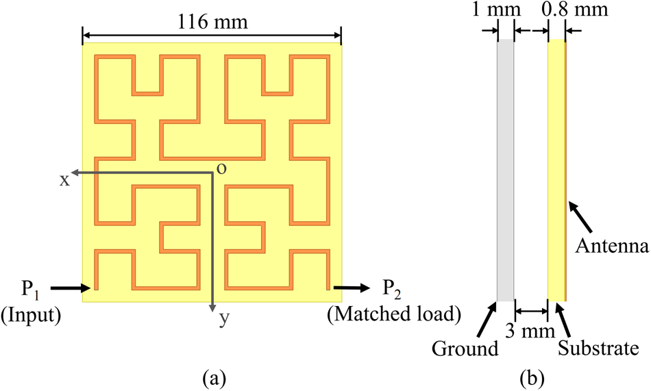
The structure of the proposed antenna element is shown in Fig. 1. The element is composed of a substrate–air–metal three-layer structure, while the antenna is printed at the top of the substrate. The substrate used here is FR4 ( $\varepsilon_{r} = 4.4$,
 $tan\sigma = 0.02$) with a thickness of 0.8 mm. The end of the element is matched. Traveling wave flows across the antenna, making sure that each part of the antenna can be excited to a strong current. To obtain a trade-off between the line spacing and the radiation field intensity, the characteristic impedance of the transmission line is set as 110 Ω. The densely distributed fractal structure contributes to the uniform magnetic field radiation, and the positions of the input and output ports allow for the flexible extension of the element. The introduction of an air layer reduces losses from the substrate and enhances the magnetic field intensity above the antenna.
Structure of the antenna element: (a) top view and (b) side view.

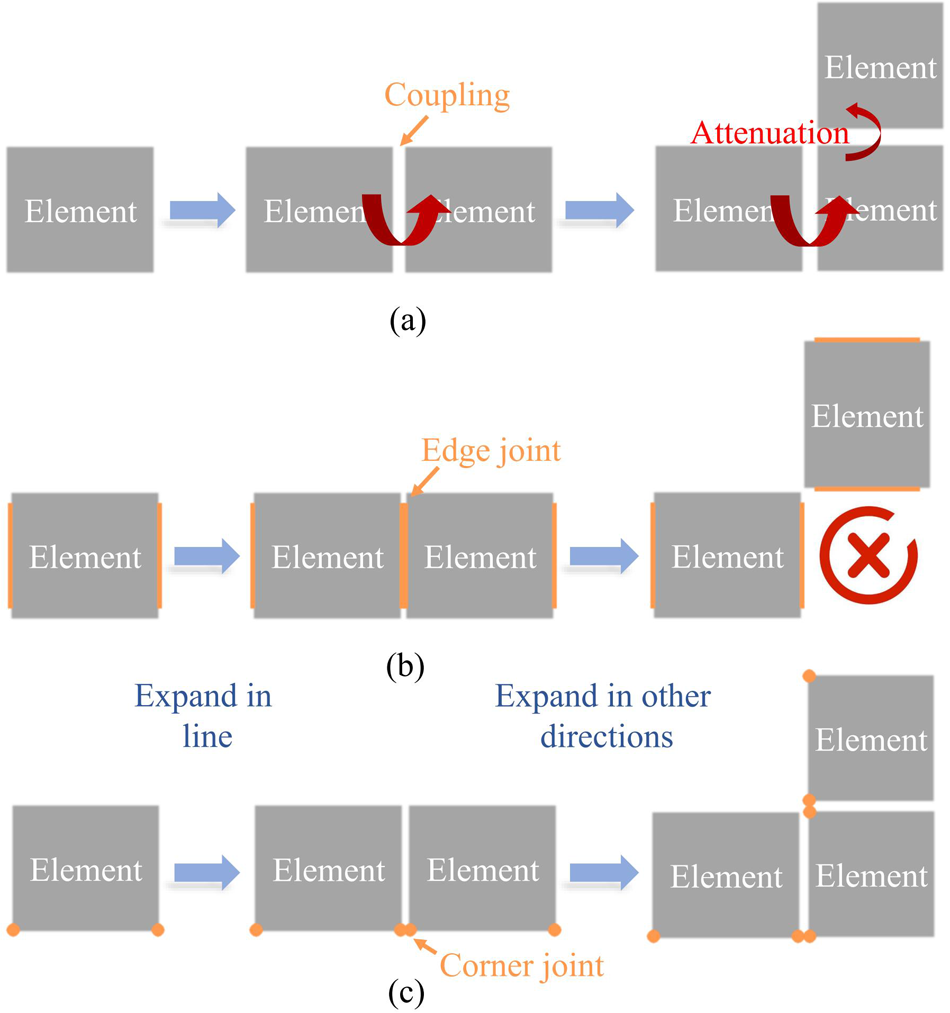
Figure 2 shows the topologies of different kinds of expandable elements. As shown in Fig. 2(a), some papers expand the antennas by coupling [Reference Wang, Xing, Guo, Li, Luo and Sim21–Reference Huang, Wang, Zhu and Tang23]. Though the relative position of the elements can be adjusted flexibly, the transfer is very inefficient. With the antenna extending, the current intensity will decay quickly. Other expandable near-field antennas are linked end-to-end in Fig. 2(b) [Reference Yao, Liang, Yu and Chen18–Reference Li, Li, Zhu, Li, Qi and Xiao20]. The adjacent elements are connected through the edge, making those antennas easy to expand in line, but those antennas cannot expand in other directions. To solve the problems, the corner joint type in Fig. 2(c) is proposed in this paper. The input and matched loaded are placed at the corner of the antenna, which makes the antenna capable of expanding freely in the plane while maintaining the compact arrangement between the elements.
Topologies of different kinds of expandable elements.

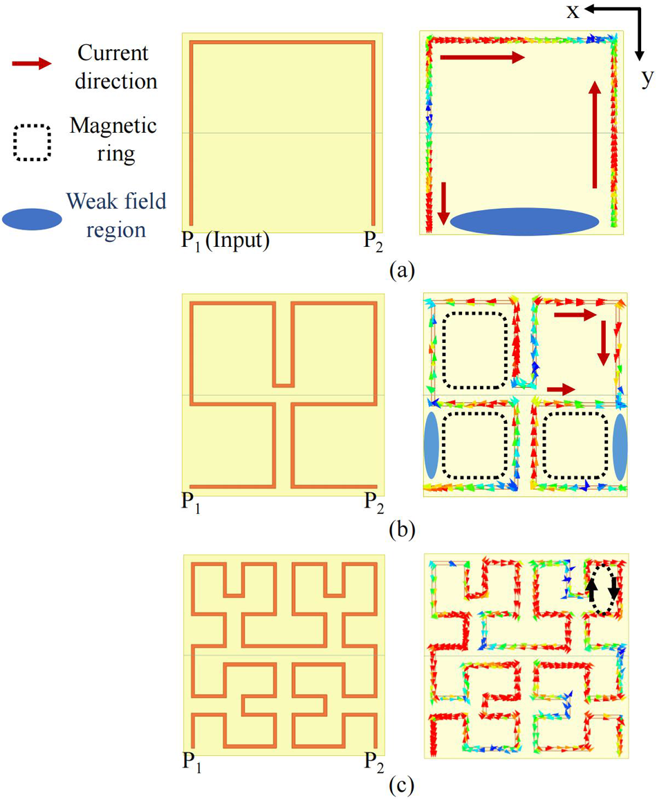
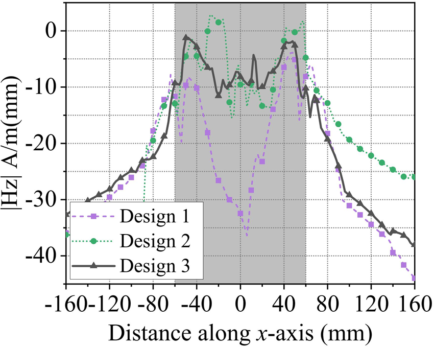
In Fig. 3(a), a square magnetic ring consisting of only three lines is the most basic structure to achieve the corner joint type. The end of the ring is matched to generate traveling wave current. However, because of the large size of the element, reverse currents occur in the antenna, resulting in a nonuniform magnetic field distribution. A weak magnetic field also appears at the open side of the square ring. Figure 4 shows that the magnetic field strength decreases rapidly at the center of the antenna. Based on the fractal theory, more and smaller rings could be designed in one element to achieve a more uniform magnetic field. Compared with the basic structure, the element with second-order fractal structure in Fig. 3(b) has a better field distribution. But the reverse currents and weak magnetic field still exist in the rings. Considering the field performance and coupling between adjacent microstrip lines, the third-order fractal structure is chosen as the element structure. In Fig. 3(c), because of the smaller size and compact distribution of the third-order fractal structure, the effects of the loops with opening are further weakened, and currents in loops become even and in phase. Though the open loop could be replaced by a smaller one or new branches, additional coupling will be introduced. The reflected currents generated by coupling may decrease the current intensity at some positions of the elements, which is not expected. Figure 4 shows the simulated  $|H_{z}|$ of the three designs along the x-direction. Results show that design 3 has a better performance of near-field magnetic field. Additionally, the results of design 3 are also much better than antennas in Refs [Reference Yao, Liang, Yu and Chen18, Reference Li, Li, Zhu, Li, Qi and Xiao20].
Evolution and surface current distribution of the proposed antennas: (a) design 1, (b) design 2, and (c) design 3.

Simulated magnetic field distribution of the three designs along x-direction at z  $= 10\ \mathrm{mm}$ at 922 MHz.

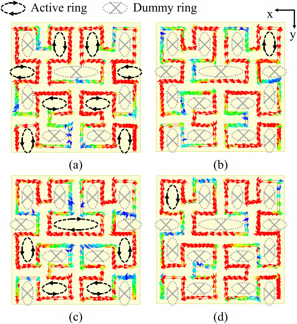
To explain the performance of the third-order fractal structure, we have simulated the current distribution of the antenna at different times, as depicted in Fig. 5. The equivalent magnetic rings are all marked in the element. It can be seen that at the phase of 30∘, the rings marked with black color are excited to generate the maximum magnetic field, which results in small, uniform magnetic field regions above the rings. Similarly, at a phase of 80∘, 120∘, and 160∘, uniform magnetic field regions are generated above other active rings. Traveling wave current distribution ensures that each ring in the antenna can be excited separately, avoiding the impact of the minimum current and reverse current. In a word, as the traveling wave current flows, the magnetic radiation units are excited in turn, ensuring a uniform magnetic field is generated in each region above the element over a whole cycle.
Surface current distribution at 922 MHz of the antenna element at a phase of (a) 30∘, (b) 80∘, (c) 120∘, and (d) 160∘.

Compared with the previous antennas, the proposed antenna array has a significant advantage of flexible and compact array design. Through the rotating and connecting of the elements, the antenna can be expanded in any direction with a compact structure and uniform magnetic field distribution.
Array design and discussion
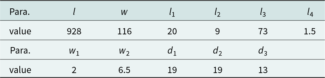
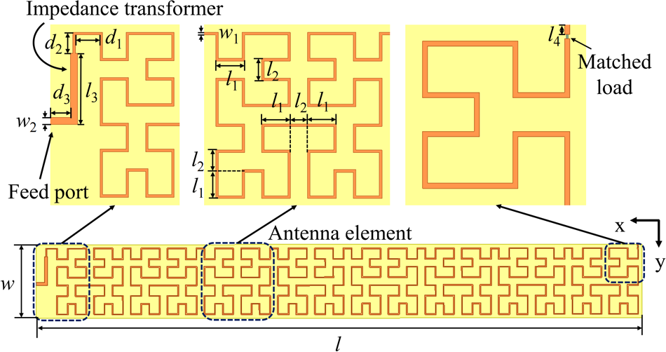
To realize a large and changeable interrogation zone, the antenna elements are connected end to end, and a matching load is set at the end of the entire antenna. A  $1 \times 8$ array prototype was designed in Fig. 6, which could be further expanded by increasing the number of elements. The optimized dimensions of the array antenna are shown in Table 1. l 2 is the distance between the major radiation loops. By adjusting the value of l 2, the coupling could be reduced. The sum of the lengths of d 3 and l 3 is 1/4λ (λ: wavelength in substrate), which means that a 1/4λ impedance transformer is introduced to transform the impedance from 110 to 50 Ω.
Optimized dimensions of the  $1 \times 8$ array antenna (unit: mm)

Configuration of the  $1 \times 8$ array antenna.

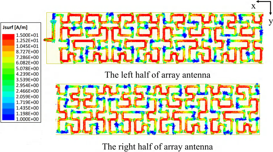
The simulated current distribution of the array antenna can be seen in Fig. 7, the current distribution on the antenna is equivalent to 8 units corresponding to a total of 152 electrical rings, which is enough to realize the recognition of all tags in the reading area.
Surface current distribution at 922 MHz of the  $1 \times 8$ array antenna.

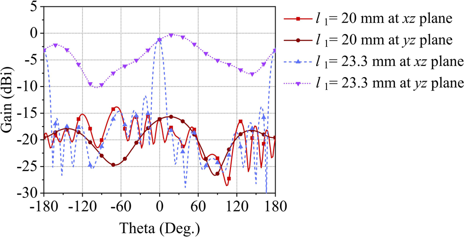
It is necessary to achieve a characteristic of low far-field gain to avoid misreading outside tags [Reference Yao, Liang, Yu and Chen29]. The current distribution between antenna elements is not in phase so that the far-field radiation of elements can cancel each other without affecting the near-field performance. Additionally, we have designed another array with in-phase fed elements. The feed between elements can be regarded as a series feed. To obtain the in-phase feeding, the length of l 1 is set to 23.3 mm so that the line length of the element is an integer multiple of the wavelength. Figure 8 shows the far-field gain of two different arrays. Though the aperture of the antenna array is very large, the far-field gain can be significantly reduced by adjusting the length of l 1. Compared with the in-phase design, the array in this paper has the effect of low far-field gain even in a large array.
Simulated far-field gain at 922 MHz of the  $1 \times 8$ array antenna of the proposed array (
 $l = 20\ \mathrm{mm}$) and another array, where elements are designed in phase (
 $l = 23.3\ \mathrm{mm}$).

Analysis of the near-field magnetic field
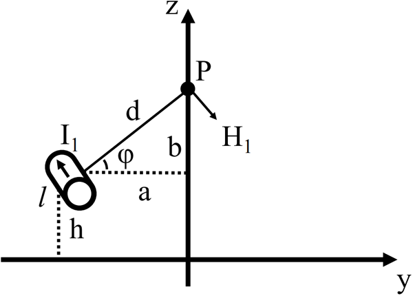
To analyze the magnetic field of the proposed antenna, a simplified structure of straight wire above the ground is first considered in Fig. 9. Because the length of the line is much shorter than λ, the current in the line can be regarded as uniform. The location of the center of the wire is (0, −a, h) in Cartesian coordinate system, while the observation point P is at 0, 0, and h + b. According to the Biot–Savart law [Reference Pozar30], the magnetic field generated by I 1 at point P can be expressed as follows:
 \begin{equation}
\boldsymbol{H} = \frac{1}{4\pi}\int_{l'}\frac{Id\boldsymbol{l'}\times\boldsymbol{R}}{R^{3}} = \frac{I_{1}}{2\pi{d}}\frac{\frac{l}{2}}{\sqrt{(\frac{l}{2})^2+d^2}}\boldsymbol{e_{\varphi}}
\end{equation}
where d is the distance between point I 1 and P. And  $\boldsymbol{e_{\varphi}}$ is the direction of the H.
Simplified model of the magnetic field generated by single long straight wire.

Therefore, the z-component of the magnetic field at point P can be concluded as follows:
 \begin{equation}
\boldsymbol{H_{z}} = -\frac{I_{1}a}{2\pi{(a^2+b^2)}}\frac{l}{\sqrt{l^2+4d^2}}\boldsymbol{e_{z}}
\end{equation}
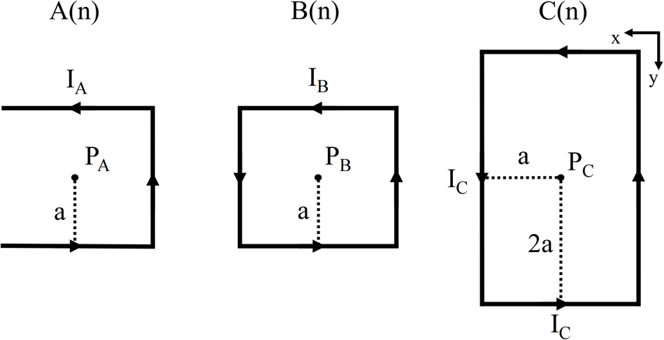
Figure 10 describes the model of the three types of magnetic radiation units, unit B(n) can be seen as a whole square magnetic ring, and the length of each wire is 2a. Compared with B(n), A(n) can be regarded as a square magnetic ring with only three sides, while C(n) is equal to a larger square magnetic ring which is twice the size of B(n). Similarly, the z-component of the total magnetic field generated by the three types of magnetic radiation units in this design could be calculated as follows:
 \begin{equation}
\begin{split}
\boldsymbol{H_{A}} = -3\times\frac{I_{A}a}{2\pi{(a^2+b^2)}}\frac{l}{\sqrt{l^2+4d^2}}\boldsymbol{e_{z}}\\= -3\times\frac{I_{A}a^2}{2\pi{(a^2+b^2)}\sqrt{2a^2+b^2}}\boldsymbol{e_{z}}
\end{split}
\end{equation}
 \begin{equation}
\boldsymbol{H_{B}} = -4\times\frac{I_{B}a^2}{2\pi{(a^2+b^2)}\sqrt{2a^2+b^2}}\boldsymbol{e_{z}}
\end{equation}
 \begin{equation}
\begin{split}
\boldsymbol{H_{C}} = -2\times\frac{I_{C}a^2}{2\pi{(a^2+b^2)}\sqrt{2a^2+b^2}}\boldsymbol{e_{z}}\\-2\times\frac{I_{C}a^2}{\pi{(a^2+b^2)}\sqrt{5a^2+b^2}}\boldsymbol{e_{z}}
\end{split}
\end{equation}
Simplified model of the magnetic field generated by three types of magnetic radiation units in the antenna.

By the superposition of the radiation wires, a strong magnetic field could be generated above the radiation units. As the height of the point increases, the magnetic field at the point weakens. In addition, in order to realize a larger interrogation zone, the flatness of the field distribution is also necessary to be focused, which is obtained by the arrangement of radiation units.
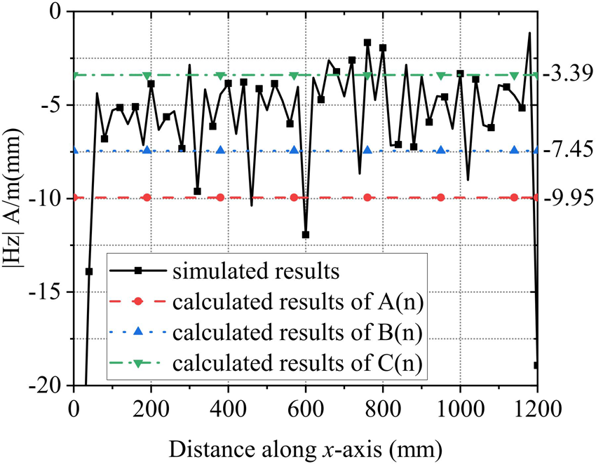
To further analyze the value of the z-component of the magnetic field, currents in the loop are considered uniform and the linear current density is approximatively set as 15 A/m. The length a in the antenna is 22 mm, and the height b is 10 mm. Then, the calculated Hz of units and the simulated result of  $1 \times 8$ array at the height of 10 mm are plotted in Fig. 11. From the calculation, unit C(n) has the strongest magnetic field distribution, while the magnetic field generated by unit A(n) is the weakest. By the superposition of the magnetic field generated by the radiation units, a strong and uniform magnetic field distribution is obtained along the x-axis from −600 to 600 mm. Due to the compact structure of the antenna, the simulated Hz curve of the antenna fluctuates roughly between the values of unit A(n) and C(n). The simulation result fits well with the calculation. Calculated results show that the proposed antenna produces a stronger magnetic field, and the flatness of field distribution can be guaranteed well. With the antenna expanding, the value of the Hz keeps stable.
Calculated and simulated magnetic field distribution at  $\mathrm{z} = 10\ \mathrm{mm}$.

 $2 \times 4$ and
$3 \times 3$ array antenna design


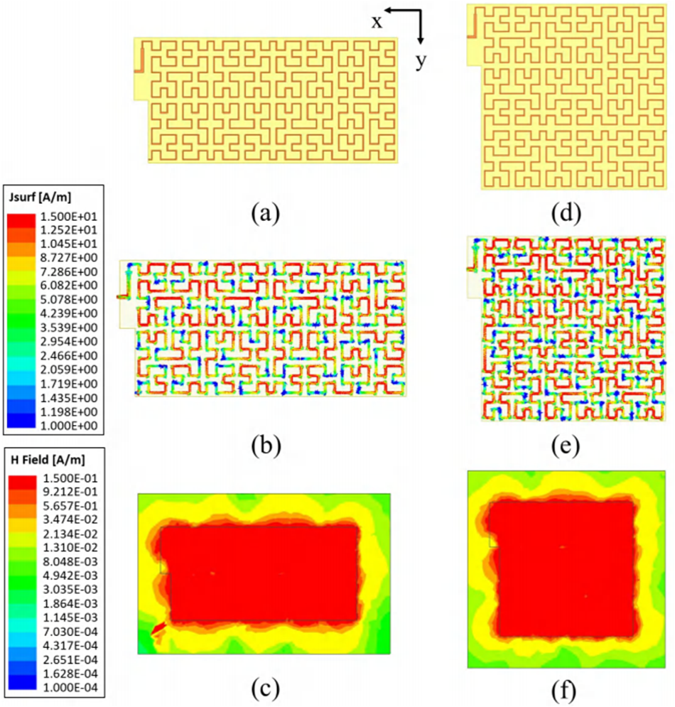
Figure 12(a) shows the structure of the proposed  $2 \times 4$ array antenna. The current distribution of this antenna can be seen in Fig. 12(b). Figure 12(c) illustrates the simulated magnetic field distribution, indicating that the
 $2 \times 4$ array antenna is capable of producing strong and uniform magnetic field distribution above the antenna surface at
 $\mathrm{z}= 20$ and 30 mm. The configuration of the
 $3 \times 3$ array antenna is shown in Fig. 12(d). As shown in Fig. 12(e), the number of the antenna elements is increased to 9, so that a larger interrogation zone is generated. Same with the antenna, the magnetic field distribution in Fig. 12(f) is changed into square, making sure tags in the reading area above antenna can be identified. Simulated results of the
 $2 \times 4$ and
 $3 \times 3$ array antennas show that the design is capable of being further extended by adding more array elements along both x- and y-directions.
The proposed  $2 \times 4$ array: (a) structure, (b) surface current distribution, and (c) magnetic field distribution at
 $\mathrm{z} = 20 \mathrm{mm}$. The proposed
 $3 \times 3$ array: (d) structure, (e) surface current distribution, and (f) magnetic field distribution at
 $\mathrm{z} = 20\ \mathrm{mm}$.

Simulated results of the  $2 \times 4$ and
 $3 \times 3$ array antennas show that the design is capable of being further extended by adding more array elements along both x- and y-directions. Additionally, By reconfiguration and extension, the designed array antenna can be used in complex application scenarios with irregularly shaped regions.
Experimental measurement results
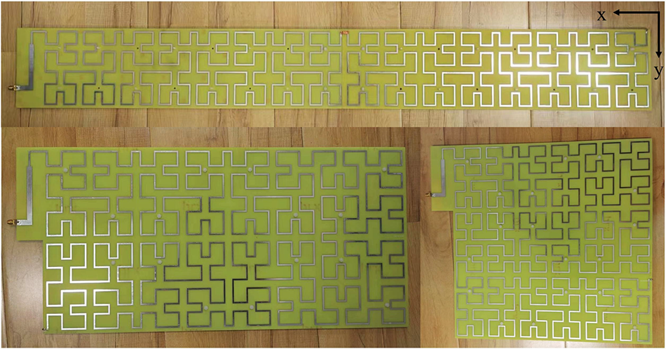
In Fig. 13, the performance of the proposed array antennas was evaluated by fabricating the  $1 \times 8$ array,
 $2 \times 4$ array, and
 $3 \times 3$ array, respectively.
Fabricated prototypes of the proposed  $1 \times 8$,
 $2 \times 4$, and
 $3 \times 3$ array antennas.

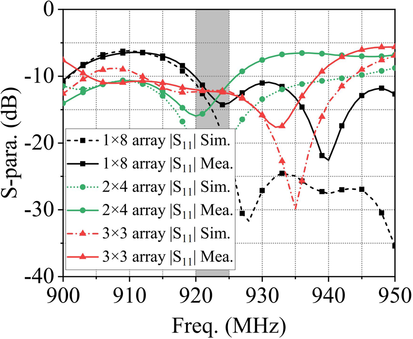
The simulated and measured reflection coefficients are shown in Fig. 14, and the Chinese standard bandwidth (920–925 MHz) can be covered by all three arrays. The antenna with different array forms has different S-parameter curves. By adjusting the 1/4λ impedance transformer in Fig. 6, any other configuration of the antenna would be confirmed to present great impedance characteristics in the band. The measured S-parameter of the  $1 \times 8$ array has significantly deteriorated. This is because the length of the antenna is greater than the maximum size of the Printed Circuit Board (PCB) process. When we splice two
 $1 \times 4$ arrays into a
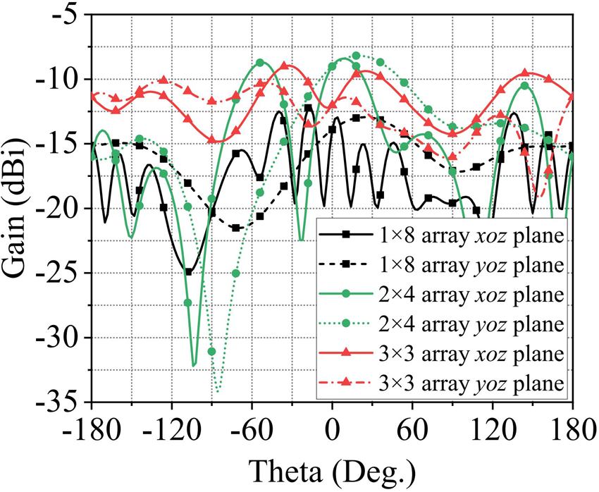
 $1 \times 8$ array, additional errors are introduced. Moreover, because of the inhomogeneity of the permittivity of the substrate and the bending of the antenna in large-size processing, the simulated and measured results of other arrays have some discrepancies. To briefly explain the far-field characteristics of the antennas, Fig. 15 shows the simulated far-field gain. The peak gains of the antennas are all below −8.6 dBi, which are significantly less than 0 dBi. Therefore, the far-field radiation is very weak though the antennas have a large size. In other words, the proposed configurable large array antennas can be considered suitable for near-field applications.
Simulated and measured reflection coefficients of the proposed  $1 \times 8$,
 $2 \times 4$, and
 $3 \times 3$ array antennas.

Simulated far-field gain of the proposed  $1 \times 8$,
 $2 \times 4$, and
 $3 \times 3$ array antennas.

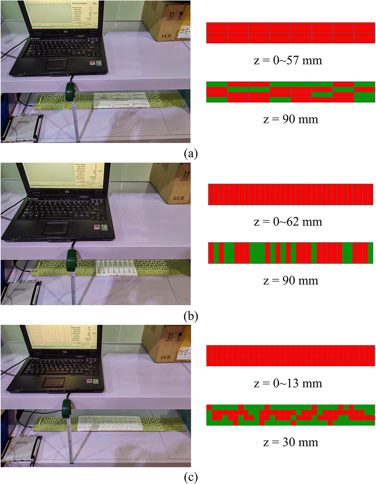
To further demonstrate the reading performance of the proposed array antennas, an Impinj R420 reader with a frequency band covering the Chinese standard was used to detect the Impinj J41 loop-like tag and Alien AZ9640 dipole-like tag. The reading rate is obtained by dividing the detected number by the total number.
Test setup and measured reading areas of the proposed  $1 \times 8$ array with (a) AZ9640 tags along x-direction, (b) AZ9640 tags along y-direction, and (c) J41 tags.

The test scene and tested reading rate of the  $1 \times 8$ array is shown in Fig. 16(a). The height of the shelf for placing the antennas is 400 mm, which is much greater than the reading distance of the antennas. And as a result, the shelf will not influence the reading performance of antennas. To test the AZ9640 tag tags, the foam sheet is divided equally into grids with a size of
 $120\, \mathrm{mm} \times\ 30\, \mathrm{mm}$, and each grid is attached to a dipole-like tag. Specifically, the foam sheet is placed at a certain distance among 0–120 mm from the antennas to test the number of detected tags. Then, the foam sheet is moved horizontally to ensure that every position of this vertical distance is tested. At each vertical distance, all the positions within the required reading area are tested by checking whether the tag here is detected by the RFID reader, and the reading rate is obtained by dividing the detected number by the total number. The test scene for dipole-like tag polarization parallel to the y-direction are shown in Fig. 16(b). The foam sheet is divided equally into grids with a size of
 $30\, \mathrm{mm} \times\ 30\, \mathrm{mm}$ to cover the loop-like tag, which is shown in Fig. 16(c).
Figure 16 also shows the measured reading areas of loop-like and dipole-like tags along x- and y-directions at different distances from the  $1 \times 8$ array antenna. The active areas are marked by red and the undetected areas are marked by green. The reading area of the
 $1 \times 8$ array is
 $960\, \mathrm{mm} \times 120\, \mathrm{mm}$. The reading distance of the loop-like tag, dipole-like tag along x- and y-directions is 13, 57, and 62 mm.
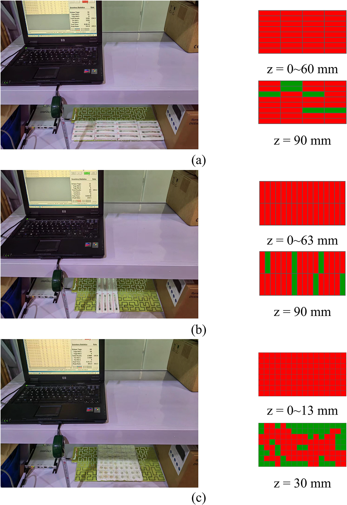
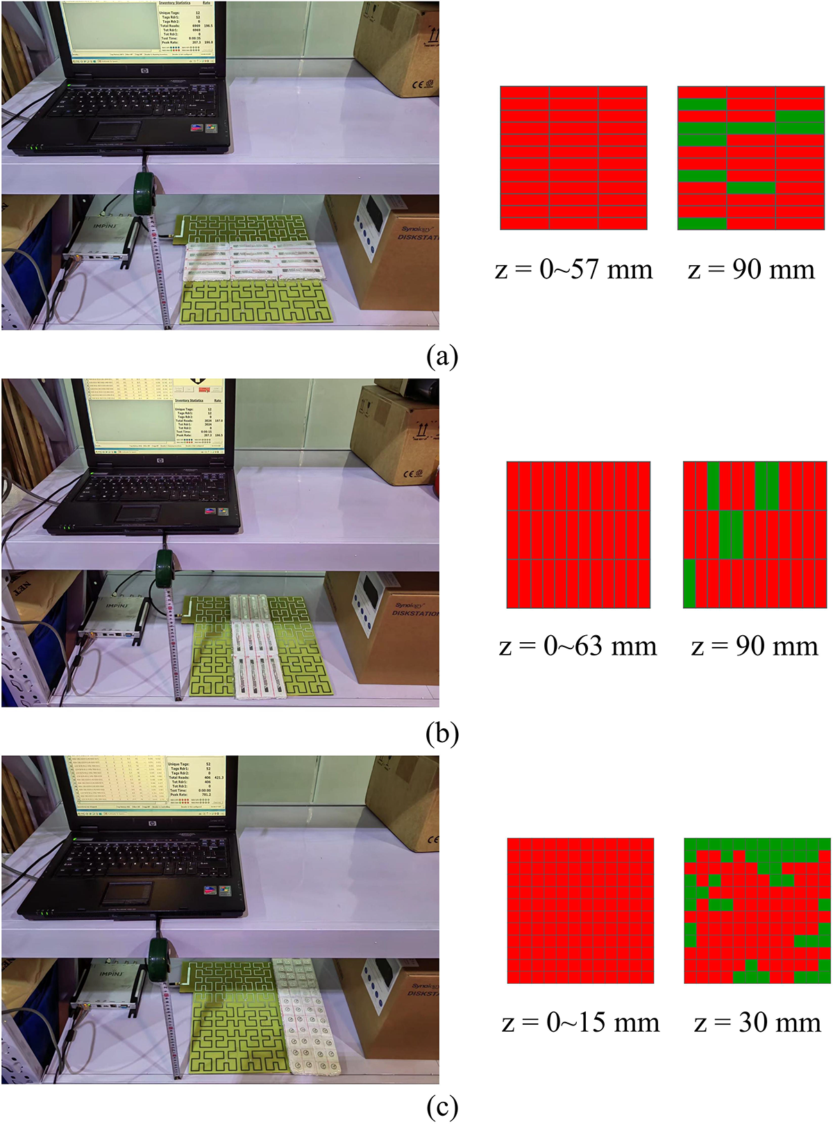
The test scene and reading areas of the  $2 \times 4$ array and
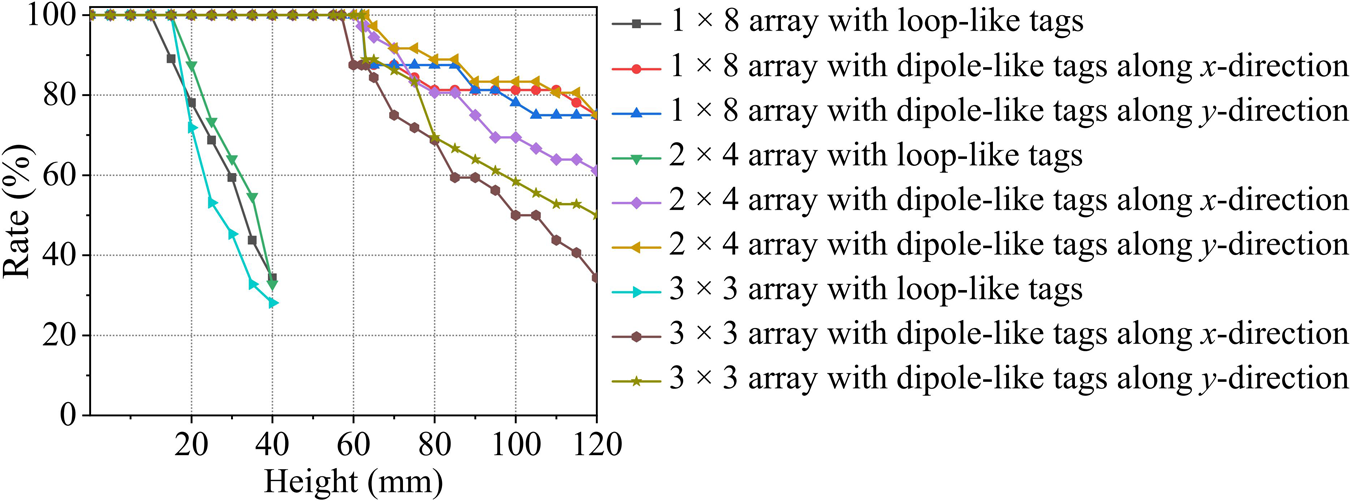
 $3 \times 3$ array are shown in Figs. 17 and 18, respectively. Additionally, Fig. 19 illustrates the reading rate of the proposed
 $1 \times 8$,
 $2 \times 4$, and
 $3 \times 3$ array antennas, the reading rates of antennas are defined as
 \begin{equation}
\eta(h) = \frac{n_{active}(h)}{n_{total}}
\end{equation}
Test setup and measured reading areas of the proposed  $2 \times 4$ array with (a) AZ9640 tags along x-direction, (b) AZ9640 tags along y-direction, and (c) J41 tags.

Test setup and measured reading areas of the proposed  $3 \times 3$ array with (a) AZ9640 tags along x-direction, (b) AZ9640 tags along y-direction, and (c) J41 tags.

Reading rate of the proposed  $1 \times 8$,
 $2 \times 4$, and
 $3 \times 3$ array antennas.

where  ${n_{active}}$ refers to the activated tags at a certain height, while
 ${n_{total}}$ refers to the total tags at a certain height. h is the test height. Take the dipole-like tags as examples, the
 ${n_{total}}$ is 32 for the test of
 $1 \times 8$ and
 $2 \times 4$ arrays, and 36 for the test of
 $3 \times 3$ array. Results show that the proposed configurable array antennas can achieve stable read performance in different antenna shapes and different reading areas.
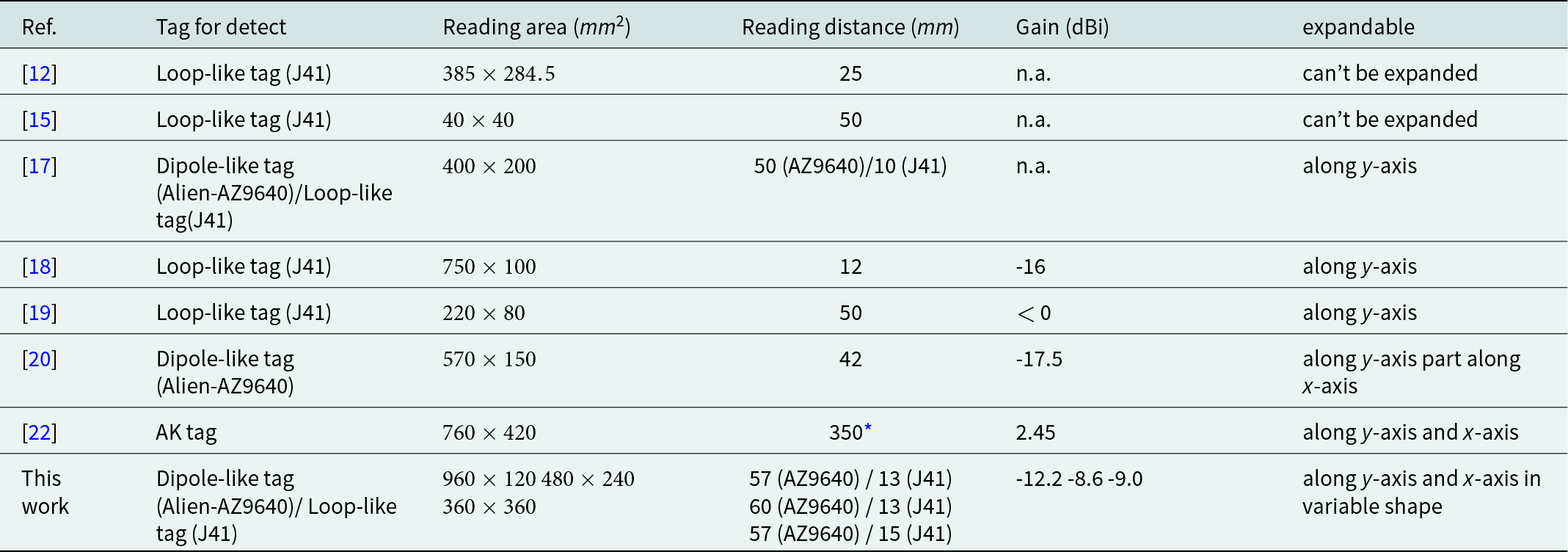
In Table 2, the key data of the proposed array antennas are compared with the near-field antennas proposed in the literature. It can be seen that the traditional near-field antenna in Refs [Reference Wasfy and Hammad12, Reference Kim, Ahn and Lee15] is hard to be expanded and has a small reading area. Antennas in Refs. [Reference Zhu, Li, Gao and Qi17–Reference Xing, Li, Sim, Li and Li19] preliminarily realize the expandability, but they can be only expanded along one direction. Antenna in Ref. [Reference Li, Li, Zhu, Li, Qi and Xiao20] shows good performance in the reading area. But the proposed antennas exhibit better reading and expanding performance. The study [Reference Daiki and Perret22] has a long reading distance; however, the far-field gain of the antenna is close to that of far-field antennas, which will greatly restrict the applications of the antenna. What is more, the proposed antennas can be expanded in variable shape. To summarize, on the premise of meeting the demand of reading distance and low far-field gain, the proposed antenna arrays feature the advantages of a large reading area and good expandability performance.
Comparison with reported near-field antennas

* Reading distance when 70% of the tags are detected.
Real testing with assets and discussion
In this section, the effect of adjacent assets on antenna impedance matching sensitivity is tested and discussed. In real life, a radome is placed above the antenna, and the tagged assets are placed at different positions above the radome. For instance, in retail checkout counters, a polystyrene sheet is used as antenna radome because that the dielectric constant of it is similar to the air, and it has a mininal influence on the antenna performance. However, the mediums of common assets are various according to the type of assets. When the mediums of assets are proximity to the antenna, the characteristic of antenna will be affected. Compared to lighter mediums, electromagnetic waves travel slower in denser mediums, resulting in detuning effect.
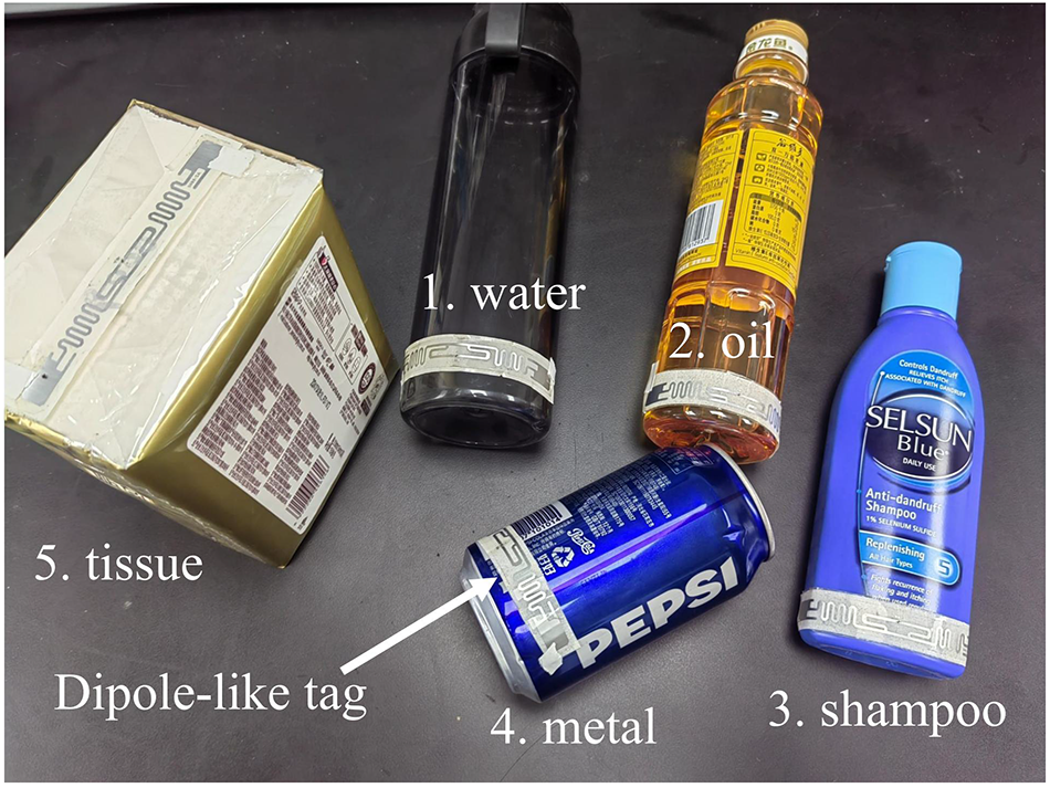
To verify the effect of different assets on antenna return loss, five different assets including water, oil, shampoo, metal can, and tissue are used for testing in Fig. 20. Tags are attached on the lower part of the assets’ surface so that the tags are closer to the antenna. The performance of dipole-like tag is varied because different mediums offer different attenuations.
Assets attached with tags. (1) Water, (2) oil, (3) shampoo, (4) metal can, and (5) tissue.

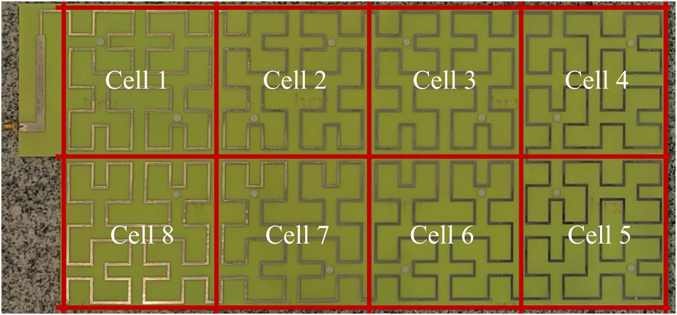
The reader antenna’s reflection coefficient is tested by placing different assets on the surface of  $2 \times 4$ array because it has the worst return loss performance, and the antenna radome is approximated by a 5 mm foam. Considering the size of assets, the antenna is divided into eight cells and each cell has a size of
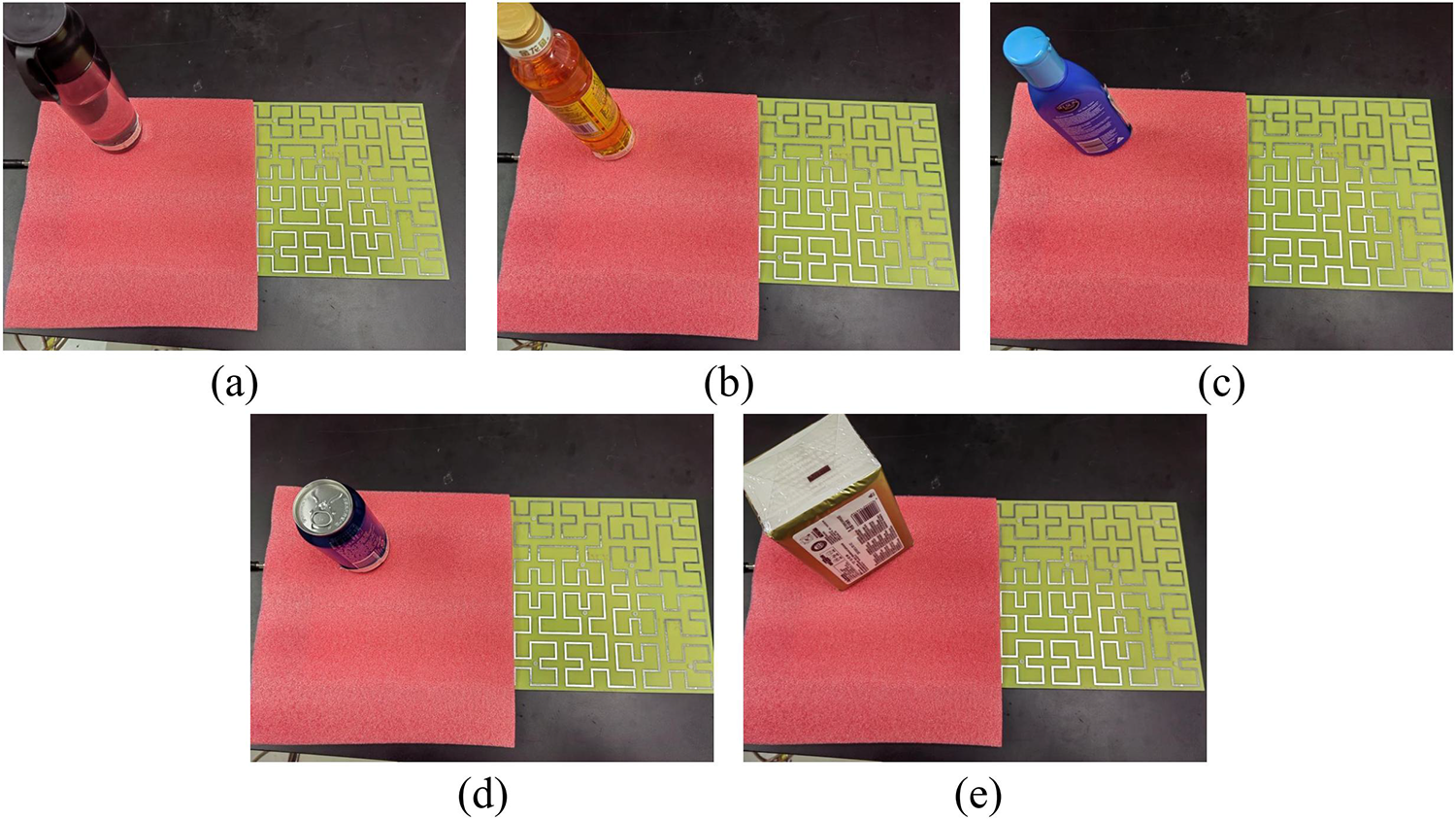
 $120\, \mathrm{mm} \times 120\, \mathrm{mm}$, so that the assets can fit into the cell, which is shown in Fig. 21. For each asset placed in each cell, the reflection coefficient of the antenna is tested to evaluate trends in the impact of assets on antenna performance. The setup of assets in cell 1 is illustrated in Fig. 22.
Test cells of the  $2 \times 4$ array.

The setup of assets placed in cell 1. (a) Water, (b) oil, (c) shampoo, (d) metal can, and (e) tissue.

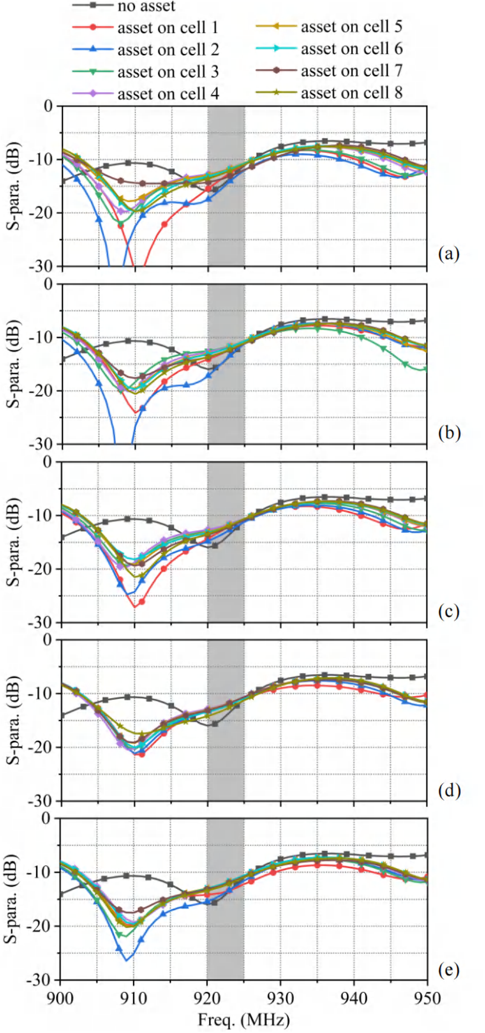
The antenna’s reflection coefficient for each asset in each test cell is given in Fig. 23. For water and oil assets, the reflection coefficient has deteriorated slightly at the ultra-high-frequency (UHF) band, and a strong resonance is generated between 900 and 910 MHz. For shampoo and metal assets, the resonant frequency of the antenna is concentrated near 910 MHz. Similar results are found when the antenna is placed with tissue. From the aspect of different cells, when assets are placed on cells 1, 2, 7, and 8, the antenna is more likely to have a better reflection coefficient at the UHF band. Therefore, when used under the shelf, the assets are suggested to be placed near the feed port and end of the antenna.
The effect of assets on different cells. (a) Water, (b) oil, (c) shampoo, (d) metal can, and (e) tissue.

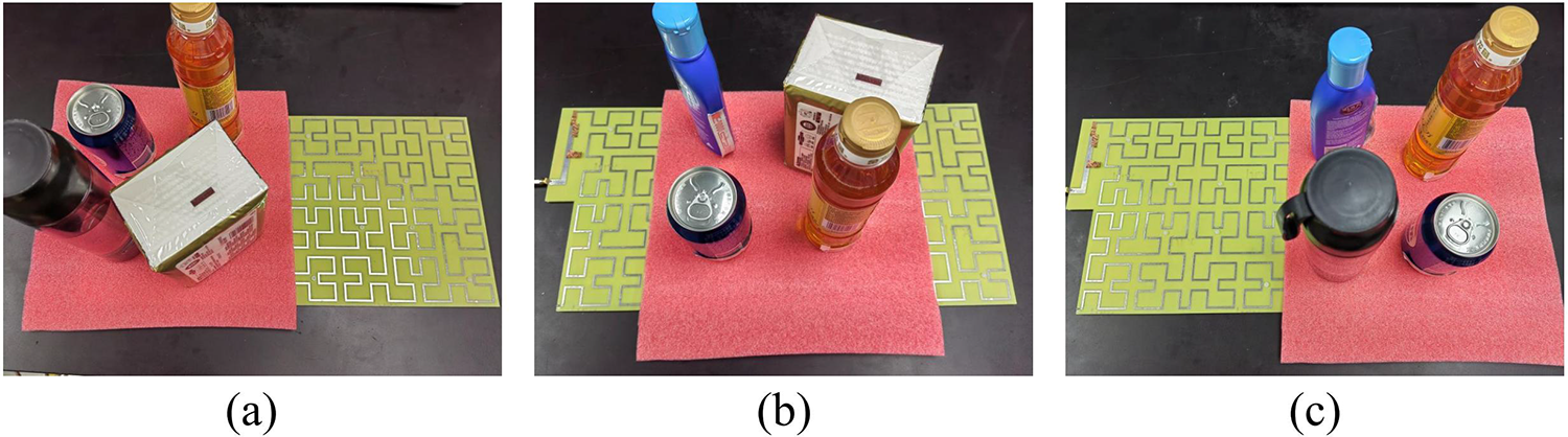
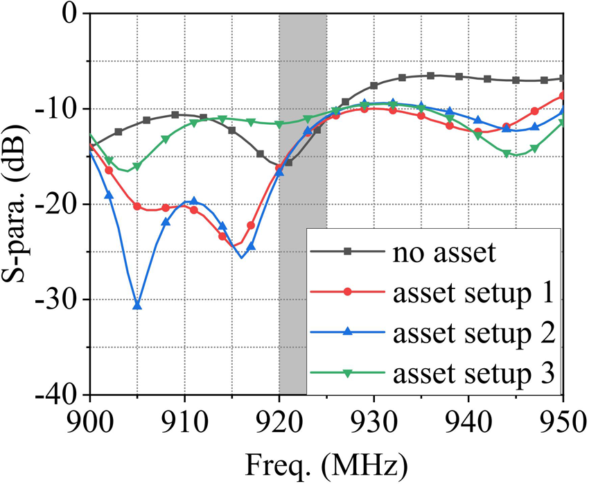
To fully test the effects of the assets on the antenna, three setups of assets on the antenna are tested in Fig. 24. In setup 1, the water, oil, metal, and tissue assets are placed on cells 1, 2, 7, and 8. In setup 2, the oil, shampoo, metal, and tissue assets are placed on cells 2, 3, 6, and 7. The tested results are shown in Fig. 25. Though the resonant frequency and resonant depth of the antenna are affected by the asset, the operating bandwidth of the antenna is still able to cover the Chinese UHF band.
The setup of antenna array with several assets placed. (a) Setup 1, (b) setup 2, and (c) setup 3.

The effect of assets. (a) Setup 1, (b) setup 2, and (c) setup 3.

Conclusion
The working principle, simulation, and measurement results of the proposed novel expandable traveling wave antenna are presented in this paper. The antenna has shown the capability of generating strong and uniform magnetic field distribution in a large and configurable region above the antenna. As a proof of concept, antenna prototypes with the  $1 \times 8$,
 $2 \times 4$, and
 $3~\times~\, \mathrm{3}$ elements have been tested. Results have shown that the prototypes have a larger reading area and better extension features compared with other reported antennas. The near-field reader antenna proposed in this paper provides a wide range of RFID applications that can be expected to be applied to increasingly complex scenarios.
Acknowledgements
This work was supported by the project of 62321001 from the Science Fund for Creative Research Groups of the National Natural Science Foundation of China (NSFC).
Competing interests
The author(s) declare none.

Yaohui Niu received the B.E. degree from Beijing University of Posts and Telecommunications, Beijing, China, in 2018, where he is currently pursuing the Ph.D. degree with the School of Electronic Engineering. His current research interests include RFID antennas, millimeter-wave antennas, phased array and metasurface antennas.

Xiuping Li received the B.S. degree from Shandong University in 1996, the Ph.D. degree from Beijing Institute of Technology in 2001. From 2001 to 2003, she joined in Positioning and Wireless Technology Center, Nanyang Technological University in Singapore, where she was a research fellow and involved in the research and development of the RFID system. In 2003, she was a research professor in Yonsei University, Seoul, South Korea. Since 2004, she joined Beijing University of Posts and Telecommunications as Associate Professor and promoted to Professor in 2009. She has been selected into the New Century Excellent Talents Support Plan in National Ministry of Education, the Beijing Science and Technology Nova Support Plan, in 2007 and 2008, respectively. She won the second prize of the Progress in Science and Technology of China Institute of Communications and the Excellent Achievements in Scientific Research of Colleges and Universities in 2015 and 2018, respectively. She is the author of 4 books, over 200 journal and conference papers. She is also awarded more than 30 PRC patents. Her current research interests include millimeter-wave antennas, THz antennas, RFID systems, and Monolithic Microwave Integrated Circuit (MMIC) design.

Wenyu Zhao received the B.S. degree and Ph.D. degree from the Beijing University of Posts and Telecommunications, Beijing, China, in 2018 and 2023, respectively. He is currently a Postdoctoral Researcher with the School of Electronic Engineering and the Beijing Key Laboratory of Work Safety Intelligent Monitoring in the Beijing University of Posts and Telecommunications. His current research interests include high-order-mode antennas, millimeter-wave antennas, and metasurface antennas.

Zihang Qi received the B.E. degree in electronic and information engineering from China Three Gorges University, Yichang, China, in 2013, and the Ph.D. degree in electronic science and technology from Beijing University of Posts and Telecommunications, Beijing, China, in 2019. He is currently an Associate Research Fellow with Beijing University of Posts and Telecommunications. His current research interests include orbital angular momentum antennas, millimeterwave/terahertz antennas, and microwave filters.