1. Introduction
Droplet impacts are essential in very different contexts from industrial applications such as ink-jet printing, additive manufacturing or atomisation of liquid jets to environmental situations such as soil erosion by rain. The drops can impact a solid surface (Josserand & Thoroddsen Reference Josserand and Thoroddsen2016), a thin liquid film (Josserand & Zaleski Reference Josserand and Zaleski2003; Yarin Reference Yarin2006) or a deep liquid pool (Duchemin et al. Reference Duchemin, Popinet, Josserand and Zaleski2002; Michon et al. Reference Michon, Josserand and Séon2017).
Although the dynamics of the impacts depends strongly on the impacted substrate, all cases exhibit similar general trends, for instance, spreading at low impact velocity and splashing at high impact velocity. Another feature seen in drop impact is the entrapment of an air pocket at the moment when the drop touches the substrate (Thoroddsen et al. Reference Thoroddsen, Etoh and Takehara2003, Reference Thoroddsen, Etoh, Takehara, Ootsuka and Hatsuki2005), giving birth to a bubble. This bubble entrapment is due to an increase of the pressure in the thin air layer located between the drop and the surface prior to impact because of viscous cushioning (Korobkin et al. Reference Korobkin, Ellis and Smith2008; Mandre et al. Reference Mandre, Mani and Brenner2009; Duchemin & Josserand Reference Duchemin and Josserand2010; Hicks & Purvis Reference Hicks and Purvis2011). It has been characterised experimentally (Thoroddsen et al. Reference Thoroddsen, Etoh, Takehara, Ootsuka and Hatsuki2005; Veen et al. Reference Veen, Tran, Lohse and Sun2012; Thoraval et al. Reference Thoraval, Takehara, Etoh and Thoroddsen2013), theoretically and numerically (Mandre et al. Reference Mandre, Mani and Brenner2009; Hicks & Purvis Reference Hicks and Purvis2011; Duchemin & Josserand Reference Duchemin and Josserand2012; Jian et al. Reference Jian, Channa, Kherbeche, Chizari, Thoroddsen and Thoraval2020) for impact onto solid surfaces or when a drop impacts the surface of the same liquid. Because the air-layer cushioning follows a lubrication dynamics, the bubble geometry can be simply described by the Stokes number, defined here using the drop diameter
 $2R_0$
, and as the ratio between the gas viscous force with the drop inertia
 $St= {\mu _{g}}/{2\rho _{l}U_{0}{R_0}}$
,
 $\rho _l$
being the drop liquid density,
 $U_0$
its impacting velocity and
 $\mu _{g}$
the viscosity of the gas (Korobkin et al. Reference Korobkin, Ellis and Smith2008; Mandre et al. Reference Mandre, Mani and Brenner2009; Duchemin & Josserand Reference Duchemin and Josserand2012; Klaseboer et al. Reference Klaseboer, Manica and Chan2014). Then balancing the drop inertia with the gas lubrication in the short time of impact, one can obtain scaling laws for bubble entrapment (Korobkin et al. Reference Korobkin, Ellis and Smith2008; Mandre et al. Reference Mandre, Mani and Brenner2009; Bouwhuis et al. Reference Bouwhuis, van der Veen, Tran, Keij, Winkels, Peters, van der Meer, Sun, Snoeijer and Lohse2012; Duchemin & Josserand Reference Duchemin and Josserand2010): the dimensionless impact time and the thickness of the entrapped gas disc scale with
 $St^{2/3}$
, while the dimensionless radius follows a
 $St^{1/3}$
law.
After its formation, the entrapped bubble usually reaches the free surface where it breaks, ejecting small micro-droplets. Understanding the bubble entrapment mechanism and its rupture is thus crucial, for instance, for printing in order to control side ejections or in aeronautics for de-icing film protection (Yamazaki et al. Reference Yamazaki, Jemcov and Sakaue2021).
In this latter case, a droplet of water impacts a film of another liquid (typically glycol) and the two liquids are usually immiscible. For when bubble entrapment involves three fluids, its formation is related to the formation of a triple point between these three fluids. While bubble formation with two fluids (air and drop on solid or same liquid substrate) has been largely studied, bubble formation and dynamics when three fluids (air, drop and film liquid) are involved remains largely unexplored, despite its importance in many different situations, from emulsions in the food industry to geophysical flows (Yeganehdoust et al. Reference Yeganehdoust, Attarzadeh, Karimfazli and Dolatabadi2020; Alventosa et al. Reference Alventosa, Cimpeanu and Harris2022). When drop impact is considered and the two fluids are immiscible, the transition between rebound and coalescence differs (Pan et al. Reference Pan, Tseng, Chen, Huang, Wang and Lai2016; Yeganehdoust et al. Reference Yeganehdoust, Attarzadeh, Karimfazli and Dolatabadi2020; Huang & Pan Reference Huang and Pan2021), while one can also question the general features of splash formation (Marcotte et al. Reference Marcotte, Michon, Séon and Josserand2019). The aim of this paper is thus to characterise numerically how the bubble entrapment (dynamics and geometry) is influenced by the presence of a thin film of dissimilar liquid. We take advantage of the free Basilisk software (Popinet Reference Popinet2009) that we adapted to model three immiscible (denoted later as air, water and oil) fluids using three volume-of-fluid functions.
In fact, three-fluid numerical simulations have been the subject of a few recent studies, e.g. drop impacts on deep pools (Hendrix et al. Reference Hendrix, Bouwhuis, van der Meer, Lohse and Snoeijer2016; Fudge et al. Reference Fudge, Cimpeanu and Castrejón-Pita2021; Sykes et al. Reference Sykes, Cimpeanu, Fudge, Castrejón-Pita and Castrejón-Pita2023), and phase change and atomisation (Dritselis & Karapetsas Reference Dritselis and Karapetsas2022; McGinn et al. Reference McGinn, Tretola and Vogiatzaki2022; Yakush et al. Reference Yakush, Sivakov, Melikhov and Melikhov2024) in particular. For the numerical method itself, the main challenge lies in the determination of the correct surface tension terms (Zhao et al. Reference Zhao, Maarek, Taleghani and Zaleski2024; Kromer et al. Reference Kromer, Potyka, Schulte and Bothe2023). This issue has been addressed with various platforms differently, for instance OpenFoam (Dritselis & Karapetsas Reference Dritselis and Karapetsas2022; McGinn et al. Reference McGinn, Tretola and Vogiatzaki2022; Yakush et al. Reference Yakush, Sivakov, Melikhov and Melikhov2024) or using level-set modelling (Zhao et al. Reference Zhao, Mao, Bai, Liu, Li and Williams2016; Yap et al. Reference Yap, Li, Lou, Pan and Shang2017). Nevertheless to the best of our knowledge, we are aware of only a few studies of drop impact on a thin film of another liquid (Chen et al. Reference Chen, Chen and Amirfazli2017; Che & Matar Reference Che and Matar2018; Qin et al. Reference Qin, Wu, Cai, Lin and You2023; Sanjay et al. Reference Sanjay, Lakshman, Chantelot, Snoeijer and Lohse2023; Fudge et al. Reference Fudge, Cimpeanu and Castrejón-Pita2024). Finally, in the present paper, we focus on the birth of the bubble, therefore just prior to the formation of the triple point (so that the no triple-line dynamics has to be considered), and propose a model for the bubble entrapment in this configuration.
2. General problem statement and numerical method
As shown in figure 1(a), a drop of diameter
 $D_0=2R_0$
, typically made of water, characterised by
 $\rho _w$
and
 $\mu _w$
as its density and dynamic viscosity, respectively, impacts a solid substrate or a thin film of thickness
 $h_0$
at velocity
 $U_0$
; the oil film is characterised similarly by
 $\rho _o$
and
 $\mu _o$
. The density and dynamic viscosity of the surrounding air are denoted
 $\rho _g$
and
 $\mu _g$
. The surface tensions associated with the different interfaces are
 $\sigma _{wg}$
,
 $\sigma _{wo}$
and
 $\sigma _{og}$
(subscripts o, g and w refer to oil, gas and water interfaces) for impact on a solid substrate, simplifying into one surface tension
 $\sigma _{wg}$
and the (static) contact angle
 $\theta$
through application of the Young equation.
(a) Impact geometry with the different parameters of interest. (b) Graphical description of the deformed droplet prior to contact, illustrating the different measured quantities of interest: the thickness of the gas layer under the centre of the droplet
 $h_{d}$
, the minimal distance between the droplet and the substrate
 $h_{min}$
and the radius of the dimple
 $r_{d}$
. Right and left parts of (b) indicate the difference between the impact on solid or liquid substrate with the introduction of
 $\delta \epsilon$
to describe the deformation of the oil film.

2.1. Physical variables and dimensional analysis
Drop impact onto a surface depends a priori on many different parameters (drop diameter and velocity, the properties of the fluids and their interface, the oil film thickness and gravity), leading to numerous dimensionless numbers. The two important dimensionless numbers that describe the dynamic features of the impact (therefore based on the drop velocity) are the Reynolds number and the Weber number (based on the liquid drop and the gas–liquid interface), which balance the inertia with the viscous and capillary effects, respectively, and are given as
 \begin{align} Re= \frac {2\rho _w R_0 U_0}{\mu _w} \;\; \quad \mbox{and} \quad \;\; We= \frac {2\rho _w R_0 U_0^2}{\sigma _{wg}}. \end{align}
Alternatively, one can use the Ohnsesorge number, which does not involve the velocity, as one of the above numbers:
 \begin{align} Oh= \frac {\mu _w}{\sqrt {2\rho _w R_0 \sigma _{wg}}}. \end{align}
The gravity effect can be quantified using the Bond number:
 \begin{align} Bo=\frac {2gR_0}{U_0^2}. \end{align}
For millimetric droplets impacting at metres per second speed, the Bond number remains of the order of or below
 $10^{-2}$
, indicating that gravity can be neglected during the impact. Therefore, although it is important to accelerate the drop before the impact, gravity will be neglected for the impact process analysis.
In the present study we assume that the dynamics is incompressible. In fact, while the Mach numbers in both liquids are small so that compressibility can be safely neglected in the liquids, the situation is more complex in the lubrication gas layer, as investigated by Mandre et al. (Reference Mandre, Mani and Brenner2009). There, they have shown that compressible effects become relevant when the dimensionless number
 $\epsilon = {P_0}/{(\rho _w^4R_0U_0^7\mu _g^{-1})^{1/3}}$
, where
 $P_0$
is the ambient pressure, is small (
 $\epsilon \ll 1$
). For the typical values of the physical parameters used in our paper,
 $\epsilon \sim 5$
for
 $U_0= 1 \textrm { m} \textrm { s}^{-1}$
and goes down to
 $0.12$
for the highest velocities studied. Notice that we are using a more viscous (10 times) gas than air. It does not change qualitatively our results but allows for more reasonable time calculations. There, the compressibility lowers the height of the bubble entrapment by a factor of 2 at most. Therefore, even if compressibility might affect our results for the highest velocities investigated, it can be safely neglected for most of our study. Furthermore, the goal of our paper is to investigate and quantify the effect of the oil layer for incompressible dynamics, and the additional effect of the compressibility should be the subject of future studies. Depending on whether the impact is on a solid or an oil film, several additional dimensionless numbers can be obtained by considering ratios between the different fluids physical properties or geometrical quantities, such as
 \begin{equation} \theta, \;\; \frac {h_0}{R_0}, \;\; \frac {\mu _g}{\mu _w}, \;\; \frac {\mu _o}{\mu _w}, \;\; \frac {\rho _g}{\rho _w}, \;\; \frac {\rho _o}{\rho _w}, \;\; \frac {\sigma _{wo}}{\sigma _{wg}} \;\; \quad \mbox{and} \quad \;\; \frac {\sigma _{og}}{\sigma _{wg}}. \end{equation}
Whereas the parameters in (2.4) may have some influence on the dynamics of drop impact, a systematic study varying all these parameters is out of the scope of this paper. Instead, we focus on the difference between impacts on a solid substrate and impacts on thin oil films (thus for small ratio
 $ {h_0}/{D_0}$
), varying primarily the impact velocity and the oil viscosity. It is important to emphasise that for impacts on solid substrates or thin films of the same fluid, it has been shown that the dynamics at short time (that of interest for us) is controlled mostly by the air cushioning through the Stokes number defined by
 \begin{equation} St=\frac {\mu _{g}}{2\rho _{w}U_0R_0}, \end{equation}
with a small dependence on the surface tension (Klaseboer et al. Reference Klaseboer, Manica and Chan2014). The aim of the present paper is thus to investigate and characterise how the oil film influences this short-time dynamics through bubble entrapment.
2.2. Numerical method
An innovative three-fluid volume-of-fluid (VOF) method was developed in the framework of the Basilisk software (Popinet Reference Popinet2009). The one-fluid formulation of the incompressible Navier–Stokes equation was adapted to describe the three-fluid system (Tryggvason et al. Reference Tryggvason, Scardovelli and Zaleski2011):
 \begin{equation} \begin{cases} \rho ^{*}\left (\frac {\partial \boldsymbol {u}}{\partial t}+(\boldsymbol {u}\cdot\nabla)\boldsymbol {u} \right)=-\nabla P + \nabla \cdot(\mu ^{*}\nabla \boldsymbol {u})+\sigma ^{*} \kappa \delta _{s} \boldsymbol {n},\\ \nabla \cdot\boldsymbol {u}=0,\\ \end{cases} \end{equation}
where
 $\rho ^{*}$
and
 $\mu ^{*}$
are constant domain functions accounting for the values of the densities and viscosities in each fluid. The Dirac function
 $\delta _{s}$
, the curvature
 $\kappa$
and the normal
 $ \boldsymbol {n}$
are defined on the interfaces, while
 $\sigma ^{*}$
is also a constant by a domain function adapted for the interfaces. The parameters
 $\rho ^{*}$
,
 $\mu ^{*}$
and
 $\sigma ^{*}$
are defined using three characteristic functions
 $\chi _w$
,
 $\chi _g$
and
 $\chi _o$
whose value is one in the associated domains (
 $w$
,
 $g$
and
 $o$
) and zero otherwise, such that one can define
 \begin{equation} \rho ^{*}=\rho _w \chi _w+\rho _g \chi _g+\rho _o \chi _o \,\, \quad \mbox{and} \quad \,\, \mu ^*=\mu _w \chi _w+\mu _g \chi _g+\mu _o \chi _o. \end{equation}
It is important to note that in this approach, each physical interface (say
 $wg$
) corresponds to the jump of two characteristic functions (
 $\chi _w$
and
 $\chi _g$
). A surface tension
 $\sigma _j$
with
 $j={w,g,o}$
is associated with each characteristic function, which can then be easily related to the physical surface tensions through the relation
 \begin{equation} \begin{cases} \sigma _{w}=\frac {1}{2}(\sigma _{wo}+\sigma _{wg}-\sigma _{og}),\\ \sigma _{g}=\frac {1}{2}(\sigma _{wg}+\sigma _{og}-\sigma _{wo}),\\ \sigma _{o}=\frac {1}{2}(\sigma _{og}+\sigma _{wo}-\sigma _{wg}).\\ \end{cases} \end{equation}
The
 $\sigma _j$
correspond to the Antonoff’s rule (Lang et al. Reference Lang1976), indicating that if one value of
 $\sigma _j$
is negative (in fact only one can be negative for positive surface tension), say
 $\sigma _w$
, then at equilibrium water will always separate from the two other fluids, since the the oil–gas interface energy is larger that the sum of oil–water and gas–water interfaces. On the other hand, when all
 $\sigma _j$
are positive, an equilibrium exists and the Neumann triangle condition (David et al. Reference David, Dobson, Tavassoli, Cabezas and Neumann2009) prevails at the triple point. With these definitions, the one-fluid formulation of equations (2.6) describes now the three-fluid dynamics straightforwardly and its numerical discretisation follows that of the one developed for two fluids. In particular, we use the VOF method to solve a set of equations: a colour function (
 $c_j$
) is defined and associated with each characteristic function, so that in each computation cell, then we have
 \begin{equation} \rho ^{*}=\rho _w c_w+\rho _g c_g+\rho _o c_o \,\, \quad\mbox{and}\quad \,\, \mu ^*=\mu _w c_w+\mu _g c_g+\mu _o c_o, \end{equation}
where
 $c_j$
corresponds to the volume fraction of each fluid in the cell, imposing the extra condition, for each cell, so that
 \begin{equation} c_w+c_g+c_o=1. \end{equation}
Whereas this condition is always satisfied, by definition, for two fluids (where formally
 $c_w=c$
and
 $c_g=1-c$
), it is not the case a priori for three fluids. In fact, nothing ensures that the condition (2.10) is preserved by the numerical integration of the set of equations.
For the short times studied here, we can assume angular symmetry so that the calculation will be done as a two-dimensional axisymmetric system. This is reasonable for the case of
 $ { We}$
studied here, being well below the splash threshold. The calculation domain is a square box of size
 $6\ {\rm mm} \times 6\ {\rm mm}$
. The diameter of the drop is
 $D_0=2 R_0=3\times 10^{-3}$
m, and water of
 $\rho _w=1000$
 ${\rm kg}\,{\rm m}^{-3}$
was used as the drop liquid with slightly higher viscosity
 $\mu _w=0.002$
 $\text{Pa s}$
for numerical convenience, with no qualitative changes in the results.
Adaptive mesh refinement was used to achieve better resolution: the mesh refinement is controlled by both the velocity gradient and the interface location, down to
 $1/2^{12}$
(refinement level 12, corresponding to a minimum cell size of
 $1.46$
μm). The impact velocity was varied between
 $0.5$
and
 $5$
 $\text{m s}^{-1}$
. To avoid numerical instabilities in the gas phase, its density was taken slightly larger than that of air,
 $\rho _g=2$
 $\text{kg m}^{-3}$
, and we have checked that it does not influence our results. The gas viscosity was varied from
 $7\times 10^{-5}$
to
 $5\times 10^{-4}$
Pa s to achieve specific values of the Stokes number, with a usual value
 $\mu _g=1.6\times 10^{-4}$
 $\text{Pa s}$
for most of our simulations. The viscosity of the oil film was varied from
 $0.002$
to
 $0.7$
Pa s, whereas the thickness
 $h_0=0.3$
mm, and the density
 $\rho _o=900$
 $\text{kg m}^{-3}$
remained unchanged. The surface tension values for water, air and oil were
 $\sigma _{wg}=7.0\times 10^{-2}$
,
 $\sigma _{wo}=2.0\times 10^{-2}$
and
 $\sigma _{wg}=3.2\times 10^{-2}$
 $\text{N m}^{-1}$
, given that each
 $\sigma _j$
is positive so that the triple point exists. The time
 $t=0$
is defined as the mathematical time at which the drop outline (a circle) falling at velocity
 $U_0$
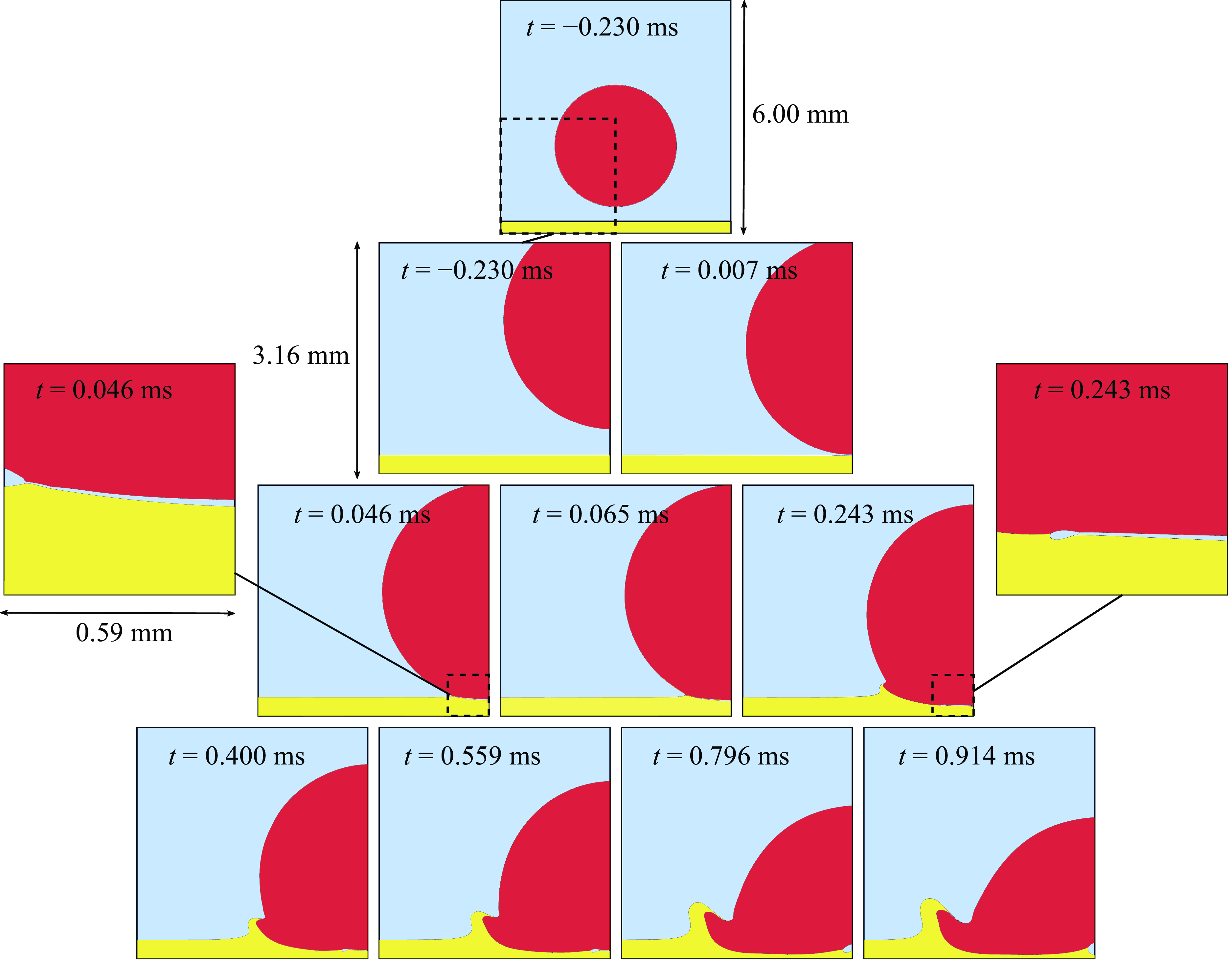
would intersect the substrate plane. A typical impact is shown in figure 2 for
 $U_0=1.5$
 $\text{m s}^{-1}$
and
 $\mu _o=0.02 \,$
Pa s to illustrate the general dynamics. Although specific treatment was used for the triple point, we have checked that the dynamics does not vary qualitatively as we vary the resolution. As the drop approaches the oil film, both the drop underneath the surface and the oil film deform until a thin layer of air is entrapped when the drop touches the oil film (left-hand zoom image). Later, this entrapped air film retracts because of surface tension until it forms a bubble underneath (see the last image for
 $t=914$
μs). On the other hand, the impact generates a corona made of both water and oil at later times.
Snapshots of the impact at several time steps (indicated on the images), with different geometrical sizes. The top image shows the initial condition, while the pyramidal images below it present the dynamics at scale two. Two zoom images (scale 1/10) on the left and right of the pyramid illustrate the formation and retraction of the air film entrapped by the impact. The first contact between the water droplet (red) and the oil substrate (yellow) occurs at around
 $46$
μs. Then a small disc of gas (in blue) is entrapped and retracts, while a corona made of a mix of oil and water emerges from the impact at longer times.

In this paper, we thus focus on the physical characteristics of the bubble entrapment, i.e. formation time and geometrical dimensions.
2.3. Definition of the contact
It is worth noting that since the gas layer obeys the lubrication regime, mathematically the contact between the drop and the film cannot happen in a finite time in the presence of surface tension by only considering the Navier–Stokes equations (Duchemin & Josserand Reference Duchemin and Josserand2010; Yeganehdoust et al. Reference Yeganehdoust, Attarzadeh, Karimfazli and Dolatabadi2020). In fact, physical contact arises rapidly after the gas film thickness becomes locally less than a microscopic cut-off length scale usually of the order of a few hundreds of nanometres, below which other mechanisms dominate: surface interactions, non-continuum effects or thermal fluctuations, for instance (see a recent review (Sprittles Reference Sprittles2024) for a comprehensive analysis of these effects). Numerically, contact occurs as soon as a triple line can exist, that is, when the three phases are present in the same cell. This happens thus when the gas layer reaches the size of the minimal mesh size, which plays here the role of the cut-off length. Therefore, we define later the contact as when the minimal gas film thickness
 $h_{min}(t)$
(see figure 1) attains the size of our smallest mesh (here
 $1/2^{12}$
of our computational domain, corresponding to a cut-off length of
 $3.7$
μs). Although our numerical cut-off is at least one order of magnitude larger than the usual microscopic length, we numerically verified that our results were not depending qualitatively on the precise value of this length (see Appendix A). Finally, it is important to note that in the present study, since we determine the bubble entrapment just when a triple point appears, the numerical issues related to the treatment of the triple point do not play a role, neither does the contact angle for impacts onto a solid substrate. Such details are considered within the context of a current comprehensive study.
3. Results and film effects
To establish a baseline, first we present the results for the birth of a bubble for drop impact onto a solid surface. Dimensionless variables are shown using overbar notation.
3.1. Drop impact over a solid
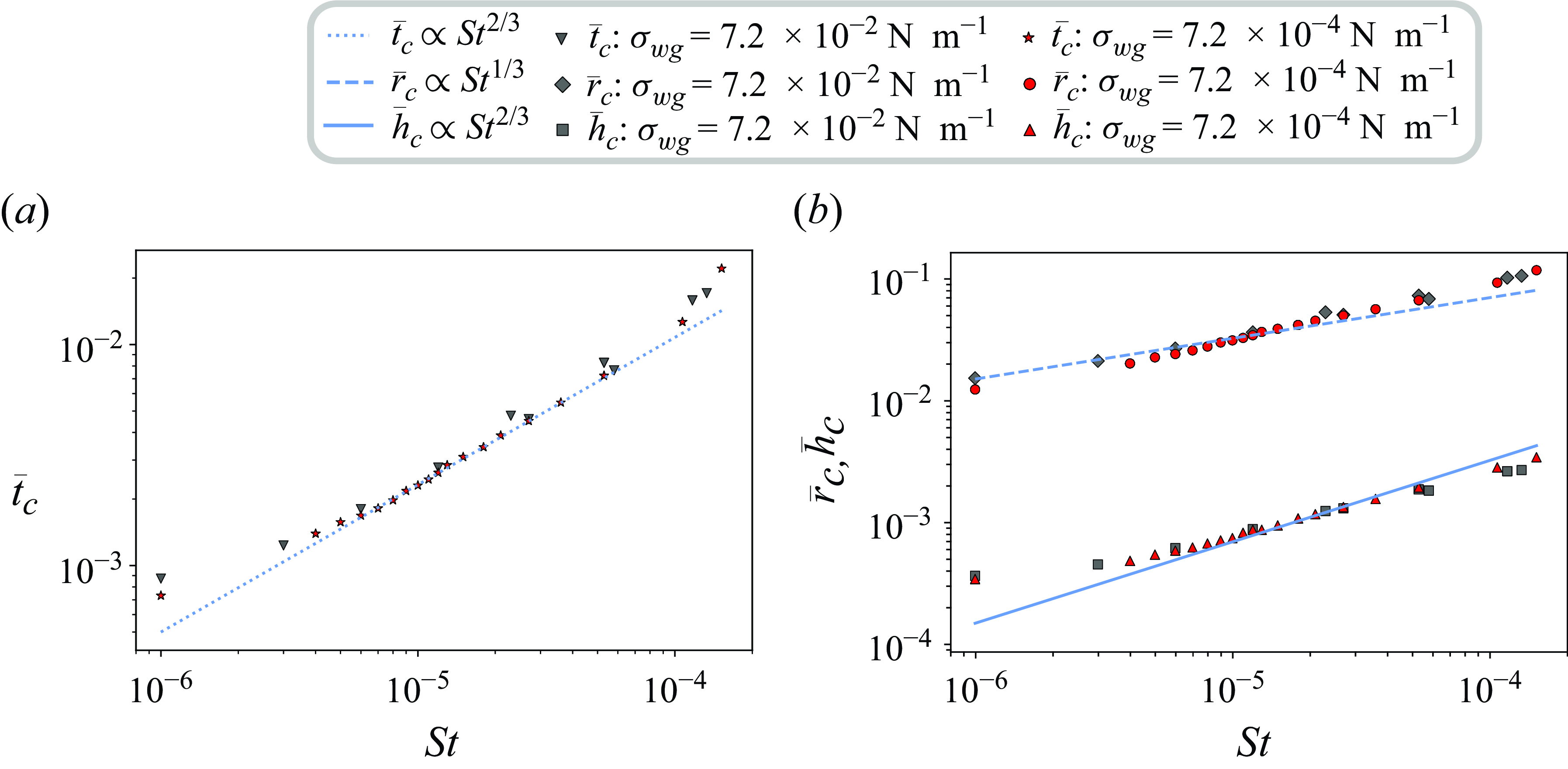
(a) Dimensionless time of contact
 $\bar {t}_c$
of a drop impacting on a solid as a function of the Stokes number
 $St$
. The data are obtained for two surface tensions, grey
 $\sigma _{wg}=7.2 \times 10^{-2}$
and red
 $\sigma _{wg}=7.2\times 10^{-4}$
 $\text{N m}^{-1}$
, varying both the impact velocity and the gas viscosity. The expected scaling law
 $St^{2/3}$
is indicated (blue line). (b) The dimensionless radius
 $\bar {r}_c$
(upper curve) and central height
 $\bar {h}_c$
(lower curve). Both are in agreement with the predicted scaling laws
 $St^{1/3}$
(
 $St^{2/3}$
).

Figure 3(a) shows the contact time between the impacting drop and the solid substrate as a function of the the Stokes number. The Stokes number is varied by changing the impact velocity, but also by modifying the gas viscosity to cover a wide range of values. A good agreement between the data with the
 $St^{2/3}$
scaling law predicted by the models balancing the inertia of the impact with gas lubrication is observed (Mandre et al. Reference Mandre, Mani and Brenner2009; Duchemin & Josserand Reference Duchemin and Josserand2010; Bouwhuis et al. Reference Bouwhuis, van der Veen, Tran, Keij, Winkels, Peters, van der Meer, Sun, Snoeijer and Lohse2012). Results for two different values of the gas–liquid surface tension,
 $\sigma _{wg}=0.072\ \text{N m}^{-1}$
(grey points) and 100 times smaller (in red), show that the surface tension has very little influence on the contact in the frame of our study, as assumed in the theoretical predictions. Our dataset is bound at high Stokes number by the finite size effect: indeed for
 $St\gt 10^{-3}$
the contact diameter has the same order of magnitude as the droplet diameter so that the hypothesis leading to the scaling law (see model below) is no longer applicable. On the other hand, at low Stokes numbers (below
 $10^{-6}$
) the limit of the resolution is clearly reached. Recall that the main physical ingredients of the model that predicts the
 $St^{2/3}$
scaling (Duchemin & Josserand Reference Duchemin and Josserand2010) is based on a comparison between the lubrication pressure due to the cushioning of the air and the pressure needed to deform the droplet when approaching the substrate. If air pressure is larger than that to deform the droplet, contact with the substrate is avoided, and the contact time is when these two pressures balance. To estimate these pressures, we use the scaling argument that the radial length scale (denoted here generically as
 $r_d(t)$
; see figure 1
b) of the deformation is related to the vertical scale of the drop deformation (
 $h_d(t)$
) through the geometry of the drop
 $ r_d =\sqrt {2 R_0 h_d}$
, notably highlighted by Philippi et al.(Reference Philippi, Lagrée and Antkowiak2016). We can then relate the vertical scale to the time through
 $h_d=U_0 |t|$
. For
 $t\lt 0$
, this vertical scaling corresponds to the air layer between the falling drop and the substrate, while for
 $t\gt 0$
it indicates the height of the drop that has been deformed horizontally because of the substrate. The lubrication equation for the gas-layer thickness
 $h(r,t)$
in axisymmetric geometry is
 \begin{equation} \frac {{\rm d}h}{{\rm d}t}=\frac {1}{r}\frac {\partial }{\partial r}\left (\frac {h^{3}r}{3\mu _g}\frac {\partial P}{\partial r}\right), \end{equation}
where
 $P$
is the pressure in the gas film. Using the geometrical relations for the horizontal and vertical scales introduced above, we obtain the following scaling for the lubrication pressure in the gas as a function of time:
 \begin{equation} P_{lub} \sim \frac {\mu _g r_d^2 U_0}{h_d^3} \sim \frac {\mu _g R_0}{U_0 t^2}. \end{equation}
This lubrication pressure is responsible for droplet deformation prior to contact with the substrate. We thus need first to determine when it is enough to delay this contact. For this purpose, one has to estimate the inertial pressure
 $P_{in}$
that is needed to deform horizontally the drop when approaching the substrate. We can consider that the deformation is located in the half-sphere of radius
 $r_d$
inside the droplet, leading to the scaling for this inertial pressure as
 \begin{equation} P_{in} \sim \rho _w U_0 \frac {{\rm d}r_d}{{\rm d}t}\sim \rho _w U_0^2 \frac {R_0}{r_d} \sim \rho _w U_0^2 \sqrt {\frac {R_0 }{U_0t}}. \end{equation}
We can infer, by comparing these two pressures
 $P_{lub}$
and
 $P_{in}$
, the qualitative behaviour of the effect of the gas layer on the impact process: for negative times, much before the drop is close to the substrate, the lubrication pressure is much smaller that the inertial one, and the drop falls without deformation. As
 $|t|$
decreases (
 $t$
being still negative) the lubrication pressure increases until it becomes larger that the inertial one; at this moment the droplet starts to deform due to the gas cushioning, creating a dimple beneath the drop. The lubrication pressure dominates the inertial one, indicating that the drop can deform enough to avoid touching the substrate even for a positive time! Further on, as the lubrication pressure decreases more rapidly than the inertial one for a positive time (since
 $P_{lub} \propto ({1}/{t^2})$
whereas
 $P_{in} \propto ({1}/{\sqrt {t}})$
for
 $t\gt 0$
), the gas cushioning cannot support the deformation of the drop any longer and it has to contact the substrate. Bubble formation is thus related to the deformation of the droplet at the contact time that a thin air disc is trapped between the substrate and the droplet. The disc will later retract into a bubble due to surface tension. With such dynamics, the contact time can be estimated by balancing the two pressures, leading to
 \begin{equation} \bar {t}_c=\frac {U_0t_c}{R_0} \sim St^{2/3}. \end{equation}
Parameter
 $\bar {t}_c$
can be interpreted both at the typical time before the impact when the drop starts to deform (
 $t\lt 0$
) and that when the contact with the substrate occurs (
 $t\gt 0$
). Within this framework, the surface tension is neglected, which is validated here by our numerical simulations (see figure 3 which shows no variation as the surface tension was reduced by two orders of magnitude), although it can slightly affect the dynamics, particularly for drop deformation (Klaseboer et al. Reference Klaseboer, Manica and Chan2014). We can also deduce from the time of impact the scaling for the thickness and the radius of the entrapped bubble at the contact:
 \begin{equation} \frac {h_c}{R_0}=\bar {h}_c \sim St^{2/3} \;\;\quad\mbox{and}\quad \;\; \frac {r_{c}}{R_0}=\bar {r}_{c} \sim St^{1/3}. \end{equation}
Figure 3(b) shows the central height of the drop
 $\bar {h}_c$
and the dimple radius
 $\bar {r}_{c}$
at the time of impact as functions of the Stokes number for our numerical simulations of impacts on a solid substrate. Although the best-fit analysis of the data would give
 $0.4\pm 0.05$
for the radius scaling and
 $0.55\pm 0.05$
for the central height, the agreement with the predicted scaling, shown in figure 3, is still qualitatively good.
The bubble formation when a drop impacts a solid is thus mainly controlled by the lubrication of the gas layer. This leads to different scaling, functions of the Stokes number, and we now investigate how this dynamics is affected when the impact is made on a thin liquid film.
3.2. Drop impact over a thin liquid film
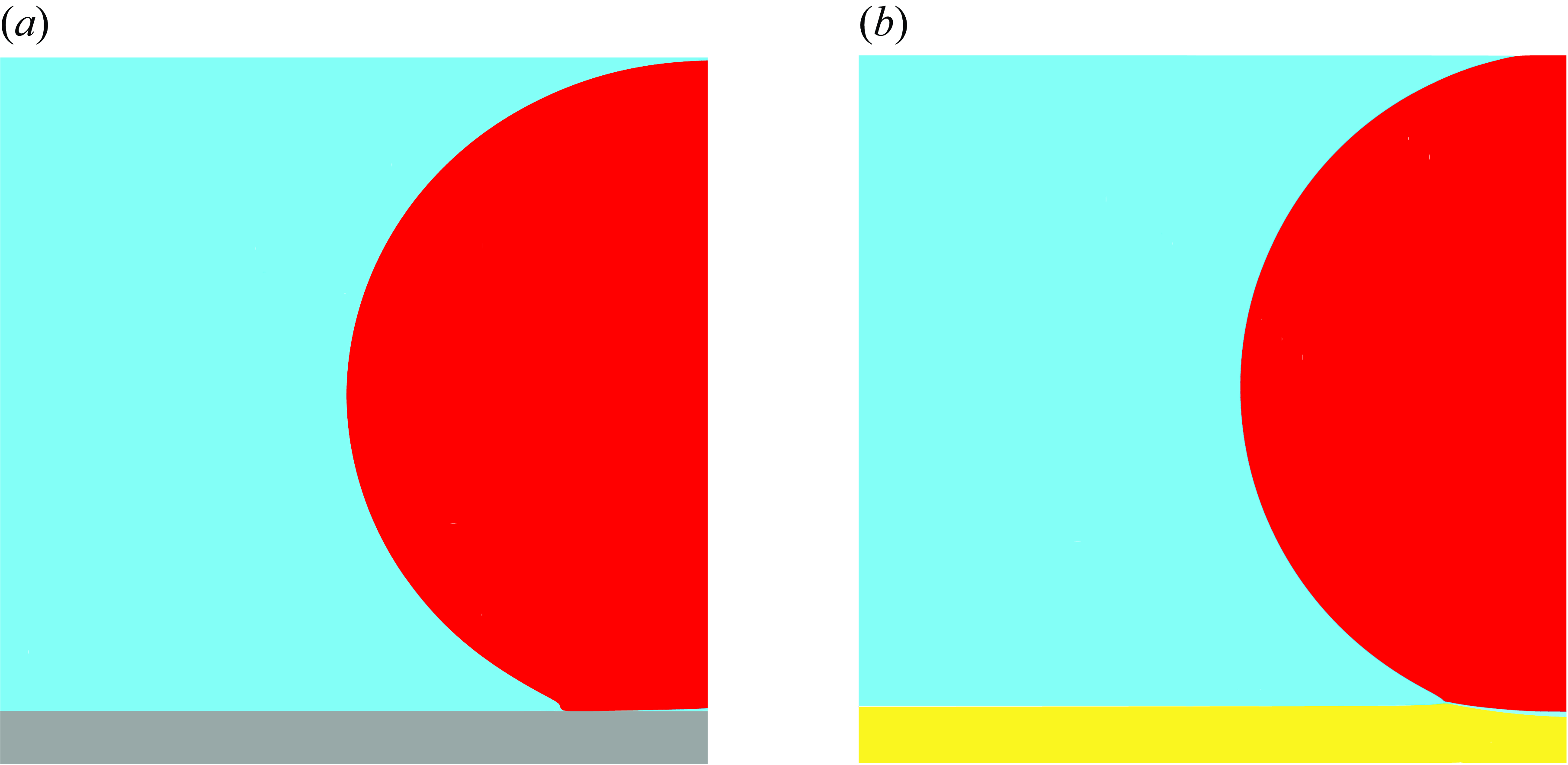
When the substrate is replaced by a thin liquid film, the impact differs, as illustrated in figure 4 where a small deformation of the liquid film is also observed.
Snapshot at
 $t=0.034$
 $\text{ms}$
. (a) Impact over a solid substrate. (b) Impact on a liquid film. The initial conditions for the two cases are exactly the same:
 $R_0=3$
mm,
 $h_{0}=0.3$
mm,
 $U_0=1$
 ${\rm m\, s}^-{^1}$
,
 $\mu _w=0.002$
 ${\rm Pa\,s}$
,
 $\mu _o=0.02$
 ${\rm Pa\,s}$
,
 $\sigma _{wg}=0.07$
,
 $\sigma _{wo}=0.039$
,
 $\sigma _{og}=0.032$
 ${\rm N\, m}^-{^1}$
,
 $Re=1500$
,
 $We_{wg}=43$
,
 $St=5.3\times 10^{-5}$
.

Notably, the influence of the liquid film on the contact time cannot be deduced a priori: on the one hand, one would expect the contact to happen earlier since the gas cushioning is facilitated by the film due to viscous entrainment (Lo et al. Reference Lo, Liu and Xu2017; Duchemin & Josserand Reference Duchemin and Josserand2020); on the other hand, the film deformation should delay the contact.
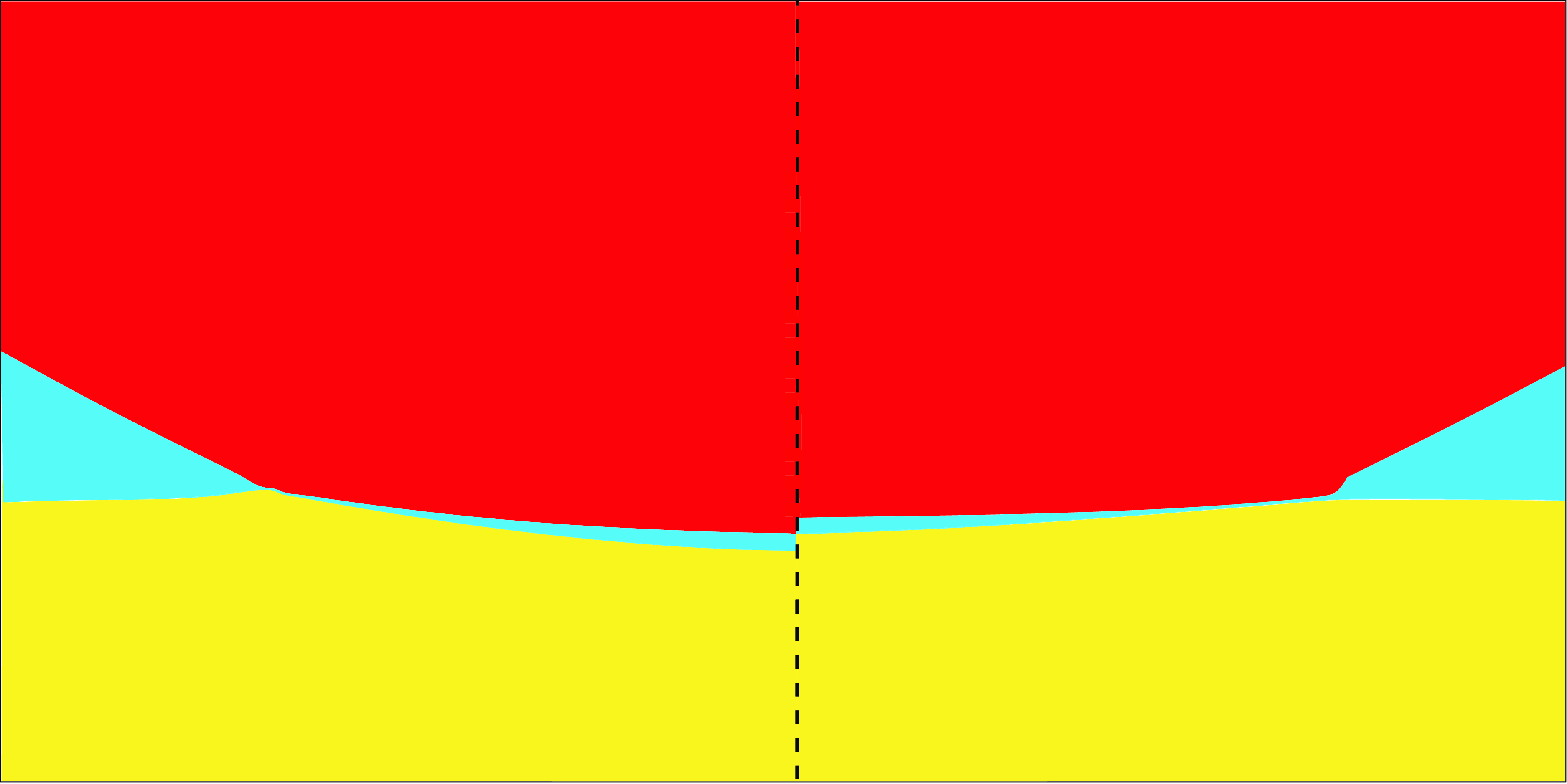
Two snapshots (
 $t=0.034$
ms) for two similar impacts on different oils (left:
 $\mu _o=\mu _w=0.002$
 ${\rm Pa\,s}$
; right:
 $\mu _o=0.02$
 ${\rm Pa\,s}$
). The bubble size is dependent on the oil viscosity. Simulation realised with the following parameters:
 $St=5.3\times 10^{-5}$
,
 $U_0=1$
 ${\rm m\, s}^-{^1}$
,
 $D_{0}=3$
mm,
 $h_{0}=0.3$
mm,
 $\sigma _{wg}=0.032$
,
 $\sigma _{wo}=0.039$
,
 $\sigma _{og}=0.07$
 ${\rm N\,m}^{-1}$
.

Snapshots of the dimensionless pressure (
 $t=0.011$
ms) for two similar impacts on different oils (left:
 $\mu _o=\mu _w=0.002$
 ${\rm Pa\,s}$
; right:
 $\mu _o=0.02$
 ${\rm Pa\,s}$
). Simulation realised with the following parameters:
 $St=2.66\times 10^{-5}$
,
 $U_0=2$
 ${\rm m\, s}^{-1}$
, the others parameters being the same as those in figure 5.

The film deformation is due to the impact pressure exerted by the drop on the film transmitted by the air layer, as illustrated in figure 6. In fact, as explained by Hicks & Purvis (Reference Hicks and Purvis2011), depending on the impact parameters and the oil-film thickness and viscosity, the oil-film deformation can be considered inviscid (for low oil viscosity or/and large film thickness) or viscous (thin film and/or low oil viscosity). The dependence of the deformation with the oil viscosity can be indeed observed in figure 5, where a zoom of the entrapped bubble is presented at the contact time for two different oil viscosities,
 $\mu _o=\mu _w=0.002$
 ${\rm Pa\,s}$
on the left and
 $\mu _o=0.02$
 ${\rm Pa\,s}$
on the right, showing that the smaller the viscosity, the larger the deformation.
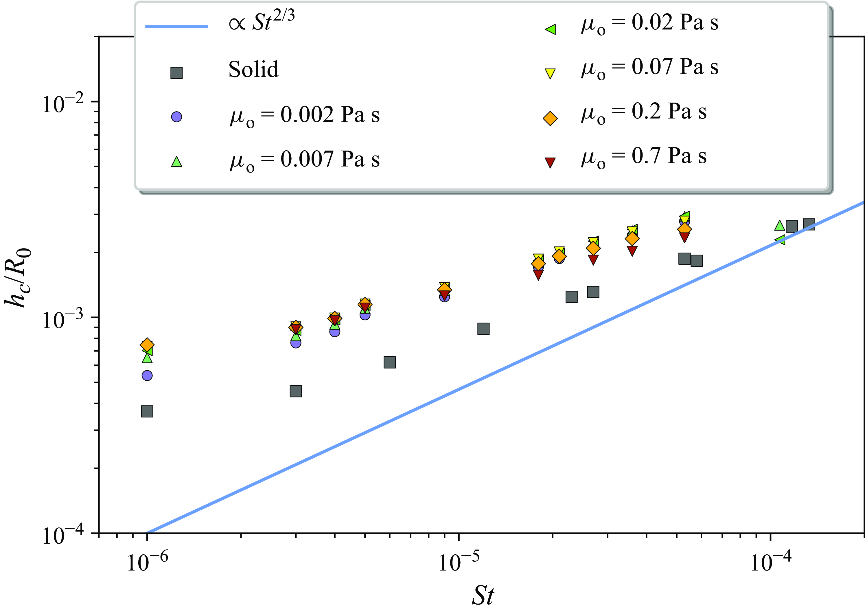
To investigate quantitatively the influence of the thin liquid film in the bubble formation mechanism, different sets of numerical simulations were done by varying the impact velocity and different oil viscosities. The results are shown in figure 7 for thickness
 $\bar {h}_c$
of the gas layer entrapped at the contact time as function of the Stokes number. One can observe that the gas layer (and the contact time) is systematically higher than that for the impact on the solid substrate, indicating that the delay due to the oil film cushioning dominates as the gas cushioning increases. Furthermore, it can be noticed that these two counteracting effects (oil cushioning and interface deformation) are not similar for large Stokes numbers (roughly above
 $10^{-5}$
) where the more viscous cases converge towards the solid case. By contrast, for small Stokes numbers (below
 $10^{-5}$
) the results arrange differently with the oil viscosity. Finally, it is worth noting that the
 $St^{2/3}$
scaling still appears to hold qualitatively for the variation of
 $h_c/R_0$
as a function of the Stokes number for each oil viscosity. However, performing a best-fit analysis for constant oil viscosity data gives lower exponents (around
 $0.5$
) with larger error bars. Therefore, we observe a clear dependence for the oil viscosity that needs to be elucidated.
Dataset for the trend at different Stokes numbers with various oil-layer viscosities. The
 $St^{2/3}$
scaling is still observed. All of these impact cases lead to larger gas-layer thicknesses at the contact time compared with the solid surface impact. We also note a complex dependency for oil viscosity.

3.3. The new scaling law for birth of a bubble
To account for the influence of the film deformation on the dynamics of bubble formation we first characterise numerically the deformation of the film
 $\delta \epsilon$
as the difference between the height of the oil surface under the centre of the droplet at the contact time and the initial thickness of the oil film (see figure 1
b). Since the oil layer can be deformed, the droplet can continue its fall under the original height of the oil layer before making contact, which was not possible for a rigid solid. Then it is tempting to adapt the model derived for the solid substrate to that with the liquid film by taking into account that the drop can now go below the initial surface of the oil film before contacting the oil. This means that the inertial pressure
 $P_{in}$
needed to deform the drop is lowered because of the film deformation. Indeed the substrate is also moving during the fall, and then delays the contact compared with the impact onto solid surfaces. The inertial pressure can thus be deduced as a first approximation from (3.3):
 \begin{equation} P_{in}=\rho _wU_0^{2}\sqrt {\frac {R_0}{h_d+\delta \epsilon }}. \end{equation}
On the other hand, if we assume that the scaling for the lubrication pressure equation (3.1) remains unchanged, we obtain the following relations using, as for drop impact on the solid substrate, the balance between the two pressures:
 \begin{equation} \frac {h_c}{R_0}\sim St^{2/3}\left (1+\frac {\delta \epsilon }{h_c}\right)^{1/3}, \quad \frac {r_c}{R_0}\sim St^{1/3}\left (1+\frac {\delta \epsilon }{h_c}\right)^{1/6}, \quad \frac {U_0 t_c}{R_0} \sim St^{2/3}\left (1+\frac {\delta \epsilon }{h_c}\right)^{1/3}. \end{equation}
These relations suggest that the Stokes number of the impact is simply replaced by an effective Stokes number:
 \begin{equation} St_{eff}=\sqrt {\left (1+\frac {\delta \epsilon }{h_c}\right)}St, \end{equation}
which involves the oil film deformation
 $\delta \epsilon$
. Remarkably, our argument on the deviation of the pressure because the oil film has deformed is somehow similar that that used by Howland et al. (Reference Howland, Antkowiak, Castrejón-Pita, Howison, Oliver, Style and Castrejón-Pita2016) to explain the delay of the splashing threshold for impact on soft surfaces.
We just need therefore to determine how
 $\delta \epsilon$
varies with the impact parameters. Figure 8 shows the variation of
 $\bar {\delta \epsilon }=\delta \epsilon /R_0$
as a function of the Stokes number for different viscosity ratios
 $\mu _g/\mu _o$
(figure 8
a), or equivalently as a function of the viscosity ratio for different Stokes number (figure 8
b). We observe that the deformation is the lowest for the highest oil viscosity (low viscosity ratio
 $\mu _g/\mu _o$
) and that it almost does not depend on the viscosity ratio for small Stokes number.
Deformation of the oil film
 $\bar {\delta \epsilon }=\delta \epsilon /R_0$
(a) for different viscosity ratios as a function of the Stokes number and (b) for different Stokes number as a function of the viscosity ratio. The line in (a) indicates the
 $St^{2/3}$
scaling law consistent with the behaviour of the gas thickness below the droplet.

To explain the behaviour of
 $\bar {\delta \epsilon }$
it is interesting to estimate whether the oil film can be considered inviscid or in the lubrication regime. Hicks & Purvis (Reference Hicks and Purvis2011) have shown that it depends on the ratio between the film thickness
 $h$
and the viscous length
 $ ( ({\mu _o}/{\mu _g})St)^{1/3}R$
. Therefore, if
 $ ( {h}/{R})^{3} \gg ({\mu _o}/{\mu _g})St$
, the oil-film deformation can be considered inviscid because either the oil viscosity is small or the film thickness is large: in both cases the oil layer can deform easily. On the other hand, when the oil viscosity is large or the film thickness small, following
 $ (h/R)^{3} \ll (\mu _o/\mu _g)St $
, the oil film deforms less easily and obeys a lubrication dynamics. In our study where the drop radius and film thickness are taken constant, the following asymptotic regimes for
 $\bar {\delta \epsilon }$
are finally observed:
-
(i) For small viscosity ratios, corresponding to very viscous oil,
 $ ({\mu _g}/{\mu _o}) \ll St ({R}/{h})^{3}$
, we see a small deformation of the oil film. As such, we can deduce
$\bar {\delta \epsilon }$
by using the lubrication equation (3.1) for the oil film (taking thus
$\mu _o$
and a film thickness almost constant
$h_o$
), the thickness variation using the scaling for the pressure from the impact on solid substrate, yielding the scaling(3.9)
\begin{align} \bar {\delta \epsilon } \sim \frac {\mu _g}{\mu _o} St^{-4/3}. \end{align}
-
(ii) For high viscosity ratio,
$ {\mu _g}/{\mu _o} \gg St ( {R}/{h})^{3}$
, the oil film can deform easily. In this case, the lubrication of the gas film separating the droplet and the liquid film is similar to (3.1), the only change being in the prefactor (
$1/12$
instead of
$1/3$
), so that we can deduce(3.10)
\begin{align} \bar {\delta \epsilon } \sim St^{2/3}. \end{align}


These two asymptotic behaviours can be tested by plotting
 $\bar {\delta \epsilon }St^{-2/3}$
as a function of the rescaled variable
 $\xi =( {\mu _g}/{\mu _o}) St^{-2}$
; a linear behaviour for small
 $\xi$
and a constant one for large
 $\xi$
are seen in Figure 9. These two behaviours can be combined using a Padé approximation, leading to the following expression for the deformation:
 \begin{equation} \frac {\delta \epsilon }{R_0}St^{-2/3}=A\frac {\frac {\mu _g}{\mu _o}St^{-2}}{B+\frac {\mu _g}{\mu _o}St^{-2}}, \end{equation}
where the constants
 $A=7$
and
 $B=3 \times 10^{5}$
can be fitted from our data, as shown in figure 9(a). These constants still contain all the physics of the parameters which are maintained constant in the frame of our study. Using a Padé approximation is a natural way to combine two asymptotic regimes without introducing additional contribution. In addition to its fitting features, it can be taken as the simplest approach to associate two regimes only.
(a) Oil film deformation
 $\bar {\delta \epsilon }$
divided by
 $St^{2/3}$
as a function of the rescaled variable
 $\xi = ({\mu _g}/{\mu _o}) St^{-2}$
. The Padé approximation accounting for the two asymptotic behaviours is shown as a dashed line. (b) Thickness of the gas layer rescaled using the new scaling law. We see collapse of the data on the solid line, in agreement with the
 $2/3$
scaling.

Finally, we can deduce from this former scaling on
 $\delta \epsilon /R_0$
a scaling for
 $\delta \epsilon /h_c$
, using the asymptotic behaviour of
 $h_c$
for solid substrates (
 $h_c \sim St^{2/3}$
), yielding
 \begin{equation} \frac {\delta \epsilon }{h_c}=C\frac {\frac {\mu _g}{\mu _o}St^{-4/3}}{B+\frac {\mu _g}{\mu _o}St^{-2}}, \end{equation}
where
 $C=7 \times 10^{-3}$
is directly deduced from
 $A$
. We can now combine the two equations (3.7) and (3.12) to obtain the new expressions of the scaling laws for the bubble entrapment:
 \begin{eqnarray} & \bar {t_{c}}=\frac {U_0 t_c}{R_0}\sim \frac {h_c}{R_0}\sim St^{2/3}\left (1+C\frac {\frac {\mu _g}{\mu _o}St^{-2}}{B+\frac {\mu _g}{\mu _o}St^{-2}}\right)^{1/3}, \end{eqnarray}
 \begin{eqnarray} & \frac {r_c}{R_0}\sim St^{1/3}\left (1+C\frac {\frac {\mu _g}{\mu _o}St^{-2}}{B+\frac {\mu _g}{\mu _o}St^{-2}}\right)^{1/6}.\end{eqnarray}
Note that these scalings are consistent with the expressions deduced for the impact on a solid substrate: indeed, taking a solid as the limit when the oil viscosity diverges, the viscosity ratio goes to
 $0$
and the previous scaling equations (3.5) are recovered. Using this new scaling we obtain a collapse of all our data for impacts over a liquid film with those of the impact on a solid substrate (figure 9
b). It therefore highlights and quantifies the influence of the oil viscosity on the entrapment; as such we have shown that the cushioning of the gas layer dominates the bubble entrapment dynamic, but also that the oil-film deformation cannot be neglected since it controls the delay of the entrapment.
3.4. Other results and discussion
We present in figures 10 and 11 the rescaled results obtained for the time of the contact and the radius of the gas disc. We clearly observe a good collapse of the data for the contact time
 $t_c$
, which is in agreement with the measurement of
 $h_c$
. For the radius, all the raw data align well with the
 $St^{1/3}$
and the solid surface data. However, the rescaling does not lead to a good collapse. This can be explained by the complex film deformation, since we are only considering the value of the deformation under the centre of the droplet. In fact the film is deformed everywhere under the droplet, especially at the contact points, where a very small dimple appears as shown in figure 5. Since this effect is not taken into account in our model, we cannot expect a good collapse of the data for the radius. Finally, although experimental measurements on the geometry of the entrapped bubble in such configuration do not exist yet, experimental comparisons should be available following the observations already done for same liquid impact on a deep pool (Thoraval et al. Reference Thoraval, Takehara, Etoh and Thoroddsen2013; Tran et al. Reference Tran, de Maleprade, Sun and Lohse2013).
(a) Raw data for the time of contact
 $t_c$
. (b) Rescaled impact time with the effective Stokes number.

(a) Raw data of the gas disc radius
 $r_c$
measured at the contact time
 $t_c$
. (b) Rescaled radius with the effective Stokes number.

4. Conclusion
We have investigated the influence of an immiscible thin film on the bubble entrapment dynamics following a droplet impact, focusing in particular on the role of the oil viscosity. We show that the lubrication of the gas layer is still the main effect controlling the dynamics of bubble formation, but that the oil viscosity plays an important role for understanding the film influence compared with the impact on a solid substrate. Indeed, the cushioning of the gas layer, when the drop approaches the oil film, does deform both the drop and the oil film. This second deformation is at the origin of the delay observed for bubble entrapment. By accounting for this deformation in the model, we obtain a new expression which fits well our data. Further work should investigate the influence of the other physical parameters, in particular the thickness of the oil layer (Hendrix et al. Reference Hendrix, Bouwhuis, van der Meer, Lohse and Snoeijer2016) which should highlight the transition between the viscous and the inviscid regime for the oil film.
Acknowledgement.
It is our pleasure to thank the Fonds Franco-Canadien pour la Recherche (FFCR) for its support through the project ‘Impact de gouttes sur film liquide’.
Declaration of interests.
The authors report no conflict of interest.
Appendix A.
As explained in the main text, the contact is determined when the three phases are present in the same computational cell. We have performed a sensitivity study for the case of an impact over a solid surface to investigate the influence of the maximum mesh resolution. The contact is determined when the minimum thickness of the gas layer is below a threshold, basically equal to the size of the smallest cell. Figure 12 shows the time of contact
 $t_c$
and the central height of the gas layer
 $h_c$
for different maximum mesh levels from levels 10 to 13. We observe a very low dependency on the mesh level for level 12 and above, justifying the use of level 12 in our computations.
(a) Dependence of the mesh refinement on the measurement of the contact time
 $t_c$
. (b) The thickness below the centre of the droplet
 $h_c$
for a droplet impact over a solid substrate.