1. Introduction
Quadruped robots, an important branch in the field of robotics, have raised research interests because of their strong locomotive ability over wheeled and tracked robots on rough terrains. The work involves locomotion speed, flexibility, and stability as integral parts of the advantages of quadruped robots, which also explain why the quadrupeds occupy a considerable number in nature. To date, there were many developed quadruped robots and some of them showed excellent performance, such as Cheetah [Reference Seok, Wang, Meng Yee, Otten, Lang and Kim1], Tekken [Reference Fukuoka, Kimura, Hada and Takase2], HyQ [Reference Boaventura, Medrano-Cerda, Semini, Buchli and Caldwell3], Puppy1 [Reference Iida and Pfeifer4], Rush [Reference Zhang and Kimura5], BigDog [Reference Raibert, Blankespoor, Nelson and Playter6], LittleDog [Reference Zico Kolter and Ng7], Baby Elephant [Reference Chen, Gao, Qi, Tian and Zhang8], Hexa-XIII [Reference Mao, Tian, Gao and Zhao9], and Origaker [Reference Zhang and Dai10], [Reference Tang, Qi and Dai11].
Of all the work, the stability as a vital evaluation indicator for quadruped robots raised concerns by many researchers. As it is essential to the locomotion of quadruped robots [Reference Zhang, Zhang, Dai and Qi12], several methods have been proposed to evaluate it. The Static Stability Margin proposed by McGhee and Frank [Reference McGhee and Frank13, Reference Mcghee and Iswandhi14] is the first criterion of the stability of quadruped robots, defined as the shortest distance between the projection of the robot’s center of gravity (COG) and the edges of the support polygon on the ground. Furthermore, the Longitudinal Stability Margin [Reference Zhang and Song15], the Crab Longitudinal Stability Margin [Reference Zhang and Song16], and the Energy Stability Margin (ESM) [Reference Messuri and Klein17] were presented. The Normalized Energy Stability Margin is proposed by normalizing the ESM to the robot weight [Reference Hirai, Hirose, Haikawa and Takenaka18]. As the dynamic control of the robot has also been used [Reference Spyrakos-Papastavridis, Dai, Childs and Tsagarakis19], the Dynamic Stability Margin [Reference Hof, Gazendam and Sinke20], namely the shortest distance from the center of pressure to edges of the support polygon, was presented. The Normalized Dynamic Energy Stability Margin [Reference Garcia and de Santos21] was defined as the minimum energy required to tumble the robot around edges of the support polygon. Among the static and dynamic approaches, the capability to resist the tumble caused by disturbances was named as Tumble Stability [Reference Yoneda and Hirose22, Reference Zhang, Chai and Dai23]. When large changes exist in the height of COG, the energy-based stability margins are more suitable for the stability analysis compared with the distance-based ones. As a result, the energy method is selected to analyze the process of backflip in this paper.
Among all stability issues of quadruped robots, overturning is one of the essential issues. Overturning caused by slipping, falling, and collision is very common in the animal world. Similarly, it is unavoidable for quadruped robots. In many cases, the working environments of a quadruped robot are in absence of human operators, such as the tunnel detection and the planetary exploration, which raises the requirement of self-recovery ability.
The importance of self-recovery has been recognized by the robotics community. Solutions to the disability of a robot caused by overturning have been applied to some wheeled robots. The Nanorovers [Reference Tunstel24], a wheeled robot developed for the planetary exploration, could use an autonomous recovery function with the specially designed wheel structure. A hopping robot with a triangular prism can execute a two-stepped self-recovery strategy when the robot landed incorrectly [Reference Hale, Schara, Burdick and Fiorini25]. Actuated wings were designed by Chen Li [Reference Li, Kessens, Young, Fearing and Full26] for self-recovery, as inspired by cicada that opens its wings to push against the ground for self-recovery. Furthermore, an idea gained from Chinese mitten crabs was reported to solve the self-recovery problems [Reference Riphaus, Hoffmann and Labisch27]. A framework for generating quasi-static self-recovery solutions for generic robots was developed by Kessens and Dotterweich [Reference Kessens and Dotterweich28] using Inertial Appendage Methods. For legged robots, work has been presented on six-legged robots. A hexapod robot named the RHex [Reference Saranli, Buehler and Koditschek29] achieved the self-recovery ability, which was further improved by a specially designed controller [Reference Saranli and Koditschek30]. Utilizing the inertia with a dynamic process and extra boosters or multiple legs to gain more support points, a solution was proposed by Peng [Reference Peng, Ding, Yang and Xu31] for a hexapod robot to plan the self-recovery motion. The humanoid robot possessing relatively slender limbs with large workspace can stand up by supporting with its legs and arms and following a sequence of contact states [Reference Kanehiro, Kaneko, Fujiwara, Harada, Kajita, Yokoi and Isozumi32].
However, a quadruped robot encounters problem when applying the methods above. First, the structure restriction of the quadruped robot that having only four legs leads to the lack of support points. Second, in consequence of pursuing good flexibility and high speed, the restriction of weight and power does not allow it to be equipped with some extra boosters such as long extended arms, rotating wheels or other auxiliary devices. As a result, the self-recovery for a quadruped robot is more challenging to implement. As the risk of overturning caused by external disturbances is unavoidable, there is a strong demand for the self-recovery ability of quadruped robots. For some quadruped robots, such as HyQ [Reference Semini, Tsagarakis, Guglielmino, Focchi, Cannella and Caldwell33], Spot [34], Jueying [35], and ANYmal [Reference Hutter, Gehring, Lauber, Gunther, Bellicoso, Tsounis, Fankhauser, Diethelm, Bachmann, Bloesch, Kolvenbach, Bjelonic, Isler and Meyer36], they can lie on one side after a fall because of the special designs of the trunk shape and COG location. The Spot Arm of Boston Dynamics even has a gripper of six degrees of freedom, which can provide a support force when getting up [37]. Thus, it is easy for them to stand up after falling on the ground. To our knowledge, the Mini Cheetah is the first example of a quadruped robot executing dynamic 360° backflip from standing [Reference Katz, Carlo and Kim38]. Nevertheless, the backflip of Mini Cheetah is relatively energy consuming. During a flip, the height of its COG reaches a peak of 0.7 m, and the maximum output power is 690 W. Besides, this robot requires high precision in both design and control, as very slight errors will result in a bad landing configuration. The same problems exist with the backflip of Stanford Doggo [Reference Kau, Schultz, Ferrante and Slade39]. In this work, an alternative quasi-static strategy was proposed to endow the quadruped robots, especially these in a supine position, with self-righting capability. In order to verify the proposed backflip strategy, we adopt a control algorithm mainly based on the kinematic model, rather than dynamics or model-free control [Reference Spyrakos-Papastavridis and Dai40, Reference Li, Kang, Branson and Dai41].
This paper aims to develop a kinetostatic backflip strategy for the self-recovery of quadruped robots based on the principles of minimum force and energy. In the proposed backflip process, support points are initiated in every control interval to make the robot stable. Many low-cost quadruped robots that have open-loop controllers and ordinary actuators are difficult to adopt most of the existing self-recovery methods. This paper provides a solution for them. Based on the analysis of minimum force and energy, the strategy is also expected to provide an energy-saving self-recovery approach for other types of robots. Considering the difficulty of self-recovery of a quadruped robot, this solution not only requires less on power, dynamic performance, and extra boosters, but also improves the robustness of the recovery movement.
2. Backflip in the Animal World for Self-Recovery
In the animal world, it is a common phenomenon that animals overturn accidentally and recover immediately. When initially placed upside down on ground, the turtle twists and flexes its neck so that its head lifts the front of the broad flat trunk to rotate around the longitudinal axis [Reference Domokos and Várkonyi42, Reference Ruhr, Rose, Sellers, Crossley and Codd43]. Cockroaches bends their trunk into a U shape, thus the feet can touch the ground and push the trunk to flip over [Reference Full, Yamauchi and Jindrich44]. Rats have relatively slender body and are more likely to land their feet on the ground. They first rotate their necks and heads upright, then turn their trunks to bring the rear legs in contact with the ground [Reference Full, Yamauchi and Jindrich45]. When turning over, ladybirds use their claws to hook the ground, to pull their body to roll. On smooth surfaces, they deploy the hind wings and turn over with the help of both legs and wings [Reference Zhang, Li and Li46].
The actions animals take for self-righting are usually indifferent by people. Although they conduct these actions unconsciously, the skills are gradually improved and optimized during evolution. With the observation of these, we can find the principle of backflip strategy and apply it in the robot. Faisal [Reference Faisal and Matheson47] studied the self-recovery behavior of locusts after overturning, and found that when animals’ trunks are not equal in length and width, they are more inclined to choose the longitudinal edge of the body as the axis of rotation to flip. Similarly, we found that the auto-selection of rotation axis when a quadruped executes a backflip follows an indistinguishable rule.
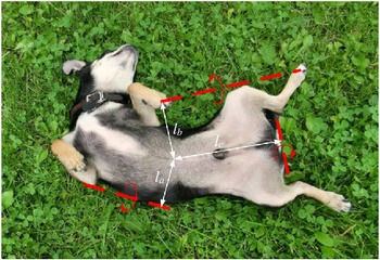
For example, as shown in Fig. 1, when a dog is lying on the ground and needs to perform a self-recovery, it has three ways to flip over, from the left-hand side or the right-hand side or the fore-aft direction. These ways can be distinguished by the rotation axis that the dog selects. To reduce the minimum energy required, the distance as an arm between the center and the rotation axis should be as small as possible, thus the dog naturally chooses to use the rotation axis on its shortest side of the trunk (l a ) as the shortest arm, rather than on the longer sides (l b ) and (l c ). Since the mass of the trunk is constant, shorter force arm significantly decreases the torque required for the self-recovery. Thus, it is an energy-saving approach used naturally by selecting the rotation axis at the shortest side of the trunk. In fact, dogs naturally pick this approach to perform the self-recovery action. Thus, dogs usually choose the side with the shortest force arm of the trunk as the rotation axis. (l a < l b < l c ). It is noted that this experience is also applicable for other legged animals. The experience gained from the animal wisdom provides an inspiration for the robot’s backflip strategy.
Strategy that a dog takes when it flips over.

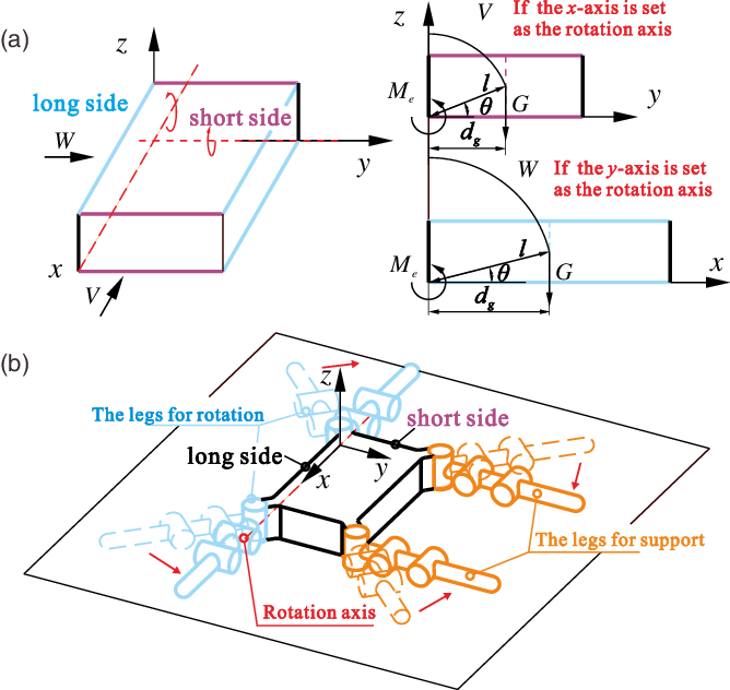
Selection of the rotation axis. (a) A mathematic model is established to calculate the gravitational moment Mg. (b) Choosing the short side as rotation axis is compared with the selection of the long side as the rotation axis. (c) The robot spreads the legs of one side into a “T” shape to show its rotation axis on the edge of the trunk.

3. Rotation Axis Selection Based on Kinetostatic Analysis
With the analysis of the animals’ behaviors, we apply this experience to the design of a backflip strategy to achieve the self-recovery. Although quadruped robots have a variety of shapes, the rotation axes [Reference Dai48, Reference Dai49] could be regarded as fixed on the ground. The optimal selection of a rotation axis is validated with a mathematical model, as shown in Fig. 2(a). In the rotation process, the trunk is supported and lifted by the legs. Therefore, the legs need to overcome the gravitational moment. According to Newton’s law, we get
 \begin{align} {M_e}-{M_g} = I\alpha, \end{align}
where M g is the gravitational moment that the legs need to overcome, M e is the moment provided by the legs, I is the moment of inertia, and α is the angular acceleration, which is considered as zero in this static case. Then Eq. (2) can be derived from Eq. (1).
 \begin{align} {M_e} = {M_g} = G{d_g} = {\rm mgl\;}{\rm{ }}{\rm cos}\theta, \end{align}
where d
g
is the force arm of the gravity, G is the gravitational force, m is the mass of the robot, and g is the gravitational acceleration. The edge distance l represents the distance between the center of the robot and the rotation axis on the edge, and the lifting angle
 $\theta$
represents the angle between the level ground and the perpendicular line from the COG to the rotation axis, as shown in Fig. 2(b).
As mass m is fixed, both the edge distance l and the lifting angle
 $\theta$
contribute to the change of M
e
. It is noted that the smaller the M
e
is, the less force that the robot legs need to support the trunk. Different choices of the rotation axis in Fig. 2(b) lead to the changes of the edge distance l, lifting angle
 $\theta$
, and the force arm of the gravity d
g
. Obviously, when the long side with shorter edge distance is selected as the rotation axis, d
g
is relatively shorter, which will lead a smaller moment M
e
. The result turns out to be the same as the natural selection strategy in the animal kingdom.
Therefore, the first step is to select a rotation axis with a minimal edge distance l. The edge of long side of the trunk that has the shortest distance to the COG is selected as the rotation axis. To form a rotation axis, the legs near the rotation axis are rotated to be aligned with the rotation axis, and are selected as the legs for rotation. The legs away from the rotation axis are selected as the legs for support. The designed posture of the robot is displayed in Fig. 2(c). Thus, the four legs are divided into two groups: legs for rotation and legs for support. The legs for rotation are close to the rotation axis, and the legs for support are away from the rotation axis.
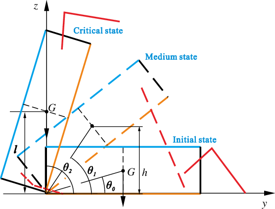
Rotation process of the backflip. The rotation process starts from the initial state to the critical state. After the legs for support leave the ground, the legs for rotation need to bear all the weight of the trunk. The medium state is defined as the process after the legs for support leave the ground and before the robot falls down by the gravity. The work required from the medium state to the critical state is calculated and analyzed. Since the critical position is determined, the rotation work is mostly affected by the height of COG.

4. Motion Planning and Foothold Trajectory
After selecting the rotation axis, the robot starts to move its legs for backflip. Based on the rule of minimum rotation energy, the motion planning of the legs for support is proposed. The foothold trajectory of the legs for rotation is analyzed and designed with consideration of rotation force and stability.
4.1. Motion planning of legs for support based on minimum rotation energy
Note that, the COG in this paper is defined as the mass center of the trunk, as the four legs are symmetrically arranged around the trunk, and the mass of each leg is much smaller than that of the trunk. Considering that the previous movement is the preparation of flipping, the next step is to use the legs on the rotation side to flip the trunk. Since lifting the trunk requires the legs to overcome the gravity, we describe the rotation process in terms of the energy conservation. As shown in Fig. 3, the rotation process starts from the initial state (
 $\theta$
0) to the medium state (
 $\theta$
1), then to the critical state (
 $\theta$
2). The initial state is defined as the state when the trunk is lying on the ground. The medium state is defined as the state after the legs for support lift the trunk and before the legs for rotation move. The critical state is defined as the position where the projection of COG on the ground passes through the axis of rotation. After the critical position, the gravity of the robot powers the rotation process to its end. In the rotation process from the initial state to the medium state, the legs for support provide supporting forces, keeping the robot’s balance. After the medium state, the legs for support will leave the ground and the legs for rotation will take their duty to rotate the trunk to the critical state. During the process from the medium state to the critical state, the whole weight of the trunk will be imposed on the legs for rotation. In this step, the torque of each actuator in the rotation leg is relatively larger in the whole process. Therefore, we manage to optimize this torque by analyzing the work required from the medium state to the critical state. The work required in this step is obtained by
 \begin{align} W & = \int_{{\theta _1}}^{{\theta _2}} {{M_{\rm{e}}}} d\theta \\ & = \int_{{\theta _1}}^{{\theta _2}} {mg \cdot l \cdot \cos \theta } d\theta \\ & = mgl\left( {\sin {\theta _2} - \sin {\theta _1}} \right) \end{align}
where
 $\theta$
1 and
 $\theta$
2 represent the lifting angles at the medium state and the critical state, respectively. As shown in Fig. 3,
 $\theta$
1=arcsin(h/l) and
 $\theta$
2=
 $\pi/2$
. Substituting the values of
 $\theta$
1 and
 $\theta$
2 into Eq. (3) yields
 \begin{align} W{\rm{ = }}mg\left( {l - h} \right), \end{align}
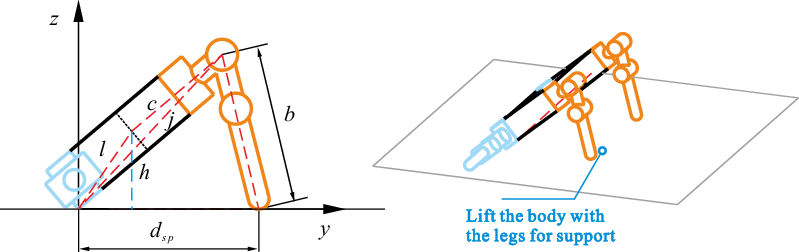
where h is the height of the COG in the medium state. As shown in Fig. 3, W the work required from the medium state to the critical state is changed with h of the medium state. This part of work is only provided by the legs for rotation, thus the demand for the actuators in the legs for rotation is more stringent. Therefore, according to Eq. (4), the core goal of this step is to increase h to reduce W by elevating the trunk from the initial state to the medium state. The legs for support were designed to move at the robot’s back side and lift the trunk to increase h, as shown in Fig. 4. This strategy takes advantage of the structural feature that the legs of the robot can move above the back of the robot. For animals, like the turtle, their legs cannot reach their back side, which make it more challenging for them to perform a backflip. As a result, some animals rely on the inertia by shaking their bodies to achieve a backflip. Unlike these animals, this strategy breaks the limitation of the animal and finds a beyond-biology method for the robot.
Lifting the trunk to the medium state. The legs for rotation stay still while the legs for support move downward to lift the trunk to the medium state. This action will enlarge h and decrease the rotation work W.

As is shown in Fig. 4, at the medium state, the legs for support stand on the ground, and h changes with the movements of the legs for support. h is derived as
 \begin{align} h = l \cdot \sin \left( {\arccos {{{l^2} + {j^2} - {c^2}} \over {2jl}} + \arccos {{{j^2} + {d_{sp}}^2 - {b^2}} \over {2j{d_{sp}}}}} \right), \end{align}
where j represents the distance between the rotation axis and the knee joint of the legs for support, c represents the distance between the COG and the knee joint of the legs for support, d sp represents the distance between the footholds of the legs for support and the rotation axis, and b represents the distance between the hip joints and the footholds of the legs for support.
Since the size of the trunk is fixed, j, c, and l are constant parameters. Based on Eq. (5), h is enlarged by increasing b and decreasing d
sp
. As a result, we minimize the rotation work W
m−cr
by lifting the trunk as high as possible, as shown in Fig. 4. When b is equal to the maximum length of the leg for rotation, and
 ${j^2} = {b^2} + d_{sp}^2$
, h reaches its maximum value.
4.2. Motion planning of legs for rotation based on minimum rotation force
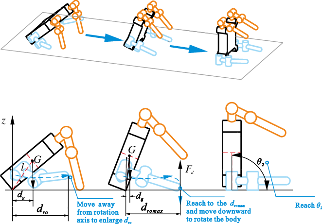
After lifting the trunk to the medium state, we need to continue rotating the trunk to the critical state. Unlike other methods, the kinetostatic method needs sustaining and stable support points to keep balance. Considering the legs for support cannot further lift the trunk, we need to use other legs to flip the trunk. Hexapod robots have other two legs except for the legs for support and the legs for rotation. These two extra legs can provide driven force to rotate the trunk. As for quadruped robots, it becomes extremely more challenging because only legs for rotation can be used to lift and rotate the whole robot. In this work, we find a way to use the legs for rotation to provide torque around the rotation axis and plan its foothold trajectory based on the kinetostatic analysis of the rotating force. The process of this action is shown in Fig. 5. The legs for rotation move to bring their footholds away from the rotation axis to enlarge d ro . Here, d ro is defined as the rotation action distance, which represents the distance between the footholds of the legs for rotation and the rotation axis. The rotating force F d provided by the legs for rotation, referring to Fig. 5, can be derived by the torque equilibrium equation:
 \begin{align} {F_d} \cdot {d_{ro}} - G{d_g} - mal = 0\hbox{'} \end{align}
where d g represents the force arm of the gravity to the rotation axis, and it is only affected by the location of COG. a is the acceleration of the COG, which is set as zero in this static situation. Accordingly, the rotating force can be obtained by
 \begin{align} {F_d} = {{G{d_g}} \over {{d_{ro}}}}. \end{align}
Rotating the trunk with the legs for rotation. First, the legs for support stay still to keep the trunk balanced, while the legs for rotation move away from the rotation axis. After the rotation action distance dro increases from 0 to its largest value dromax that depends on the leg’s workspace, the legs for rotation move downward and rotate the trunk to critical state Θ2, where the gravity direction of the robot passes through the rotation axis.

Here, the rotating force F d is restricted by the power of the actuators, and we need to minimize it to reduce the power requirement. To achieve the goal of the minimum rotation force, increasing the rotation action distance d ro is a feasible way, as other parameters are fixed. In Fig. 5, the trajectory of the legs for rotation is designed. In the beginning, the legs for rotation start moving from the position where d ro is approximately zero. Subsequently, as the legs for rotation move away from the rotation axis toward the boundary of the workspace, d ro increases and reaches the maximum value d romax . After that, the legs for rotation move downward against the ground and rotate the trunk to the critical state. During this process, the legs for support leave the ground, and the torque is entirely provided by the legs for rotation. This action is important to the whole strategy.
4.3. Foothold trajectory planning for stable rotation
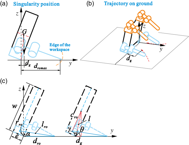
In the preceding section, the movement strategy of the legs for rotation is proposed based on the concept of minimum rotating force. However, when reaching the maximum distance d romax , as shown in Fig. 6(a), the legs for rotation are restricted by their workspace, and the foothold movement is not fully controllable due to the singularities. To overcome this problem, the trajectory of the foothold needs to be re-planed, enabling the legs for rotation to gain more reachable space in vertical direction. In this section, the workspace is defined as the area projected on yz plane by the reachable volume of the foot tip. For more detailed workspace analysis considering both trunk and leg motions, please refer to works [Reference Dai, Holland and Kerr50, Reference Cui and Dai51]. As is shown in Fig. 6(b), to enlarge the workspace in z-direction, the footholds of the legs for rotation should be placed closer to the rotation axis following the foothold trajectory. With this action, the legs for rotation will leave the singular position and increase the workspace in vertical direction. It should be noticed that the distance d ro decreases during this action. However, the closer the footholds are to the rotation axis, the lower the stability margin of the robot and the greater the risk of falling will be. To make sure that the trunk can be stably rotated, we need to analyze the change of d ro in Fig. 6(c) and get the condition that d ro must satisfy for a stable rotation operation.
Singularity avoidance, geometrical condition of stability, and the trajectory planning. (a) When the legs for rotation reach the edge of their workspace, the singularity issue should be concerned, as the foothold movement is not fully controllable due to the singularities. (b) To overcome this issue, the trajectory of the foothold is also designed to move toward the rotation axis when it moves downward, so as to enlarge the workspace in vertical direction. However, the minimum value of dro should satisfy the critical rotation condition. (c) The relationships between the rotation action distance dro and the parameters of the robot.

According to the law of cosines (Fig. 6c), we get
 \begin{align} {d_{ro}}^2 - 2{d_{ro}}{r_{ro}}\cos {\alpha _{ro}} + {r_{ro}}^2 - {l_{ro}}^2 = 0, \end{align}
where r ro is the distance between the hip joint of a rotation leg and the rotation axis, which can be expressed as
 \begin{align} {r_{ro}} = \sqrt {{{\left({w \over 2} - {c_{ro}}\right)}^2} + {{\left( {{e \over 2}} \right)}^2}}, \end{align}
where w and e denote the width and thickness of the trunk, respectively. l ro represents the length between the hip joint of a rotation leg and its foothold, which keeps changing during the rotating motion. α ro is the angle between r ro and the ground, which can be written as
 \begin{align} {\alpha _{ro}} = \theta + \gamma, \end{align}
where
 $\gamma$
is a physical parameter related to the robot and can be obtained by
 \begin{align} \gamma = \arccos {{{l^2} + {r_{ro}}^2 - {c_{ro}}^2} \over {2l{r_{ro}}}}\text{'} \end{align}
where c
ro
is the distance between the hip joint of the leg for rotation and the COG. Thus, α
ro
changes with
 $\theta$
. From Eq. (8), the rotation action distance d
ro
can be represented as
 \begin{align} {d_{ro}} = {r_{ro}}\cos {\alpha _{ro}} \pm \sqrt {{r_{ro}}^2{{\cos }^2}{\alpha _{ro}} + {l_{ro}}^2 - {r_{ro}}^2}. \end{align}
Here, d ro should always be larger than the gravity distance d g ; otherwise, the trunk will rotate around the line formed by the footholds of the legs for rotation and fall down by the gravity. Thus, we take the larger solution, which is given as
 \begin{align} {d_{ro}} = {r_{ro}}\cos {\alpha _{ro}}{\rm{ + }}\sqrt {{r_{ro}}^{2}\;{{\cos }^2}\;{\alpha _{ro}} + {l_{ro}}^2 - {r_{ro}}^2}. \end{align}
The leg for rotation is designed to move downward while moving horizontally to the rotation axis so as to enlarge its workspace. Based the analysis above, d ro should always satisfy the condition:
 \begin{align} {d_g} \lt {d_{ro}} \lt {d_{romax }}, \end{align}
where the gravity distance d g and the maximum rotation action distance d romax can be expressed as
 \begin{align} \left\{ \begin{matrix} {{d_g} = l{\rm cos}\theta } \\[8pt] {{d_{romax}} = {r_{ro}}\,{\rm cos}\,{\alpha _{ro}} + \sqrt {r_{ro}^2\,{\rm{co}}{{\rm{s}}^2}\,{\alpha _{ro}} + l_{romax}^2 - r_{ro}^2} } \end{matrix} \right.. \end{align}
Here, l romax is the maximum length of the legs for rotation. Eq. (14) defines the reachable range of the foothold of the leg for rotation, which ensure that the robot can rotate stably.
4.4. Bumping protection of the robot with legs for support when the trunk lands on the ground
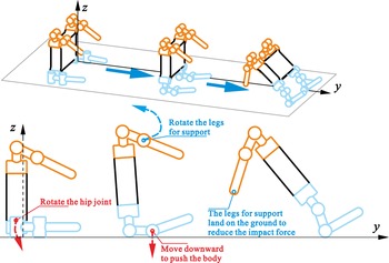
After reaching the critical state, the legs for rotation can move downward to break the balance, and the trunk drops. However, simulation and physical experiments show that the impact on the trunk when landing greatly affects the structure of the trunk, especially for the actuators and the electronic devices. Therefore, the legs for support are designed to move downward while the trunk is falling down, as shown in Fig. 7. In this action, the legs for support contact the ground earlier than the trunk, which could reduce the impact force imposed on the robot. It is considered as bumping protection.
Bumping protection of the robot when landing. The legs for rotation move downward to break the balance and then the trunk falls down due to the gravity. In the meantime, the legs for support rotate toward the belly side of the trunk to reduce the shock by touching the ground earlier.

5. Backflip Strategy and Dimensional Condition for Self-Recovery of Quadruped Robots
In this section, a kinetostatic backflip strategy is proposed. The parameter relationships between the legs and trunk are formulated, which are helpful to judge whether a quadruped robot could implement the backflip strategy and provide reference for the dimension design of the quadruped robot being planned to adopt this strategy.
5.1. Backflip strategy based on the optimal kinematic parameters
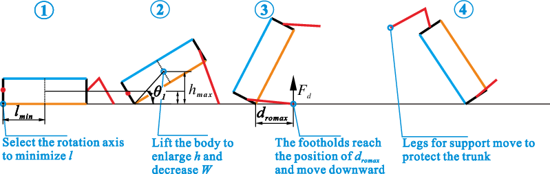
As analyzed in Section 4, the goal of this backflip strategy mainly focuses on optimizing the three kinematic parameters: the edge distance l, the height of COG h, and the rotation action distance d ro . The kinetostatic approach applied to the design of the backflip movement improves the versatility of the strategy so that it can be easily applied to other robots. This strategy consists of four steps, namely, selecting, lifting, rotating, and protecting (SLRP) as shown in Fig. 8. The SLRP is explained as follows:
-
Step 1: Selecting the rotation axis and separating the legs for rotation.
-
Step 2: Lifting the trunk with the legs for support to the medium state
 $\theta$
1.
-
Step 3: Rotating the trunk with legs for rotation to the critical state
$\theta$
2. -
Step 4: Protecting the robot by landing with the legs for support.


Four steps of the kinetostatic backflip strategy. To improve the universality of this strategy, the whole backflip process is divided into four steps and each of the first three steps has a specific parameter to optimize. Steps 1 and 2 minimize the edge distance l and enlarge the height of COG h. Step 3 increases the rotation action distance dro to reduce rotation force Fd and rotates the trunk to the critical position. As for Step 4, it is considered as a protective action by landing with the legs for support when the trunk of robot falls.

5.2. Dimensional condition of the robot for the kinetostatic backflip strategy
It is noteworthy that this backflip strategy is suitable for the quadruped robots, in which the workspace of each leg can reach both the volume above the back and the volume under the belly. Examples are some lizard- or spider-like quadruped robots with legs attached around the trunk (not under the body). The quadruped robot should also meet some dimensional condition to perform this backflip strategy. In this section, we will investigate the parameter relationships amongst the legs, and the trunk to find the condition that guarantees the robot can recovery with this backflip strategy. When rotating from the medium state to the critical state, the footholds of the legs for rotation can either remain unchanged or slide on the ground. We will discuss these two cases separately as follows:
5.2.1 Case 1-Footholds of the legs for rotation remain in situ
For the quadruped robots with relatively slender legs, its footholds can keep in situ during the rotation motion. Referring to Fig. 6, in this case,
 ${d_{ro}}$
keeps unchanged, and the toes of the legs for rotation move downward in the direction perpendicular to the ground. With Eq. (13), the length of the leg for rotation can be obtained by
 \begin{align} {l_{ro}} = \sqrt {{{\left( {{d_{ro}} - {r_{ro}}\cos {\alpha _{ro}}} \right)}^2} + {r_{ro}}^2 - {r_{ro}}^{2}\;{{\cos }^2}\;{\alpha _{ro}}}\;. \end{align}
It can be learnt from Fig. 6(c) that
 ${l_{ro}}$
reaches the maximum value when
 ${\alpha _{ro}} = \pi {\rm{/2}}$
. Thus the maximum length of the leg for rotation must satisfy the following condition:
 \begin{align} {l_{romax}} \gt \sqrt {d_{ro}^2 + r_{ro}^2}. \end{align}
For this case, the preferable value of
 ${d_{ro}}$
is:
 \begin{align} {d_{ro}} = {{{d_g} + {d_{ro\max }}} \over 2}. \end{align}
Because it gives a good trade-off between the rotating force, stability, and the reachable range of the leg for rotation in vertical direction.
5.2.2 Case 2-footholds move toward the rotation axis
This case is designed for the quadruped robots with relatively short legs. By bringing the footholds close to the rotation axis, the required leg length of the robot is reduced in comparison to case 1. In the rotation process, d romax is related to the maximum leg length l romax . The critical rotation condition is determined by the minimum value of d ro , namely d g , which ensures that the trunk will not fall down by the gravity, as showed in Eq. (14).
Substituting Eqs. (13) and (15) into Eq. (14), the condition of the length of the rotation leg is obtained as
 \begin{align} {r_{ro}}\cos {\alpha _{ro}}{\rm{ + }}\sqrt {{r_{ro}}^{2}\;{{\cos }^2}\;{\alpha _{ro}} + {l_{ro}}^2 - {r_{ro}}^2} \gt l\cos \theta\,. \end{align}
Based on Eq. (19), we get
 \begin{align} {l_{ro}} \gt \sqrt {{l^2}\;{{\cos }^2}\;\theta - 2l{r_{ro}}\cos \theta \cos {\alpha _{ro}} + {r_{ro}}^2}\,. \end{align}
In order to satisfy this condition, we need to find the maximum value of the right side of Eq. 20. Thus, we define a function in terms of
 $\theta$
as follows:
 \begin{align} f(\theta ) = {l^2}{\cos ^2}\theta - 2{r_{ro}}l\cos \theta \cos {\alpha _{ro}} + {r_{ro}}^2 \nonumber\\ = {l^2}{\cos ^2}\theta - 2{r_{ro}}l\cos \theta \cos (\theta + \gamma ) + {r_{ro}}^{2}. \end{align}
For simplification, we set
 \begin{align} A = {l^2} - 2{r_{ro}}l\cos \gamma ,B = 2{r_{ro}}l\sin \gamma\,. \end{align}
Substituting Eq. (9) into Eq. (22) yields
 \begin{align} \left\{ \begin{array}{l} A = w{c_{ro}} - {{{w^2}} \over 4} - {{{e^2}} \over 4} \hfill \\[5pt] B = \sqrt {{{\left( {w - 2{c_{ro}}} \right)}^2} + {e^2}} l\sin \left( {\arccos {{{l^2} + {{{w^2}} \over 4} - w{c_{ro}} + {{{e^2}} \over 4}} \over {l\sqrt {{{\left( {w - 2{c_{ro}}} \right)}^2} + {e^2}} }}} \right). \hfill \end{array} \right. \end{align}
Subsequently, f(
 $\theta$
) can be rewritten as
 \begin{align} f(\theta ) & = A{\cos ^2}\theta + B\sin \theta \cos \theta + {r_{ro}}^2\, \nonumber \\& = {{\sqrt {{A^2} + {B^2}} } \over 2}\sin (2\theta + \delta ){\rm{ + }}{A \over 2} + {r_{ro}}^2\,, \\ & \le {{\sqrt {{A^2} + {B^2}} } \over 2}{\rm{ + }}{A \over 2} + {r_{ro}}^2 \nonumber\end{align}
where
 $\delta = \arctan {A \over B}$
. According to Eqs. (20) and (24), we can get
 \begin{align} {l_{ro}} \gt \sqrt {{{\sqrt {{A^2} + {B^2}} } \over 2}{\rm{ + }}{A \over 2} + {r_{ro}}^2}. \end{align}
Equation (25) gives the condition between the minimum length of the legs for rotation and the parameters of the trunk, including the edge distance l, the width of the trunk w, and the thickness of the trunk e. This condition can be used in the design of the quadruped robot that is planned to adopt the kinetostatic backflip strategy. When the size of the trunk and the locations of the legs for rotation are determined, the minimum length of the rotation leg, namely l ro, should satisfy the condition in Eq. (25). It is an essential condition that is helpful to identify whether the workspace of the robot is large enough to perform this backflip strategy.
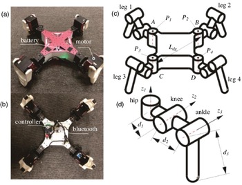
Structure of the DRbot. (a) The top view image of the DRbot with 12 actuators mounted on the joints and a 7.4 V battery inside the trunk. (b) The upward view image of the DRbot with controller and Bluetooth. (c) The structure diagram of the DRbot. (d) The structure diagram of the leg.

6. Simulation and Experiment of the Backflip Strategy
In this section, both simulation and experiments were conducted to validate the proposed backflip strategy. The simulation was carried out in MATLAB and ADAMS with a Computer Aided Design model, and the experiments were performed with a prototype of the spider-like quadruped robot named DRbot.
6.1. Model and prototype of the quadruped robot
The quadruped robot platform named DRbot has a square shaped trunk designed to contain batteries, controllers, and sensors, as shown in Fig. 9(a) and (b). The size of the trunk is defined as AD = BC = L dg . Hip joints labeled as P i are located at the four corners of the trunk, and the four identical legs fixed on the trunk are denoted by leg i (I = 1, 2, 3, 4), respectively. Each leg is a three-bar serial mechanism. The lengths of the links in each leg are represented by d 1, d 2, and d 3, respectively. Each leg consists of three joints, namely the hip joint, knee joint, and ankle joint. The z 1 axis of the hip joint is vertical to the trunk, while the z 2 axis of the knee joint and the z 3 axis of the ankle joint are perpendicular to the hip joint axis, as depicted in Fig. 9(c) and (d). The dimensional parameters of DRbot are listed in Table I. With consideration of the interferences and the limitations of the actuators, the rotation ranges of the three joints of each leg are determined; see Table II.
Structure parameters of the DRbot (mm).

Reachable ranges of the three joints in each leg.

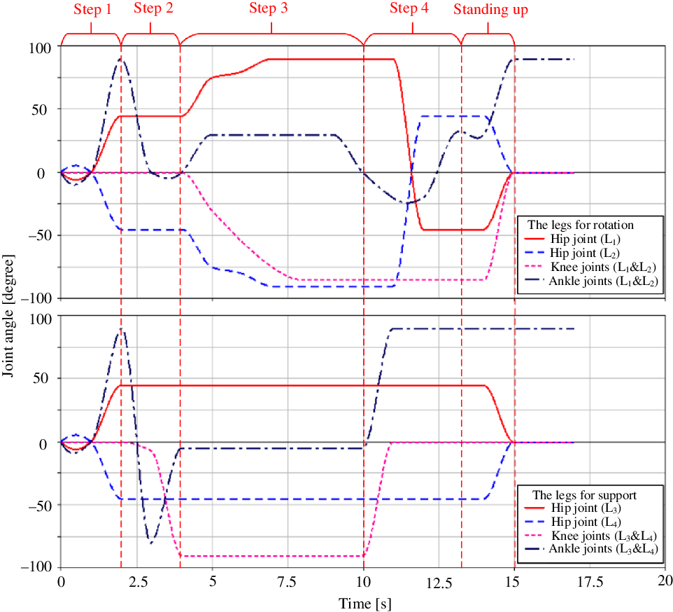
Variations of the joint angles of each leg. The hip, knee, and ankle joints’ angles of each leg are depicted with respect to time.

6.2. Simulation of the backflip strategy with the model
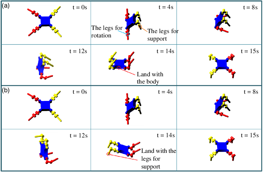
Based on the analysis in preceding sections, a simulation model was established, upon which the kinetostatic backflip strategy was validated. The physic model was first established in Solidworks, and the displacement set of each joint was calculated in MATLAB. The variations of the joint angles of each leg are depicted in Fig. 10. Subsequently, it was imported into ADAMS to verify the implementation of the backflip strategy. The animation results prove that the backflip strategy can stably complete the self-recovery task, as shown in Fig. 11.
Simulation of the backflip strategy in ADAMS. (a) The robot flips without the bumping protection, and the trunk hits the ground. (b) The robot flips with bumping protection and lands with the legs for support.

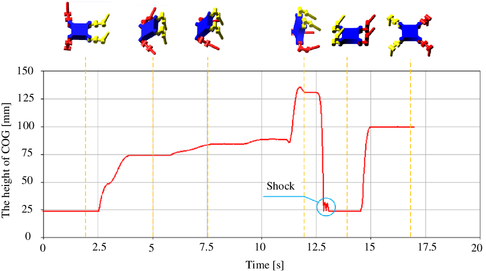
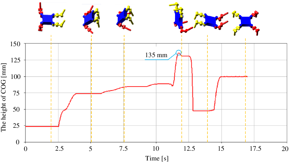
Height variations of COG of the quadruped robot during a backflip circle when landing without protection.

Height variations of COG of the quadruped robot during a backflip circle when landing with legs for support.

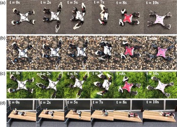
Indoor experiment of the backflip strategy with DRbot. (a) The DRbot easily flipped on the ground when it overturns. (b) The DRbot successfully flipped on loose gravels. (c) The DRbot conducted backflip motion on grass although its support footholds were unstable. (d) The DRbot executed the backflip motion on inclined terrain.

As the two legs for support move symmetrically during the backflip motion, the angles of their hip joints have opposite signs and equal amplitudes, while the angles of knee joints are coincident to each other, as well as the ankle joints; see Fig. 10. The same situation exists in the legs for rotation.
At 0∼2 s, the legs for both rotation and support were determined, and the robot moved to form a T-shaped configuration. Subsequently, the hip and knee joints of the legs for rotation were fixed to form a rotation axis that is able to minimize l, and the legs for support started moving. The ankle joints of the legs for support reversed into the opposite direction, using the workspace at the back side. As a result, the trunk was lifted by the legs for support. At 4∼10 s, the legs for support kept still to hold their positional relationships. At the same time, the joints of the legs for rotation brought their footholds away from the rotation axis. Subsequently, these two footholds moved downward against the ground to rotate the robot to the critical state, and the legs for support rotate to prepare for collision protection. At about 13 s, the robot broke its balance to fall down. Finally, the robot stood up again.
In order to verify the effect of the protection step (Step 4), we conducted a comparative experiment in the simulation, which is shown in Fig. 11. The result of the simulation without protection step is displayed in Fig. 11(a), and (b) shows the result of the action when adding the protection step. The height variations of the COG during the backflip circle have been depicted in Figs. 12 and 13, which indicate the energy changes in these two cases. The maximum height of the COG is 135 mm. Although the action in Fig. 11(a) performed successfully without the bumping protection, the result in simulation showed clearly that the robot encountered strong vibrations when landing, as depicted in Fig. 12. Thus, with no bumping protection of the legs for support, a big shock happened to the trunk, and it may damage the mechanical structure and electronic components. By contrast, when landing with the legs for support, there was no obvious shock.
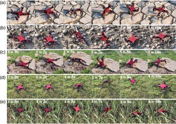
Outdoor experiment of the backflip strategy with DRbot. (a)–(c) The DRbot executed the backflip motion on three typical rocky roads. (d) The DRbot flipped on loose grass. (e) The DRbot successfully performed the proposed backflip strategy on leafy grass.

6.3. Experiment of the backflip strategy with the prototype
A physical prototype of the DRbot was developed, upon which both indoor and outdoor experiment were conducted to demonstrate the feasibility and adaptability of the proposed backflip strategy. Figure 14 shows the results of the indoor experiment, in which DRbot can easily complete the backflip action in various terrains. Fig. 14(a), (b), (c), and (d) shows that the DRbot perform this strategy on ground, gravel, grass, and slope, respectively.
During the backflip, the DRbot always keeps two feet on the ground, which reduces the levelness and smoothness requirements of the ground, and makes it practicable in the real world.
Figure 14(a), (b), and (c) shows the backflips in different terrains. Compared to the ground, gravel road is loose and its footholds are not at the same height. As for the grass, it is soft and may affect the legs for support. In the case we are presenting in Fig. 14(d), the positive elevation of the terrain allows an easier backflip motion with the proposed strategy. On the contrary, bigger effort is required in negative slopes. It is noteworthy that the experiments take less time than the simulation, as each subtask is executed in sequence in the simulation, while in experiments, some subtasks are carried out simultaneously. For example, in Step 2, when the legs for support lift the trunk upward, the legs for rotation can move away from the axis of rotation at the same time.
In order to demonstrate the superior adaptability of the proposed backflip strategy, we further conducted an outdoor experiment with another prototype of DRbot (see video: https://www.bilibili.com/video/BV1dQ4y1r74G?spm_id_from=333.999.0.0). As shown in Fig. 15, this approach can adapt to a variety of real-world terrains, some of which even include relatively challenging obstacles. Compared with the dynamic backflip approach, the kinetostatic backflip strategy based on alternative support of the four legs gains more stability in the whole flipping circle.
7. Conclusion
Interests in quadruped robots have been in the mobility and stability. However, it is inevitable that a quadruped robot capsizes when walking in real complex terrains. Therefore, the ability of self-recovery is in a great demand especially when a robot independently performs tasks without human assistance. This paper proposed a novel quasi-static backflip strategy using a kinetostatic method for quadruped robots to achieve the self-recovery task. Owing to its stable support in each step, this strategy that only relies on four legs of the robot is more versatile. With the analysis of a simplified model of this process, we found several parameters to optimize this strategy and to verify its applicable conditions. Inspired by the animals, we divided this process into four steps, each of which benefited from the strategy optimization. With only four legs in a quadruped robot, the difficulty arises when each leg is required to do a number of actions. Utilizing the kinetostatic backflip method, the robot engages alternatively the legs for rotation and legs for support in each step of the action; thus it does not require additional mechanisms and relies only on itself to complete the action. The analysis, simulation, and experiments proved the feasibility and adaptability of the proposed backflip strategy.
Acknowledgment
The authors acknowledge the support of the National Key R&D Program of China (Grant No. 2018YFB1304600 and 2019YFB1309800), the Natural Science Foundation of China (Project No. 51535008, and 51721003), the Program of International Collaboration (“111 Program”) under Grant No. B16034 and the Engineering and Physical Science Research Council (EPSRC) in the UK under the grant of EP/E012574/1 and EP/S019790/1.
Competing Interests
The authors declare that they have no competing interests.
Data and Materials Availability
All data are provided in this paper and the Supplementary Materials.