I. INTRODUCTION
Advanced technologies set targets for performance of materials that in many cases are difficult or impossible to meet with conventional materials. Common approaches to improving material characteristics, for example, by alloying or thermomechanical processing, are reaching their limits. In a visionary article about the new ways in design of novel materials, Ashby Reference Ashby1 highlighted the potential of hybrid materials, which he defined as combinations of two or more materials whose spatial arrangement adds to the property profile of the resultant material. The material design strategies championed by Ashby Reference Ashby1,Reference Ashby and Bréchet2 are inspired by geometry and introduce shape and arrangement of the building blocks of hybrids as their new ‘degrees of freedom’. Reference Bouaziz, Brechet and Embury3,Reference Embury and Bouaziz4 This geometry aspect defines the hybrid materials as a special case of composites (different from conventional metallic composites produced by traditional methods) with engineered inner architecture.
Relatively recently it was recognized Reference Bouaziz, Kim and Estrin5 that established techniques of severe plastic deformation (SPD) can be used effectively to produce hybrid materials with interesting inner architecture and improved mechanical properties. Indeed, over the past decades SPD processes have advanced to become one of the most potent ways of producing bulk ultrafine-grained materials with exceptional strength characteristics. Reference Valiev, Zehetbauer, Estrin, Hoppel, Ivanisenko, Hahn, Wilde, Roven, Sauvage and Langdon6,Reference Valiev, Estrin, Horita, Langdon, Zechetbauer and Zhu7 By applying SPD techniques to produce hybrid materials, two goals are achieved at the same time: (i) extreme grain refinement with attendant strengthening of the constituents and (ii) attainment of the desired inner architecture of a hybrid. Reference Bachmaier and Pippan8–Reference Beygelzimer, Estrin and Kulagin11
A material design of particular interest is that with a helical geometry of the constituents of a hybrid, which can significantly contribute to improvement of its properties. Reference Bouaziz, Kim and Estrin5,Reference Beygelzimer, Estrin and Kulagin11 Helical architectures are very common in natural biological systems, Reference Wainright, Biggs, Currey and Gosline12–Reference Zhang, Ma, Chen, Kunz, Tamura, Qiang, Xu and Qi14 ensuring a favorable combination of high strength and stretchability. Indeed, multiple helices appear to be the most common spatial arrangement of internal reinforcements for living organisms with a cylindrical or tubular overall shape. In engineered structures, the beneficial effect of reinforcement of a material with helical inclusions on the strain hardening and tensile ductility was demonstrated by Bouaziz et al. Reference Bouaziz, Allain, Barcelo, Niang, Brechet, Embury and Onck15
In earlier reports, examples of producing hybrid materials in the form of spiral-shaped armor embedded in a matrix by SPD were presented. Reference Khoddam, Estrin, Kim and Bouaziz16,Reference Latypov, Beygelzimer, Kulagin, Varyukhin and Kim17 In particular, application of twist extrusion for this purpose was discussed in great detail. Reference Latypov, Beygelzimer, Kulagin, Varyukhin and Kim17,Reference Beygelzimer, Kulagin, Estrin, Estrin, Dunlop, Brechet, Fratzl and Dendievel18 In this article, we present yet another SPD process suitable for producing helical inner architecture of a hybrid material. It is based on continuous shearing of a billet in an equal channel angular pressing (ECAP) die with rotating shear plane. We use the acronym ECAP-R for this process, which is described in Sec. II.B. It was first modeled numerically by finite element (FE) simulations using the QFORM software. 19 Based on the results of the simulations, a special rig was designed, manufactured, and tested using Al/Cu hybrids with different arrangements of the constituents as a model system.
II. MATERIALS AND EXPERIMENTS
A. Material
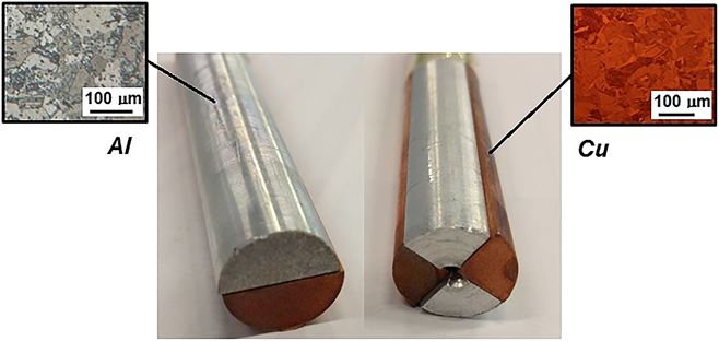
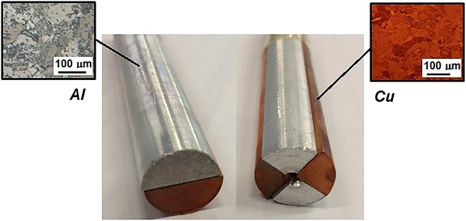
Commercial purity copper and Al1050 rods with an average grain size of 55.5 μm and 50.8 μm, respectively, were used in this study. The rods of 12 mm diameter and 50 mm length were cut along the axis in halves and quarters and hybrid samples were made by putting together two or four matching pieces, as shown in Fig. 1.
Initial arrangement of Al and Cu constituents of a billet prior to deformation by ECAP-R: two-piece billet (left) and four-piece billet (right). (Optical microscopy images of microstructure before deformation is shown in the insets.)
B. Description of experimental rig
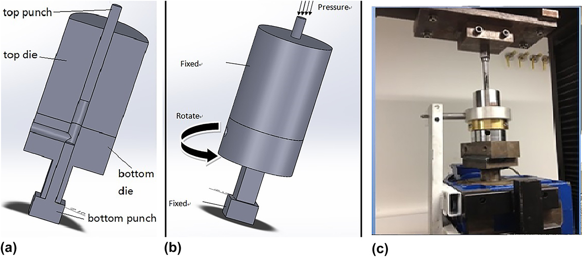
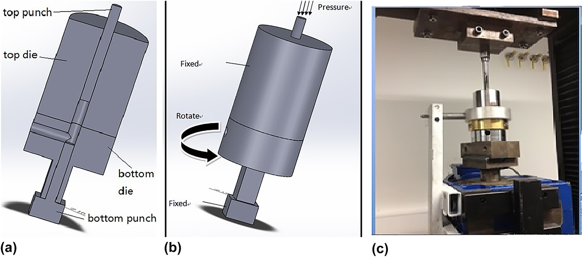
A schematic of the ECAP-R process and the real rig used in combination with a conventional vertical press are shown in Fig. 2.
Schematic of the ECAP-R process and the experimental rig used in the present work. (a) Schematic of half of a die; (b) schematic of loading with rotation of part of the die; (c) photo of the real unit.
C. FE simulation
A number of commercially available software packages such as ABAQUS, ANSYS, DEFORM, QForm, and others have been successfully utilized to study the deformation behavior during SPD. In the present work, the numerical modeling of ECAP with rotating shear plane was performed using the commercial FE package QForm VX. 19 This modeling package is specially designed for metal forming simulations and makes use of a hybrid approach which combines the advantages of the Voronoi Cells approach and the FE method. This software package applies an advanced remeshing algorithm which is capable to refine the mesh either based on tracing the changes in strain or adapting the mesh based on the velocity changes.
The set-up of the simulation included import of the CAD geometry of the top and the bottom dies and the two punches as shown in Fig. 2(a). The dies and punches were simulated as rigid solid bodies. The geometry of the hybrid sample was adopted from the experimental set-up described in Sec. II.B. The top punch had a prescribed constant velocity of 1 mm/s and the bottom die rotated anticlockwise about an axis aligned with that of the entry channel at a constant angular velocity of 5 rpm.
The material parameters for commercial purity copper and Al1050 were selected from the database of QForm VX, where they are represented as stress–strain curves. These flow stress curves, where the stress is represented as a function of strain, strain rate, and temperature are compiled from published data describing the mechanical behavior and matching well our experimental data. The interaction between the parts of the hybrid sample made from different materials can be modeled in several ways. One possibility available in the QForm software is the flexibility of choices of the coefficient of friction. For instance, a relatively high value of µ = 0.8 is assigned to the coefficient of friction, and the constituents of a hybrid billet can potentially slide during the ECAP-R process. This high value of the coefficient of friction is commonly reported in the literature for static friction on clean surfaces of metals which are allowed to slide during the deformation process, see Ref. Reference Blau21.
An alternative possibility is to assume initial bonding/welding between the two constituents of a future hybrid that prevents them from sliding and separating during the ECAP-R process. However, since the experimental assembly was based on a tight fit, rather than welding or mechanical fixtures, this option was not further explored. The frictional behavior of the workpieces was thus modeled using Levanov’s friction law that represents a generalization of the well-established shear friction model established by Orowan. Reference Blau21 The interaction between the workpieces and the dies was simulated by using the same frictional law, yet with a low coefficient of friction to reflect the lubrication between the workpieces and the die. Specifically, two values of the coefficient of friction, namely, 0 and 0.05, were selected.
The assembled sample was discretized using tetrahedron-shaped elements. The number of FEs was increased from the initial 22,000 to 42,000 for single material simulations to account for large strains involved in ECAP-R. In cases where the workpiece consisted of two or four parts and complicated surface interactions had to be computed, the final number of FEs was one order of magnitude higher than the above number, over 200,000 elements. A FE mesh sensitivity analysis was performed and it was demonstrated that doubling the overall number of FEs beyond the above value did not alter the results.
III. RESULTS AND DISCUSSION
A. Comparison of ECAP and ECAP-R processes by FE analysis
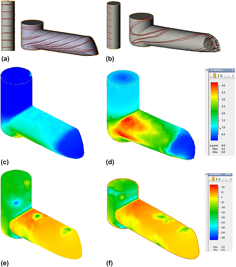
To understand the difference between the deformation modes associated with ECAP with a stationary and a rotating die, deformation of a solid aluminum rod in the two cases was modeled. Deformation can be visualized by tracing markers introduced in the bulk of the billet in numerical simulations, see Figs. 3(a) and 3(b). In the conventional ECAP process, the planes normal to the axis of the entry channel, represented by these markers in Fig. 3(a), undergo simple shear and remain parallel after passing the exit channel. By contrast, in the ECAP-R process, a visible transformation of markers demonstrates formation of helices, Fig. 3(b). Plastic slip of the material normal to the longitudinal axis of the rod adds to the shear strain, which is especially pronounced at the contact surface with the die. These differences are reflected in the distribution of the equivalent von Mises strain shown in Figs. 3(c) and 3(d).
Comparison of ECAP and ECAP-R by FE simulation for a solid aluminum rod. (a, b) Initial markers and their transformed shape; (c, d) distribution of the equivalent von Mises strain; (e, f) distribution of the mean stress after deformation by ECAP (a, c, e) and by ECAP-R (b, d, f).
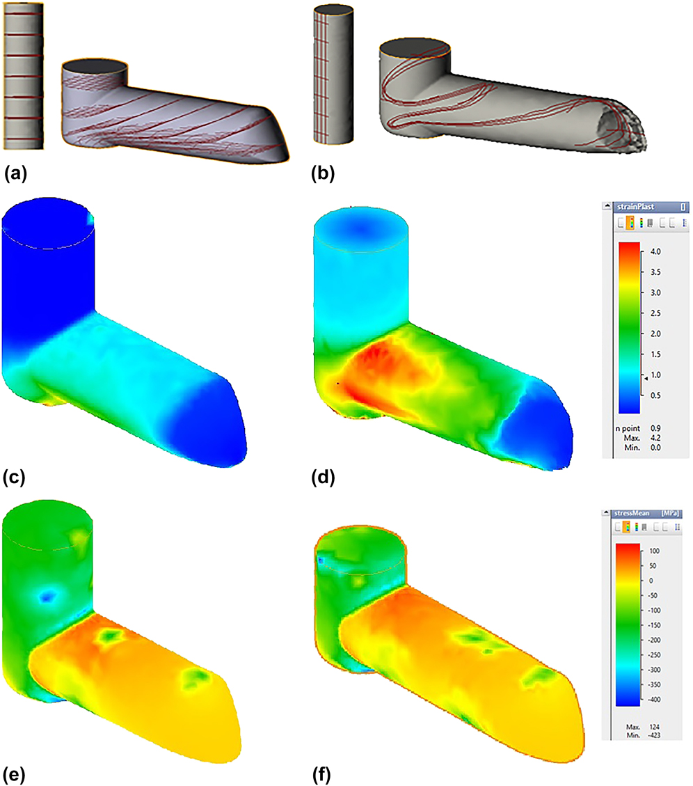
It can be seen that the difference in the magnitude of the equivalent strain at the top surface of the rods processed by ECAP and ECAP-R is as high as 300%. The corresponding distribution of the mean stress (defined as one-third of the first invariant of the stress tensor) seen in Figs. 3(e) and 3(f) exhibits a positive value at the top surface of the rod in both cases. Its magnitude is almost independent of die rotation. This positive local mean stress is detrimental to processability of hybrid materials, as will be shown in Sec. III.D. Only in a region below the middle plane of the billet did the mean stress take negative values in the range of −50 to −80 MPa. Samples cut from this region were investigated by scanning electron microscopy (SEM) to analyze the interface between the two halves of the compound billet.
B. Modeling processing by ECAP-R of a two-piece hybrid material
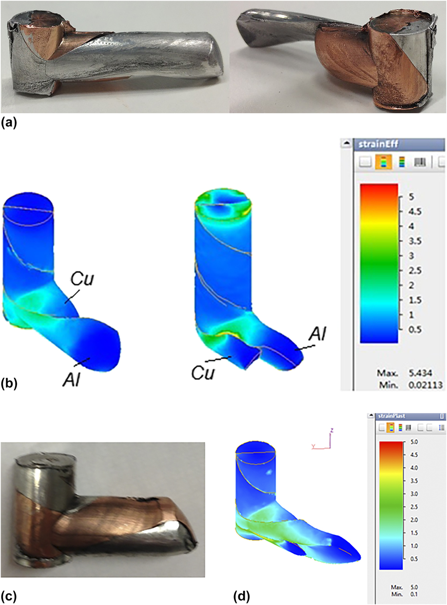
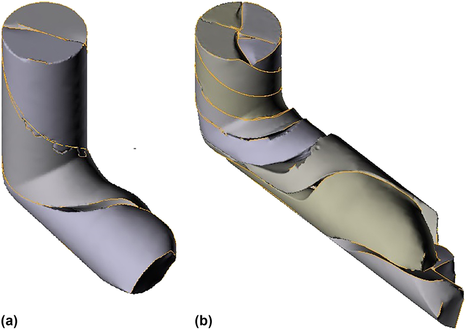
The flow of two-piece hybrid material through the ECAP-R die was dependent on the orientation of the contact plane between the two pieces with respect to the die and on friction between them. In the case the contact plane was perpendicular to the plane of symmetry of the die, the material placed in the upper part of the die overtook that in the bottom part, see Fig. 4(a).
Flow and equivalent strain distribution obtained by FE simulations of a two-piece Al/Cu hybrid. (a, b) With contact plane perpendicular to the symmetry plane of the ECAP-R die; (c, d) with contact plane parallel to the symmetry plane of the ECAP-R die in experiment (a, c) and in simulations (b, c) (left and right pictures in (a) show two different views of the sample).
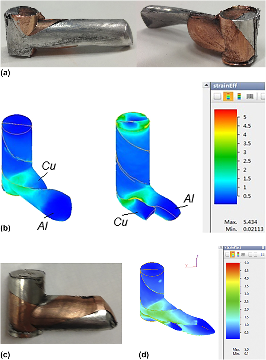
The observed behavior was also confirmed by simulations for a two-piece Cu/Al sample, Fig. 1. As mentioned in Sec. II.C, the coefficient of friction at the contact plane was taken to be 0.8—high enough to prevent sliding between the two pieces, while not precluding them from doing that in principle. However, despite the high friction, one of the materials was flowing faster, Fig. 4(b). The most uniform flow with equal velocities at the die exit was obtained for a case when the plane of contact between the two pieces was parallel to the plane of symmetry, Fig. 4(d). This is consistent with experiment, as illustrated by Fig. 4(c).
C. Modeling processing by ECAP-R of a four-piece hybrid material
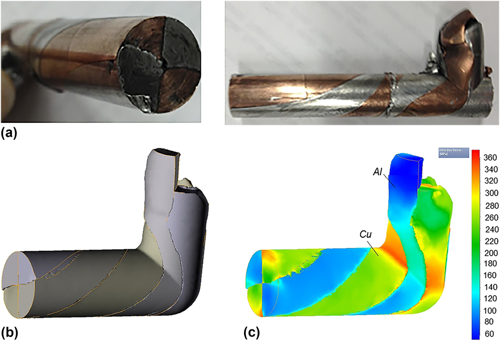
The flow of a four-piece hybrid material through the ECAP-R die was found not to be very sensitive to the orientation of the contact plane with respect to the die. A strong effect of the level of friction between the pieces was observed. The experimental results are summarized in Fig. 5, along with the outcomes of numerical simulations.
Four-piece Al/Cu hybrid processed by ECAP-R. (a) Experiment; (b) FE simulation of billet shape; and (c) FE simulation of the von Mises equivalent stress.
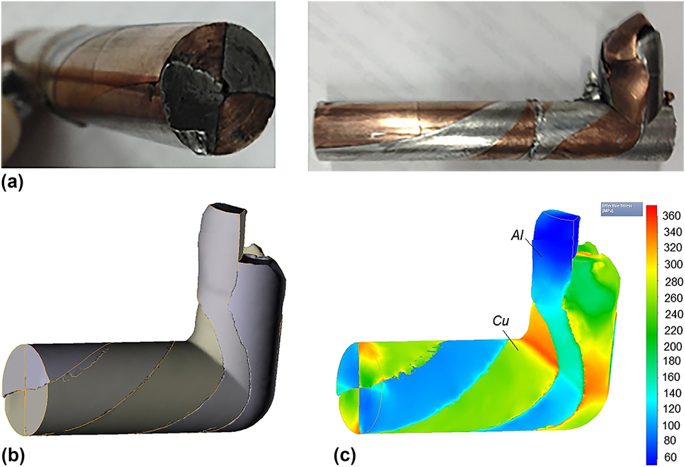
As in the case of a two-piece Al/Cu sample, despite the large magnitude of the coefficient of friction, the four-piece sample exhibited differences in the speed of plastic flow of the pieces placed in the upper and lower parts of the die, see Fig. 5(b). Again, a significant difference in flow stress of the two materials, Fig. 5(c), gave rise to slip along contact surfaces and resulted in nonuniform flow, as proven by simulations. It can be seen that the difference in equivalent stress between aluminum and copper across the shear plane was around 200 MPa.
D. Modeling of separation between the constituent pieces of an ECAP-R processed hybrid
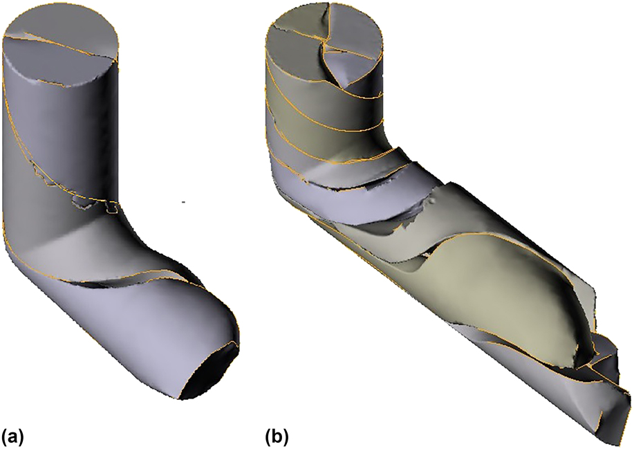
Simulations of the behavior of a two-piece and a four-piece hybrid material show that separation between the constituents occurred at the exit of the ECAP-R die, Fig. 6. This is obviously due to a positive mean stress in the deformation zone. It was shown that even for solid rods processed by conventional ECAP, cracks may appear in materials with low ductility, so that a billet exiting the ECAP die will be fragmented. Reference Lapovok20 The role of back pressure in creating negative mean stress in the deformation zone and preventing the initiation of cracks in the deformation zone at the inner corner of the die is discussed in Ref. Reference Lapovok20. Obviously, separation of nonconnected pieces under the conditions when the mean stress is positive and the hydrostatic pressure negative is even easier. Further important aspects of introducing back pressure in this process are as follows: (i) the possibility to restrict the flow of the constituents of a compound billet in longitudinal direction eliminating the overflow of one of them and (ii) increase of the normal pressure at the interface due to swelling of the components, which will subsequently increase the friction holding the parts together. Therefore, to provide the formation of good cohesion at an interface, design of an ECAP-R die with applied back-pressure is planned. Thus, FE simulations provide a tool for process design ensuring that positive hydrostatic pressure at interfaces between the constituent pieces of an intended hybrid material prevails throughout the process.
Modeling of separation between the constituent pieces of billets as a result of ECAP-R processing. (a) Two-piece hybrid; (b) four-piece hybrid.
E. Forming a cohesive interface
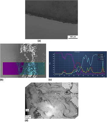
While a positive mean stress spells problems with cohesion between the metals forming a hybrid, good cohesion between them was found in the regions where it had a negative value. Observations were carried out by SEM on samples cut in a vicinity of an interface. Good bonding between the constituents of a hybrid with a discernible intermixing zone of 10–25 μm width, see Fig. 7, was obtained in regions below the middle plane of the billet. Samples cut from such bonded regions and subjected to annealing at 500 °C for 5 min exhibited the formation of a perfect interface of about 6 μm width, Fig. 7(d). Several studies, e.g., Ref. Reference Hug and Bellido22, have shown the existence of an intermetallic layer between copper and aluminum after annealing, with the thickness of the interface layer depending on temperature and duration of heat treatment. This interface layer consists of different phase zones, including Al2Cu, AlCu, Al3Cu4, and Al4Cu9 due to the variation of the Al content across the interface as shown in Ref. Reference Hug and Bellido22. The identification of phases is not within the scope of this article. However, it should be noted that optimization of interface thickness and mechanical properties can be performed by tuning the temperature and duration of the annealing treatment.
Formation of an interface in the region with negative values of the mean stress of an ECAP-R processed Al/Cu hybrid. (a) Al/Cu interface (SEM image); (b) elemental map showing an intermixing zone; (c) line scan across the interface; (d) panoramic SEM image of an interface formed after annealing at 500 °C.

IV. CONCLUSIONS
This article has provided a possible realization of a new paradigm of SPD processing, Reference Bouaziz, Kim and Estrin5,Reference Bachmaier and Pippan8,Reference Raabe, Choi, Li, Kostka, Sauvage, Lecouturier, Hono, Kirchheim, Pippan and Embury9,Reference Beygelzimer, Estrin and Kulagin11 which combines producing a desired inner architecture of a hybrid material with extreme grain refinement in its constituents. The particular engineering solution proposed consists in modifying the standard ECAP process to enable die rotation leading to formation of a helical arrangement of the components of a hybrid material. The most significant outcomes of this work can be summarized as follows.
-
(1) A new SPD process based on ECAP with rotating shear plane (ECAP-R) was developed.
-
(2) The process was studied experimentally on a rig developed for the purpose and also by means of FE simulations for model two-piece and four-piece Cu/Al hybrids.
-
(3) In the upper part of the hybrid close to the top surface of the die, separation of its constituent pieces was observed due to a positive mean stress developing there. This suggests that the process needs to be modified to incorporate back pressure, thus maintaining a negative mean stress, i.e., a positive hydrostatic pressure, during deformation.
-
(4) In other regions, the formation of cohesive interfaces with an element intermixing zone as a result of ECAP-R was observed. Subsequent annealing improved the quality of bonding. This suggests that for obtaining good bonding between the constituents of a hybrid material, processing by ECAP-R should be performed at elevated temperatures.
ACKNOWLEDGMENTS
One of the authors (YE) acknowledges financial support from the Russian Ministry of Education and Science through grant #14.A12.31.0001.