I. INTRODUCTION
An important trend in recent years is to use multidisciplinary modeling and design approaches for complex systems. This is particularly important in life science applications, where combinations of different engineering disciplines enable precise design of lab-on-chip systems. For such systems, rapid and precise thermal control is oftentimes a crucial system requirement, e.g. in lab-on-chip systems for polymerase chain reaction (PCR).
Thermal actuation is done with heating and cooling elements, whereas temperature measurements are done with either contact-based or contact-less devices. Resistive heaters and heating blocks suffer from the dependence on thermal conductivity, heat capacity, and thermal coupling to the environment of microfluidic devices. Contact-based temperature measurement systems require a direct contact to estimate the temperature and suffer from thermal loading of the system under inspection. Furthermore, infrared temperature sensors are limited by the small penetration depth of the interrogating wave inside the material.
The use of microwaves for microfluidic heating applications has been demonstrated by several groups. Fermér et al. [Reference Fermér, Nilsson and Larhed1] were the first to use microwave heating for PCR and Auroux et al. [Reference Auroux, Shah, Booth, Rao, Locascio and Gaitan2] were the first to demonstrate on-chip microwave-based thermocycling for PCR. More recently, several groups have reported work on microwave heating in microfluidics [Reference Orrling, Nilsson, Gullberg and Larhed3–Reference Marchiarullo, Sklavounos, Oh, Poe, Barker and Landers13]. Some of them employ cavities as heating devices [Reference Orrling, Nilsson, Gullberg and Larhed3] that are loaded with a microfluidics chip. Microstrip transmission lines (TLs) [Reference Sklavounos, Marchiarullo, Barker, Landers and Barker5, Reference Kempitiya, Borca-Tasciuc, Mohamed and Hella7] containing fluidic channels in between the signal and ground conductors are the prevalent planar structures reported so far. The use of coplanar waveguide TLs has also been demonstrated [Reference Shah6]. Moreover, most solutions were designed to operate at 2.45 GHz [Reference Fermér, Nilsson and Larhed1, Reference Auroux, Shah, Booth, Rao, Locascio and Gaitan2, Reference Sklavounos, Marchiarullo, Barker, Landers and Barker5, Reference Shaw9–Reference Morgan11, Reference Marchiarullo, Sklavounos, Oh, Poe, Barker and Landers13]. Only Sundaresan et al. [Reference Sundaresan, Polk, Reyes, Rao and Gaitan4] investigated frequencies beyond 15 GHz.
Apart from heating applications, it is possible to use microwaves for temperature measurements of high-water content liquids through the temperature dependency of the dielectric permittivity of water [Reference Ellison14]. Naylon et al. demonstrated temperature estimation by high precision permittivity measurements [Reference Naylon10].
Based on the literature so far, several conclusions can be drawn. Firstly, microwave microfluidic heating research should extend towards different emerging microfluidics platforms such as digital (droplet based) microfluidics. For ease of integration with existing microfluidics platforms, uniplanar heater designs should be considered. Secondly, the notion that heating must be done at 2.45 GHz needs to be re-evaluated in light of the broad availability of low-cost microwave power MMIC's, even into the millimeter wave range, and the different scale of the heating design problem. For heating nanoliter volumes, the optimal choice of operating frequency should follow from a comprehensive analysis of the heating process itself, starting from the known dependency of the complex permittivity of water as documented in [Reference Ellison14]. Of course, the same issues are encountered by the industrial microwave heating community [Reference Kappe15], but the design space for lab-on-a-chip systems is very different. Finally, the use of the same temperature dependency of permittivity should be thoroughly investigated as a mechanism for realizing non-contact temperature sensors for microfluidics.
This paper presents an optimized microwave heater at 20 GHz for easy integration with microfluidics platforms. Our developed device can perform temperature estimation on nanoliter fluid samples with accuracies limited only by the precision of the microwave measurement system, and the accuracy of the permittivity and multi-physics simulation data. Initial heating and temperature estimation results for the design presented in this paper have been presented in [Reference Markovic16]. It was concluded that a power level of 23 dBm at 20 GHz is enough to bring a water droplet to a boiling temperature in a few seconds. In this paper, we present a more comprehensive description of the design process and the measurement approach.
The paper is structured as follows: Section II presents the multi-physics heater design followed by Section III where the measurement setup and the device are presented. In Section IV we will discuss the measurement results and in the last section, conclusions are drawn.
II. MICROWAVE HEATER DESIGN
A) Design discussion
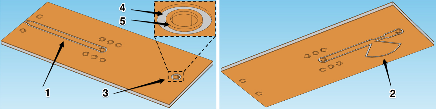
The heater was realized on a 100-μm thick liquid crystal polymer substrate (Rogers UltraLam 3850) with 18 µm thick copper layers and vias. The device consists of three elements: a feeding TL (1), a matching network (2), and a heating element (3) (Fig. 1). The heating element (3) consists of a ring-shaped opening (4) in the top metal fed by a grounded coplanar waveguide (CPW) line on the backside of the substrate (1) (Fig. 1). The via diameter (5) and annular opening (4) width were chosen to be 150 and 50 µm, respectively. The radial electric field in the opening (4) is almost uniform, which will help to achieve uniform heating. A matching network with a radial shunt stub (2) was designed to transform the impedance of the water-loaded open end of the TL to 50 Ω. A feeding TL was added to allow probing of the microwave heater, at a small distance away from the heater.
Heater layout: top view (left) and bottom view (right).

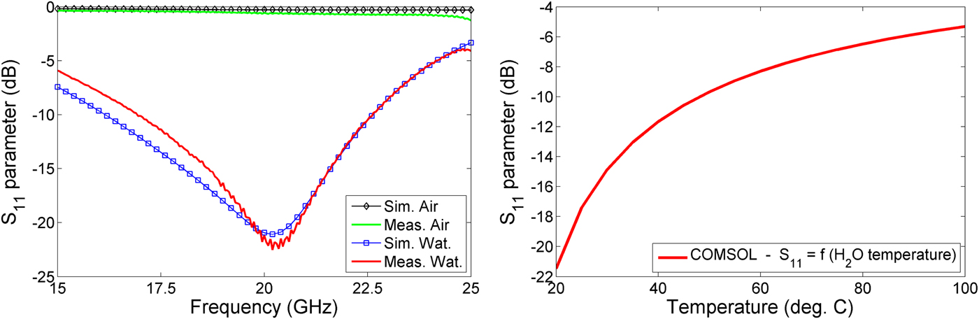
The measured and simulated S-parameters of the unloaded and water-loaded heater obtained from COMSOL are shown in Fig. 2 on the left. It can be noticed that the reflection coefficient is small when the annular opening is loaded with water, and vice versa without water. Moreover, when the temperature of the water is varied, the S-parameter will vary accordingly, allowing the temperature of the sample to be derived under small-signal conditions. This variation on the input reflection was simulated in COMSOL by varying the permittivity of the water sample as per the data in [Reference Markovic16], and is shown in Fig. 2 on the right.
(Left) Simulated and measured S-parameters of the water- and air-loaded microwave heater at 20.5 °C; (right) simulated S-parameters of the microwave heater for different temperatures of the load (water) at 20 GHz.

Based on the simulated and measured S-parameters of the device in Fig. 2, we can also say that the heater is very efficient in the first moments of the heating – up to 50 °C only 10% of the power or less is reflected to the source and 90% or more is being fed to the heating element. At the maximum temperature of interest (95 °C) the device can feed 75% of the power to the heating element. Furthermore, based on the COMSOL simulations we can confirm that the device is not radiating any power. This is due to proper grounding, the absence of strong discontinuities (which tend to produce radiation), and the lateral size of the device being small compared with the free space wavelength.
B) Multi-physics simulation of the heating process
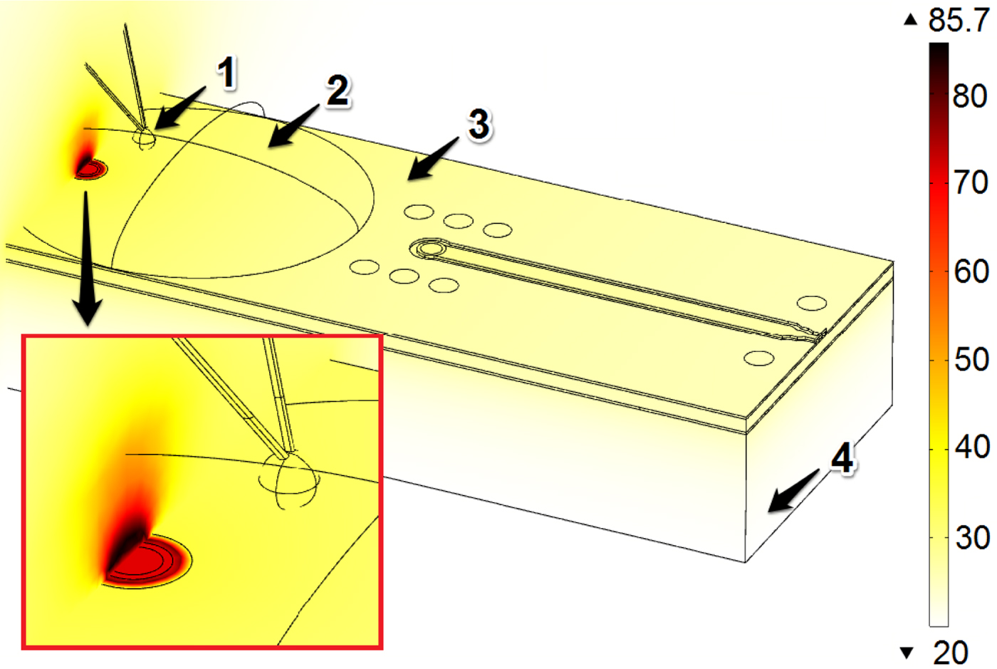
The heating performance of the device in Fig. 1 was analyzed in COMSOL by simultaneously solving Maxwell's and heat transfer equations. As shown in Fig. 3, the heater was placed on a Plexiglas [poly(methyl methacrylate) (PMMA)] plate to avoid contact of the back metallization of the device with the surface of the probe station chuck. Also, the thermocouple was included in the model.
Simulated spatial temperature profile of the water-loaded microwave heater, 1 s after the heating has started, 1 – thermocouple, 2 – water droplet, 3 – microwave heater, 4 – bottom PMMA slab.

The dielectric losses caused by the incident grounded CPW mode were used as a heat source for the (time domain) thermal solver to obtain the temperature profile within the model. As a result of temperature changes, the dielectric properties of the load (water) changed and a new iteration of the EM simulation was performed. Again, new results of the EM solver resulted in a new set of dielectric loss values and so on. In COMSOL, this loop is repeated until the time constraint value is reached or until the system reaches steady state. In this way, we evaluated the transient behavior of the heater during the first 10 s of heating, with a time step of 1 s. A smaller time step did not result in significant changes to the solution. The results shown in Fig. 3 show a relatively uniform temperature profile around the open end of the TL – ring-shaped opening in the top metal layer. It can be also noticed that the temperature profile has high gradients moving away from the heat source, which is to be expected given to the large liquid sample in comparison to the heating element. To reduce these temperature gradients, the liquid sample should be not much larger than the heater size. In our case, we were limited by the lowest possible volume our pipette could dispense. We also needed enough liquid around the heater to be able to measure the temperature with a thermocouple.
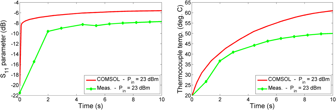
Apart from the microwave heating performance, the COMSOL simulations also yielded insight about where the thermocouple could be placed (Fig. 3) without perturbing the electromagnetic field. On the other hand, we wanted to place the thermocouple as close as possible to the center of the heat source. The result in Fig. 3 clearly shows the temperature difference between the liquid surrounding the heat source and the liquid nearest the thermocouple, illustrating the need for contact-less temperature sensors for lab-on-a-chip applications. The results in Fig. 4 show simulated and measured S-parameters of the heater and the temperature of the thermocouple during the heating process in COMSOL, 1 s after turning on the power source. How we obtained the measured data will be discussed in the next section.
Simulated and measured S-parameter at 20 GHz (left) and temperature profile (right) during heating with 23 dBm input power.

The COMSOL simulations also allowed us to investigate undesired heat losses due to the thermal contact of the heated sample with its surroundings. The results show that thermal energy is lost via the copper, conducting heat towards the cooler environment. For future designs, this suggests the use of thermal isolators (e.g. polytetrafluoroethylene or cyclic olefin copolymer) between the heated water sample and the cooler environment to reduce heat leakage.
C) Measurement setup
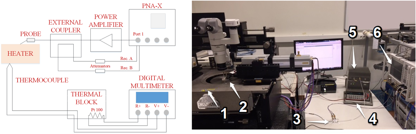
A Keysight PNA-X N5267A, Keysight 83020A high-frequency power amplifier, external coupler and 20 dB attenuators were combined as shown in Fig. 5 and connected to the device using a 150 µm GGB 40A probe.
Schematic diagram (left) and photograph of the measurement setup. On photograph: 1 – Cascade probe station, 2 – GGB Picoprobe, thermocouple and microwave heater, 3 – directional coupler and attenuators, 4 – digital multimeter, 5 – power amplifier, and 6 – Keysight PNA-X.

This setup allows enough power to be generated at the load, while allowing S-parameter measurement by measuring forward and backward waves by the PNA-X's A and B receivers. The GGB probe was calibrated using an impedance standards substrate and a SOL calibration process. Furthermore, a power calibration was performed to allow accurate power excitation of the heater, at the probe tips.
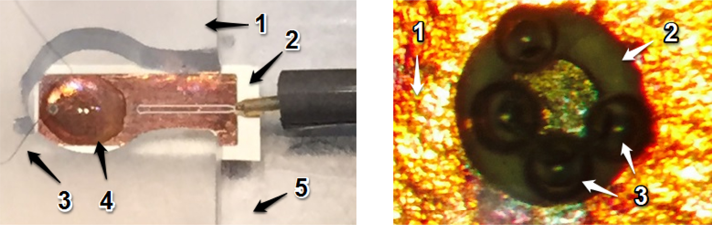
A miniaturized type K thermocouple (Fig. 6) with 25 µm diameter wires was used. This sensor minimizes thermal loading of the device. The Chromel-Cu and Alumel-Cu junctions were kept at a constant temperature between two large Al slabs (thermal block in Fig. 5). Air gaps between the slabs were filled with highly thermally conductive paste to insure uniform temperature. The junction temperature was monitored with a 100 Ohm Pt detector (Pt100 RTD) and the resistance was measured with a digital multimeter (HP 34401A). A 500 nL (smallest possible with available pipette) droplet of water was placed on the device. Fig. 6 shows a close-up of the device during measurement. It is placed between two PMMA slabs held together with screws and placed on the chuck of the probe station.
Shown left: close-up of the heater device during measurement (1 – top PMMA slab, 2 – microwave heater, 3 – thermocouple wires, 4 – water droplet, 5 – bottom PMMA slab); shown on right: microscope image from the top of the TL open end during heating (1 – top copper metal, 2 – via gap, 3 – bubbles).

III. MEASUREMENT RESULTS
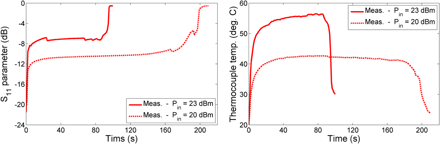
Initially, the device was measured with the setup in Fig. 5 under low power (i.e. non-heating) conditions. The results for the unloaded and water-loaded case are shown in Fig. 2, showing an excellent match between simulation and measurement. After that, the setup was used in the large signal mode to characterize the heating performance of the device. The goal of the measurements was to evaporate a liquid volume of 500 nL with power levels of 20 and 23 dBm at 20 GHz. During the evaporation process, the temperature of the liquid and the reflection coefficient of the heater were recorded every second. The S-parameters of the heater and the measured temperature of the water for both power levels are shown in Fig. 7.
Measurement results for S11 at 20 GHz (left) and thermocouple temperature (right) during heating with 20 and 23 dBm.

Comparing the simulation and measurement data in Fig. 4 (23 dBm case), it can be concluded that the heater performs as expected during the heating process. During the first few seconds of the heating process, the droplet heats rapidly, and due to the high-temperature gradients created near the heater, bubbles are generated as shown in Fig. 6. The flat regions in the data shown in Fig. 7 correspond to the liquid evaporation phase and heating of the water further away from the open end of the TL. The S-parameters at the end of the heating process correspond to the impedance of the thin layer of boiling water and air above it.
The difference between the simulated and measured S-parameter data for the first 10 s of heating can be explained by the bubbles that were generated during the measurements, and were not present in the simulation. When bubbles are present, the open end of the TL sees a higher impedance, translating to a higher reflection coefficient. When bubbles start to detach from the surface, the impedance seen at the load experiences “jumps” each time a bubble is released.
From the observed lower heating rate and steady state temperature compared with simulation, we conclude that not all thermal loss paths towards the environment are fully taken into account by the COMSOL model.
As stated in Section IIA, the heating efficiency reduces during the heating process due to the change in the permittivity of water during heating, causing increased impedance mismatch, which the data in Fig. 7 indeed clearly shows. This effect also allows us to indirectly determine the temperature of the water in the immediate vicinity of the open ended TL. The simulation data allows us to estimate a high heating rate of around 65 °C/s in the region of the gap of the open end, during the first second of the heating process (Fig. 7).
IV. CONCLUSION
In this paper, we have reported an optimized microwave heater that uses 23 dBm of power at 20 GHz to heat a liquid sample of 500 nL in 4 s to 100 °C. We have also exploited the idea of temperature sensing with microwaves and reported possibilities and limitations of this technique with our microwave heater. Furthermore, we have conducted thorough multi-physics analysis of the microwave heater in COMSOL to guide design improvements.
ACKNOWLEDGEMENTS
The authors wish to thank the Research Foundation – Flanders (FWO) and the KU Leuven (C2 project μ2BIO) for their research funding.
 Tomislav Markovic received the B.Sc. and M.Sc. degrees in Electrical Engineering and Information Technology from the University of Zagreb, Zagreb, Croatia, in 2011 and 2013, respectively. During bachelor and master studies he worked on design of a six-port junction and broadband measurement system for fast waveforms. He is currently working towards the Ph.D. degree at KU Leuven, div. ESAT-TELEMIC, in the field of microwave and mm-wave life science research.
 Song Liu received the Ph.D. degree in Electrical Engineering from KU Leuven, Leuven, Belgium, in 2016. From 2014 to 2015, he spent 6 months with the RF Technology Division, National Institute of Standards and Technology, Boulder, CO, USA, under the support of KU Leuven. His current research interests include RF power amplifier design, microwave biomedical applications, VNA calibration, and material characterization. Dr. Liu was one of the recipients of the ARFTG Roger Pollard Student Fellowship in 2013 and the MTT-S Graduate Fellowship in 2014.
 Ilja Ocket received the Ph.D. degree in Electrical Engineering from KU Leuven, Leuven, Belgium, in 2009. He has been with imec and the KU Leuven (div. ESAT-TELEMIC) since 1999 where he has been involved in research on millimeter wave components and systems. He is now active in the areas of 79 and 140 GHz CMOS radar sensors, microwave, and millimeter wave metrology and application development for the life sciences, and (sub)-millimeter wave plastic waveguide integration.
 Bart Nauwelaers received the Ph.D. degree in Electrical Engineering from the KU Leuven in 1988. He also received the Master's degree in Design of Telecommunication Systems from Télécom ParisTech, Paris, France. Since 1981, he has been with the Department of Electrical Engineering, KU Leuven, where he has been involved in research on microwave antennas, passive components, interconnects, microwave integrated circuits and MMICs, linear and non-linear device modeling, MEMS, and wireless communications. Dr. Nauwelaers is the former chair of IEEE AP/MTT-Benelux and past chair of URSI-Benelux.