NOMENCLATURE
- cwt
-
wing-tip mean chord
- C mθ
-
aerodynamic moment coefficient
- D aero
-
hinge aerodynamic damping
- D θ
-
hinge structural damping
- f
-
natural frequency
- H
-
gust gradient
- I θaero
-
aerodynamics moment of inertia
- I θ wt
-
wing tip's moment of inertia
- K aero
-
hinge aerodynamic stiffness
- K θ
-
hinge structural stiffness
- Lg
-
gust length
- Swt
-
wing-tip area
- V
-
flight speed
- Wg
-
gust velocity
- W g0
-
peak of gust velocity
- W ref
-
reference gust velocity
- α WT
-
wing-tip angle-of-attack
- Λ
-
hinge orientation angle
- θ
-
wing-tip folding angle
- ξ n
-
modal damping
- Φ
-
Von Karman power spectral density
- ψ n
-
random phase
- CFD
-
Computational Fluid Dynamics
- FWT
-
Folding Wing-Tip
- PSD
-
Power Spectral Density
- RMS
-
Root Mean Square
- WRBM
-
Wing-Root Bending Moment
Symbols
Abbreviations
1.0 INTRODUCTION
Much effort has been made to design aircraft to optimize fuel consumption through reduction of aerodynamic drag. A sizable contribution to the overall drag is lift-induced drag, which could be reduced by increasing the wing span, but such a design solution has well defined limits imposed by the maximum aircraft dimensions allowed at airports and also the increase in bending moments along the wing. A possible solution to the first issue is the use of folding wings that can be employed on the ground similar to the retractable wings used on aircraft-carrier-borne aircraft. An example of this approach relevant to civil applications is the latest version of the B-777, which will have a folding wing capability to be activated during taxing to and from the gates. The inclusion of such a design feature raises the question as to whether such a folding device could also be used to enable load reduction on the aircraft during the flight.
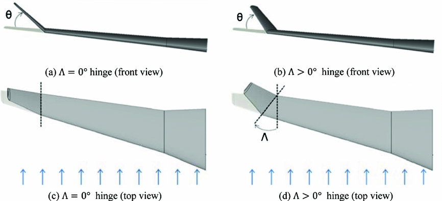
This work is aimed at studying the benefits of using a flexible wing-fold device for load alleviation and considering how it would be implemented on civil jet aircraft. The main idea consists of introducing a hinge in order to allow the wing tips to rotate, as shown in Fig. 1. The orientation of the hinge line relative to the airflow is a key parameter to enable successful load alleviation. When the hinge line is not parallel to the free stream, but is rotated outboard as in Fig. 1(b,d), folding the wing-tip up introduces a decrease in the local angle-of-attack. Knowing the hinge orientation Λ and the angle of rotation of the wing-tip θ, the local angle-of-attack Δα WT can be given by:
 $$\begin{equation}
{\alpha _{WT}} = - {\tan ^{ - 1}}\left( {\tan \theta \sin \Lambda } \right)
\end{equation}$$
Hinge orientations.

Such an effect implies that using a non-zero hinge angle provides a means to reduce the loads acting on the wing, leading to the possibility of achieving a wing-tip extension with limited or even minimal impact on wing weight.
A series of numerical simulations are performed on a representative civil aircraft model to demonstrate the benefits of load reduction on static and dynamic gust loads through the use of a folding wing-tip.
2.0 AEROELASTIC MODEL
2.1 Structural modelling
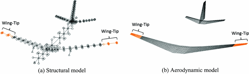
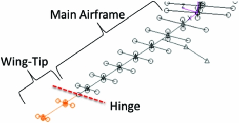
Figure 2 shows the baseline aeroelastic model used for the analyses, which was a modified version of the FFAST aeroelastic model(Reference Khodaparast and Cooper1) of a representative civil jet aircraft whose structure was modelled using a “stick” model with lumped masses. The main objective was to investigate the possibility of having an aircraft configuration that enables a higher aspect ratio, and consequent reduction in the induced drag, whilst limiting the increase in load (especially in terms of wing-bending moment) experienced by the aircraft, thus keeping the structure as light as possible. The baseline model without wing tips (Fig. 2 was considered as the reference to evaluate the effect of using the folding wing-tips, also shown in Fig. 2, which were attached to the structure using a flexible hinge, giving an increase in span of 25% compared to the baseline. Figure 3 shows a detailed view of the structural model with the attached wing-tip device.
Aeroelastic model showing baseline model and wing-tips.

Folding wing-tip modelling detail.

The hinge was modelled by constraining two coincident nodes, one belonging to the main airframe and the other to the wing-tip, to have the same translations but free to have different relative rotations with respect to the pre-defined hinge axis. The linear structural model did not account for the wing span shortening effect due to the wing-tip rotations, but this effect was considered to be negligible.
To investigate the effects of such a hinge device on the aircraft response, several structural configurations were analysed by varying both the orientation of the hinge with respect to the free stream direction, 0° and 25°, and the weight of each wing-tip. A 943kg mass configuration was defined in order to have the same structural configuration used in a previous work(Reference Hodigere Siddaramaiah, Calderon, Cooper and Wilson2), while the other configurations were introduced to examine the effect of varying the wing-tip mass. Several values for the spring torsional stiffness and damping were also investigated for each configuration, starting from a fixed hinge up to an almost free hinge (a small stiffness was used to avoid numerical singularities).
2.2 Aerodynamic modelling
The doublet lattice panel method(Reference Albano and Rodden3,Reference Rodden and Johnson4) was used for the aerodynamic model, which is based upon linear unsteady potential flow theory, making the assumptions of inviscid, irrotational, compressible and attached flow, subject to small angle-of-attack or side slip. As a consequence, nonlinear aerodynamic effects such as flow separations, shocks, turbulence and boundary layers as well as aerodynamic drag were not accounted for. Only the lift forces and pitching moment, defined for each aerodynamic panel, were considered in the aerodynamic load estimation. A further limitation due to the small angle-of-attack or side slip assumption is that the aerodynamic forces do not to change their direction as a function of the actual deformation of the structure and wing-tip deflection. The aerodynamic forces were defined with respect to the local normal direction of each panel by modifying the modulus, but not the orientation, of each aerodynamic force as a function of the local deformation.
The above approximations are general acceptable when applied to conventional aircraft structures subject to small deformations, and indeed the doublet lattice method has been the aeroelastic workhorse of the aerospace industry for over 40 years. Within an industrial environment, aircraft load estimation requires the computation many tens of thousands of load cases and as a consequence, high-fidelity Computational Fluid Dynamics (CFD)-based analyses cannot be extensively employed. Furthermore, unsteady gust analysis using CFD models is still a novel methodology and is very much an immature approach for industrial applications; consequently the doublet lattice method is still a standard tool within the industrial community for aircraft load estimation.
Although modelling of the follower aerodynamic forces effects might be required when considering folding wing-tips, the results reported in the following sections show that the wing-tip deflections are in general quite limited. Consequently, it has been considered acceptable to use the doublet lattice approach for this preliminary investigation to make a qualitative analysis of the effect of the folding wing-tip on aircraft load and dynamic response. A high-fidelity estimation of the aerodynamic properties of such device is well beyond the purpose of this work and will be tackled in future research activities along with wind-tunnel testing.
3.0 AEROELASTIC ANALYSES
In order to investigate the effects of the wing-tip device with different parameter settings, several aeroelastic analyses have been made for different structural and flight configurations.
3.1 Static trim solution
A static aeroelastic analysis was performed using Nastran SOL 144. A 1-g load case was considered with the aircraft operating at M = 0.6 at 25,000ft, equivalent to a dynamic pressure of 9.47KPa. The aircraft was left free to pitch and plunge in order to achieve the trim configuration by considering the angle-of-attack and the elevator deflection as trim variables.
3.2 Flutter analysis
The dynamic stability of the aeroelastic system was verified through a flutter analysis performed using the PK and PKNL methods in Nastran SOL 145. The following analyses were performed:
-
• A matched configuration analysis where the number of Mach was fixed to a cruise value of M = 0.82 and the velocity changes, from 241.9m/s to 274.83m/s, as a function of the altitude from 4,500ft to 50,000ft.
-
• Three unmatched configuration analyses where the velocity was swept from 100m/s to 900m/s at the following flight configurations: M = 0.4 at altitude 20,000ft, M = 0.6 at altitude 25,000ft and M = 0.8 at altitude 30,000ft. The authors are aware that the flight speeds considered for the unmatched analyses were beyond the normal flight envelope limits; nevertheless they were used in the flutter calculation with the purpose of highlighting the qualitative trend of the aircraft flutter behaviour by varying the different design parameters.
The selected modal base included modes in the frequency range 0–12Hz with a modal damping of 2%, while the rigid-body modes were removed from the analysis since they have little damping and oscillate around the zero damping level, often causing a false flutter-speed reading.
3.3 “1-cosine” gust response analysis
In this study, the aircraft was subjected to a discrete gust in the form of a “1-cosine” gust, using Nastran SOL 146 such that the velocity profile acted in a vertical direction normal to the path of the aircraft.
The gust profile was defined as (5)
 $$\begin{equation}
{w_g}\left( t \right) = \frac{{{w_{g0}}}}{2}\left( {1 - \cos \frac{{2\pi Vt}}{{{L_{g\ }}}}} \right),
\end{equation}$$
where Lg is the gust length (twice the gust gradient H), V is the flight speed in TAS and wg0 is peak gust velocity. The latter defined by
 $$\begin{equation}
{w_{g0}} = {w_{{\rm{ref}}}}{\left( {\frac{H}{{106.17}}} \right)^{\frac{1}{6}}},
\end{equation}$$
where wref was varied linearly from 13.4m/s EAS at 15,000 ft to 7.9m/s EAS at 50,000ft, based on the FAA Federal Aviation and EASA regulations(Reference Albano and Rodden3). At the investigated flight altitude of 25,000ft and Mach number of M=0.6, the gust reference velocity is 11.48m/s EAS, while the gust lengths were varied between 18m and 214m. For this analysis, a value of Δf = 0.04166Hz was selected as frequency resolution and 600 frequency increments were defined to cover the frequency range from 0–25Hz.
3.4 Continuous turbulence response analysis
A continuous turbulence gust case was also investigated. According FAA Federal Aviation and EASA Regulations(Reference Albano and Rodden3), for the same flight point of the deterministic gust analyses, the reference turbulence intensity is taken as 24.08m/s TAS. A Von Karman Power Spectral Density (PSD) of the atmospheric turbulence with a scale of turbulence of 2,500ft was considered.
For this analysis a value of Δf = 0.005Hz was selected as frequency resolution and 5,000 frequency increments were defined to cover the frequency range from 0–25Hz. The Root Mean Square (RMS) of the response (area of the PSD) was considered as the means to determine the effect of the various hinge parameters.
4.0 RESULTS
4.1 Static aeroelastic trim solution
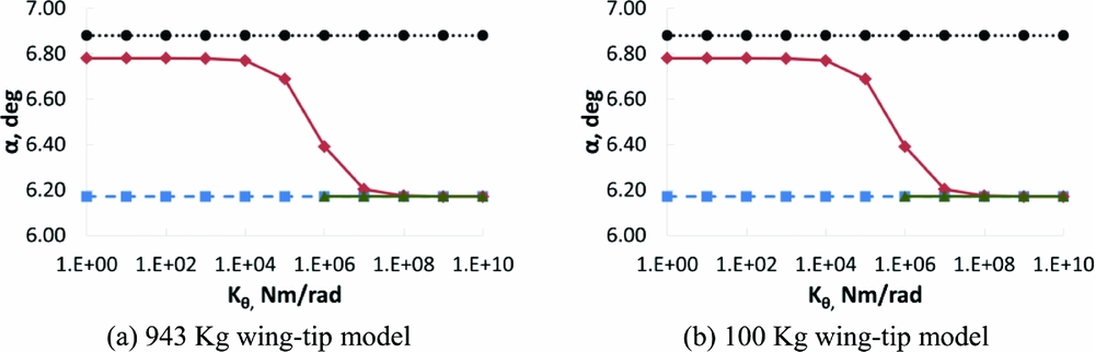
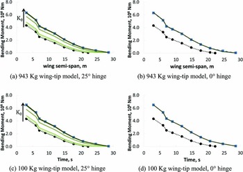
In this section, the static aeroelastic longitudinal trim solution of the extended-wing-tip aircraft is shown. Figures 4 and 5 show the trim angle-of-attack and the bending moment distribution along the spanwise direction, respectively, for the 0° and 25° flexible hinges. The hinge stiffness corresponds to the rotational stiffness about the axis that runs through the hinge line, which was varied between 1.E0Nm/rad and 1.E10Nm/rad such that the highest stiffness considered in this study corresponded to a fixed hinge.
Static trim angle-of-attack. (
 fixed-hinge model;
 baseline model;
 25° hinge model;
 0° hinge model).

Wing bending moment distribution. (
 fixed-hinge mode;
 baseline model;
 flexible-hinge model) Kθ = (1.E0, 1.E5, 1.E6, 1.E7, 1.E8) Nm/rad).

The results show a number of differences in the response between the baseline model and the model with folding wing-tips. There were almost no differences between the static responses of the models with different wing-tip weights, as would be expected for a static aeroelastic results; however, the response of the model was greatly influenced by the orientation of the hinge.
-
• 0° hinge model:
The introduction of a 0° elastic hinge did not introduce any difference in the response with respect to the fixed-hinge model. The deflection of the wing-tip did not generate any variation in the local angle-of-attack since the folding motion does not have any pitching component, meaning that the aerodynamic forces were the same as for the fixed-hinge model. Using a hinge spring with a stiffness lower than 1.E06Nm/rad led to a divergence solution due to very high rotation of the outer wing, and was thus ignored.
-
• 25° hinge model:
The baseline and the fixed-hinge models represented the lower and upper boundaries of the elastic hinge model's response. The lower the hinge stiffness, the higher the wing-tip rotation and so the lower the lift given by the rotated wing-tip. The wing-tip rotation gave a decrease in the lift contribution, thus reducing the load (bending moment and vertical shear) experienced by the aircraft. The more the wing-tip was rotated, the higher the required trim angle-of-attack since the inner wing had to generate more lift to balance the aircraft's weight. It is possible to use a very low structural stiffness for the hinge since the wing-tip behaviour is characterized also by an ‘aerodynamic stiffness’ contribution. The most efficient load alleviation was achieved for the 100kg wing-tip model with a spring stiffness of 1.E0Nm/rad, where the Wing-Root Bending Moment (WRBM) was just 4.36% higher than the baseline model with no wing tip. For this case, the wing-tip rotation of θ = 26.67° led to a decrease in the local angle-of-attack of Δα = –11.98°, which corresponded to an effective angle-of-attack of α = –5.20°, giving a global angle-of-attack at the trim configuration of α = 6.78°.
4.2 Flutter analysis
A flutter analysis was performed for different flight configurations, hinge directions, wing-tip weight and spring stiffness; no hinge damping was defined on the model in order to have a more conservative evaluation of the stability boundaries.
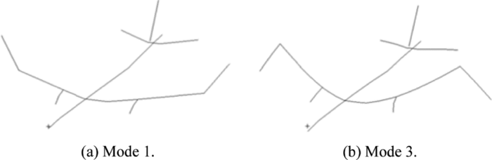
The normal mode analysis showed that when the hinge stiffness was higher than 1.E07Nm/rad, the mode shapes and modal frequencies were almost the same as those of the fixed-hinge model. The use of a more flexible spring gave changes in the modal characteristics affecting mainly the lower frequencies (< 4Hz). For hinge stiffness values lower than 1.E04Nm/rad, the first two flexible modes represented a local symmetric and antisymmetric wing-tip folding, respectively, while the other modes involved interactions between the wing tip and the main airframe.
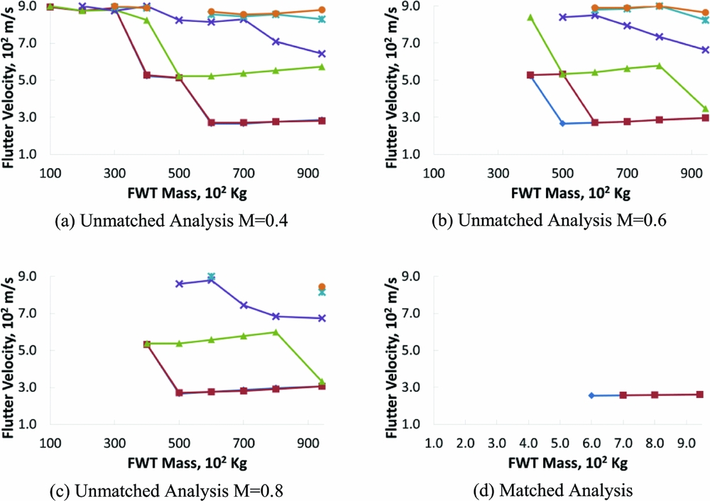
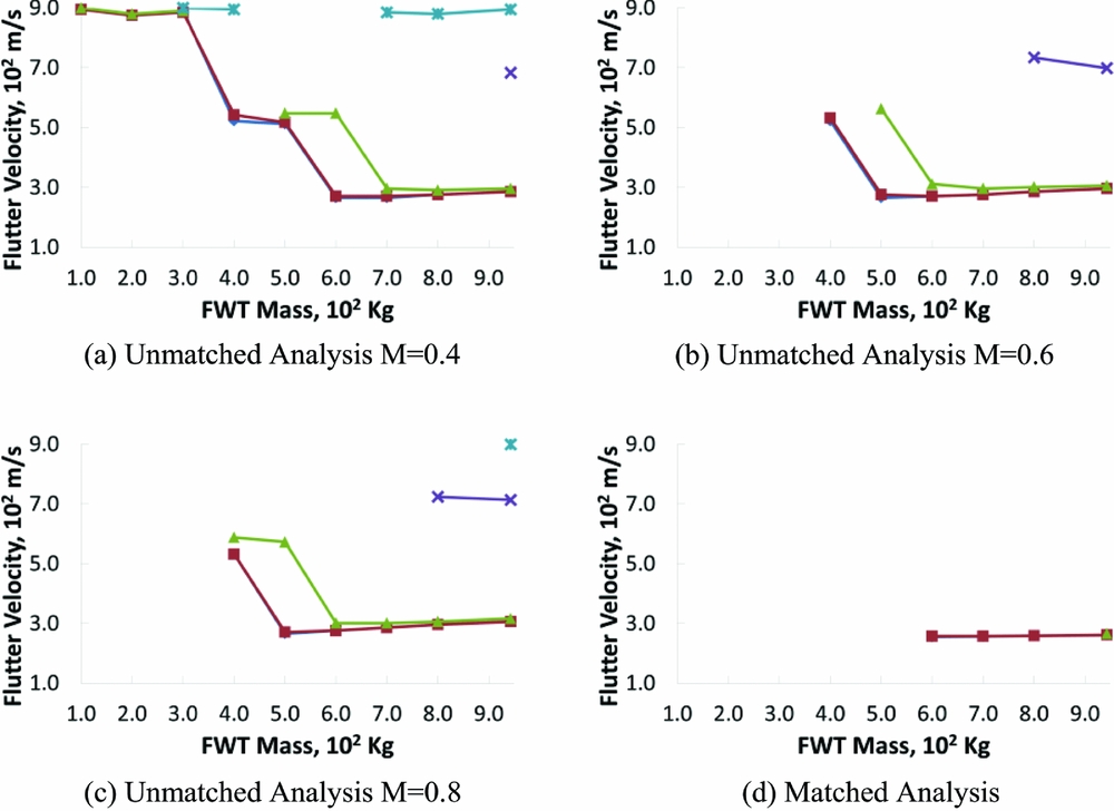
Figures 6 and 7 show the stability boundaries of the wing-tip models over a range of hinge stiffness and wing-tip mass values.
-
• 25° hinge:
The flutter analyses showed how high spring-stiffness values and low wing-tip mass were beneficial for the stability of the aeroelastic system leading to high flutter velocities. The wing-tip mass was the most influential design parameter affecting the flutter speed; in fact for values lower than 300kg, the sensitivity of the flutter speed with respect to the spring stiffness was negligible.
Figures 7(a),(b) and 8 show the V–g and V–ω plots for an unmatched analysis (M = 0.6 at 25,000ft) and the main components of the critical eigenvector for the 943kg wing-tip with a spring stiffness of 1.E0Nm/rad; the flutter mechanism is driven by a coupling of the first symmetric wing-tip mode with the first symmetric bending mode of the wing with the wing-tips shifted in phase of 180°. This coupling is also enhanced by the fact that the bending of the wing-tip introduces a variation of the local angle-of-attack which does not occur for the 0° hinge model. When a heavy wing-tip is employed (M > 400kg), increasing the spring stiffness is beneficial. For spring stiffness higher than 1.E06 Nm/rad, the local wing-tips modes were not present any more, leading to a variation of the flutter mechanism and to higher flutter speeds with respect to the more flexible case.
Figure 7(c) and (d) show the same V–g and V–ω plots as in the previous case, but now for a 100kg wing-tip with a spring stiffness of 1.E0Nm/rad. It can be seen in Fig. 7(c) that the two poles that are highly damped have the main components of the complex eigenvectors given by the first two wing-tip modes. The wing-tip modes that caused the instability problems for the previous case are now more stable, as the velocity increased due to the increment of the aerodynamic stiffness and reduction in the inertia of the wing-tips with respect to the 943kg model. Figure 7(d) shows that the poles, that represent the local modes of the wing-tips, had a frequency growing almost linearly with the speed (true for K θ < 1.E06Nm/rad). The higher the flight speed, the larger the contribution of the aerodynamic stiffness on the hinge global stiffness (structural and aerodynamic), leading to an increase in the wing-tip mode natural frequency. This linear trend indicates that the local wing-tip modes tended to remain mostly uncoupled from the main airframe modes when a low wing-tip mass and low hinge-spring stiffness were defined. The local wing-tip dynamic response can be modelled, as a first approximation, as a single degree of freedom system such that
(4)Assuming I θaero ≪ I θwt and K θ < 1.E06 (i.e. K θ ≪ K aero), then defining the aerodynamic stiffness as $$\begin{eqnarray}
({I_{\theta wt}} &+& {I_{\theta {\rm{aero}}}})\ddot{\theta } + ({D_\theta } + {D_{{\rm{aero}}}})\dot{\theta } + \left( {{K_\theta } + {K_{{\rm{aero}}}}} \right)\theta = 0\;{{\rm{I}}_{{\rm{\theta wt}}}}{\rm{\ddot{\theta }}} + \left( {{{\rm{D}}_{\rm{\theta }}} + {{\rm{D}}_{{\rm{aero}}}}} \right){\rm{\dot{\theta }}}\nonumber\\
&& + {{\rm{K}}_{{\rm{aero}}}}{\rm{\theta }} = 0\end{eqnarray}$$
${K_{{\rm{aero}}}} = \textstyle\frac{1}{2}\rho {V^2}{s_{wt}}{c_{wt}}{C_{m\theta }}\sin \Lambda $
, the natural frequency of the wing-tip is given by
(5)
$$\begin{equation}
f \approx \frac{1}{{\begin{array}{@{}*{1}{c}@{}} {2\pi }\\ \ \end{array}}}\sqrt {\frac{{{K_{{\rm{aero}}}}\left( {1 - {\xi _n}^2} \right)}}{{{I_{\theta wt}}}}} = \frac{V}{{\begin{array}{@{}*{1}{c}@{}} {2\pi }\\ \ \end{array}}}\sqrt {\frac{{\frac{1}{2}\rho {s_{wt}}{c_{wt}}C{m_\theta }\sin \Lambda \left( {1 - {\xi _n}^2} \right)}}{{{I_{\theta wt}}}}}
\end{equation}$$
-
• 0° hinge:
All the analyses that were undertaken, both with matched and unmatched flight points, exhibited an overall stable behaviour across the entire range of the analysed flight points with very high flutter velocities. Four hinge stiffness values were considered: 1.E06Nm/rad, 1.E07Nm/rad, 1.E08Nm/rad, 1.E12Nm/rad. For the two stiffer springs, the flutter speeds had the same trend of the 25° hinge model with the same stiffness values, as in Fig. 6, the hinge being nearly rigid. A change in the stability of the system for the 0° hinge model was observed when the two softer springs were defined. Even though statically the wing-tip deflections did not generate any variation in the aerodynamic forces, from a dynamic point they introduced an aerodynamic damping contribution which was beneficial for the flutter behaviour.



25° hinge model, flutter velocities. (
 Kθ = 1.E0Nm/rad;
 Kθ = 1.E5Nm/rad;
 Kθ = 1.E6Nm/rad;
 Kθ = 1.E7Nm/rad;
 Kθ = 1.E8Nm/rad;
 Kθ = 1.E12Nm/rad)

25° hinge model, Kθ = 1.E0Nm/rad – unmatched analysis V–g V–ω plots.

Main modal components of the critical eigenvector.

4.2.1 Hinge damping effect
Further investigations were made to determine the effect on the stability boundaries of the model by introducing a local damper element on the hinge. These analyses were carried out only for the 25° hinge model with a spring stiffness of 1.E0Nm/rad, varying the value of the damping element from 1.E03Nms/rad to 1.E06Nms/rad.
The flutter speeds are shown in Fig. 9 and as might be expected, the flutter velocities were higher for larger values of the damping element. For Dθ = 1.E06Nms/rad the first two modes (which correspond to the local wing-tip folding modes) are critically damped and possess a zero frequency for all the velocities of the analysed flight envelope.
25° hinge model, flutter velocities—hinge damping effects (Kθ = 1.E0Nm/rad). (
 Dθ = 1.E0Nms/rad;
 Dθ = 1.E3Nms/rad;
 Dθ = 1.E4Nms/rad;
 Dθ = 1.E5Nms/rad;
 Dθ = 1.E6Nms/rad)

4.3 “1-cosine” gust response analysis
4.3.1 Hinge stiffness effect
In this section, the dynamic response of the model with the folding wing tips during a gust event was considered for a linear spring added to the hinge with no local damper. Figure 10 shows the maximum and minimum incremental WRBMs for the 100kg and 943kg wing-tip models with 0° and 25° hinge over a range of gust lengths:
-
• The baseline model is subjected to the lowest loads, both in terms of minimum and maximum peaks.
-
• 0° hinge:
943kg wing-tip model – the introduction of the folding wing-tips enabled alleviation of the maximum positive loads with respect to the fixed-hinge model, but they still remained higher than those of the baseline model. When the spring stiffness was 1.E06Nm/rad, the negative WRBM was lower than that of the baseline model for the shorter gust lengths, but higher for longer gust lengths.
100kg wing-tip model – the loads remained almost the same as the fixed-hinge model with varying hinge stiffness, as for the static analysis. This behaviour is due to the fact that the variation of the aerodynamic forces given by the wing-tip motion did not affect the model response and the inertial forces were negligible.
-
• 25° hinge:
943kg wing-tip model – the maximum positive loads were experienced by the fixed-hinge model. For the flexible-hinge model, there was a decrease in the positive loads trend with decreasing spring stiffness. However, the load alleviation effect given by the folding wing-tip was not enough to reach the loads experienced by the baseline model. When the spring stiffness had values lower than 1.E05Nm/rad, the absolute negative loads became even higher than the fixed-hinge model.
100kg wing-tip model – it can be seen that both for the maximum and the minimum loads decreased with a reduction in the hinge spring stiffness.
-
• For all configurations, the model behaved as a fixed-hinge model for spring stiffness higher than Kθ = 1.E07Nm/rad.
Wing bending moment envelopes. (
 fixed-hinge model;
 baseline model;
 flexible-hinge model Kθ = (1.E0, 1.E5, 1.E6, 1.E7, 1.E8) Nm/rad).

4.3.2 Wing-tip mass effect
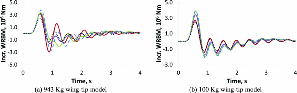
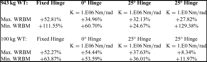
The differences between the response of the 943kg and 100kg wing-tip models can be explained by looking at the time histories of the wing-root bending moment for the various configurations. For this investigation, a spring stiffness of Kθ = 1.E06Nm/rad was considered for the 0° hinge, while Kθ = 1.E0Nm/rad and Kθ = 1.E06Nm/rad were considered for the 25° hinge case. In both cases, there was no local damping element on the hinge. Only one gust length was considered, Lg = 127m, which was the one that generally produced the highest wing-root loads. Figure 11 and Table 1 show the time histories of the WRBM and the variation of the maximum and minimum loads with respect to the baseline model for all configurations:
-
• 0° hinge:
943kg wing-tip model – the folding tip device was not able to alleviate the loads enough to reach the WRBM of the baseline model. Figure 12(a) shows that the forces generated by the folding tip device were primarily given by the inertial contribution. The aerodynamic forces were lower since the wing-tip rotation did not introduce any variation on the local angle-of-attack; they were mainly due to the aerodynamic damping effect. There could be some alleviation effect, but this was generally unpredictable since the wing-tip behaved as an oscillating mass rather than a passive aerodynamic load-alleviation system.
100kg wing-tip model – this case did not provide much load alleviation effect and the time history of the WRBM was almost unchanged with respect to the fixed-hinge model. Figure 13(a) shows that the inertial forces due to the wing-tip motion were negligible with respect to the aerodynamic forces, which were slightly influenced by the wing-tip folding. Consequently, the global forces generated by the folding device were almost the same of the ones for the fixed-hinge model.
-
• 25° hinge:
943kg wing-tip model – for both the hinge stiffness values, the folding-tip device was not able to alleviate the loads enough to reach the WRBM levels of the baseline model. Although the first positive peak for the flexible hinges was always lower with respect to those from the fixed-hinge model, this is not true for the first negative peak, which got worse for the more flexible hinge, Kθ = 1.E0Nm/rad. Figure 12(c) and (f) show that the increment of first negative peak for the flexible-hinge model was given by the folding wing-tip having a phase shift of almost 180° with respect to the WRBM trend.
As consequence of this delay, the folding device generated a WRBM contribution that was in phase with the global WRBM, which therefore was increased. Figure 12(b) and (e) show that, for Kθ = 1.E06Nm/rad, this phase shift is lower, so a load alleviation effect was achieved. This phase shift between the global WRBM and the wing-tip rotation is the key element for enhancing the load alleviation effect. In order to optimize the load alleviation, the global WRBM and the hinge deflection should be in phase at least for the first two peaks of the gust response.
100kg wing-tip model – for both the hinge stiffness values, the folding-tip device was able to alleviate the load with respect to the fixed-hinge model, especially for the more flexible hinge case where the WRBM was very close to that of the baseline model. Figure 13(e) and (f) show that there was a small phase shift between the first WRBM peak and the folding angle, which was due to a very low contribution of the inertial forces. Figure 13(c) show that the aerodynamic forces generated by the wing-tip rotation balanced almost perfectly the load given by the gust when a light wing-tip and a very flexible hinge spring were defined. This behaviour confirms the efficiency in the load alleviation since the wing-tip was almost unloaded during the gust event and so its contribution to the WRBM was relatively small. The maximum folding angle achieved with such configuration was around 12.08°.
Wing-root bending moment time histories. (
 fixed-hinge model;
 baseline model;
 0° hinge model Kθ = 1.E6Nm/rad;
 25° hinge model Kθ = 1.E6Nm/rad;
 25° hinge model Kθ = 1.E0Nm/rad)

943kg wing-tip model. Upper plots: aerodynamic and inertial load contributions of the wing tip to the global WRBM. Lower plots: global WRBM VS wing-tip folding angle (normalised).

100kg wing-tip model. Upper plots: Aerodynamic and inertial load contributions of the wing tip to the global WRBM. Lower plots: Global WRBM VS wing-tip folding angle (normalised).

Variation of the maximum and minimum WRBM with respect to the baseline model

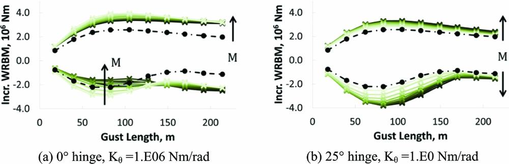
The dynamic responses of the models with a 0° hinge and 1.E06Nm/rad spring stiffness, and with a 25° hinge and 1.E0Nm/rad spring stiffness, were considered for several wing-tip mass configurations, ranging from 100kg to 943kg. Figure 14 shows the maximum and minimum incremental WRBMs over a range of gust lengths:
-
• 0° hinge:
By increasing the wing-tip mass there was a slight load alleviation of the positive peaks due to an inertial relief effect, but no conclusion could be made for the negative loads which exhibited an irregular trend.
-
• 25° hinge:
A significant reduction for both positive and negative loads was achieved with a reduction in the wing-tip mass. Such an effect was more pronounced for the negative loads which were strongly affected by the wing-tip response delay and was minimized for low wing-tip masses.
WRBM envelopes for different mass configuration.
 baseline model;
 flexible-hinge model M = (100, 200, 300, 400, 500, 600, 700, 800, 943kg).

4.3.3 Hinge damping effect
Further investigation was also made into the effect of adding a discrete damping element on hinge together with a spring. A hinge spring stiffness of 1.E06Nm/rad for the 0° hinge model was used while 1.E0Nm/rad and 1.E06Nm/rad stiffness were used for the 25° hinge. The damping was varied between 1.E03Nms/rad and 1.E06Nms/rad. Figure 15 shows the maximum and minimum incremental WRBMs for the 0° and 25° hinges over a range of gust lengths for:
-
• 0° hinge:
943kg wing-tip model – the introduction of a lumped damping element did not generate any load alleviation effect on the response of the model; the higher the damping, the greater the WRBM for the flexible hinge, and these values were close to that of the fixed-hinge model.
100kg wing-tip model – the WRBM was only slightly affected by the value of the damping element and remained almost unchanged with respect to that of the fixed-hinge model.
-
• 25° hinge:
943kg and 100kg wing-tip models – for the maximum loads, increasing the damping value led to the WRBM trends tending to those of the fixed-hinge model. For the minimum loads, the presence of a discrete damper sometimes generated loads which were higher than those of the fixed-hinge model. This effect is due to the increasing delay between the WRBM and the folding angle given by the damping element.
WRBM envelopes for different hinge damping values. (
 fixed-hinge model;
 baseline model;
 flexible-hinge model Dθ = (1.E3, 1.E4, 1.E5, 1.E6Nms/rad).

4.4 Continuous turbulence response analysis
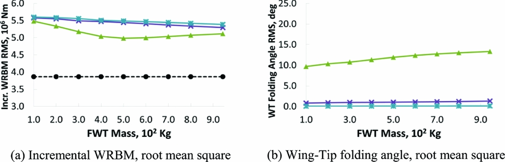
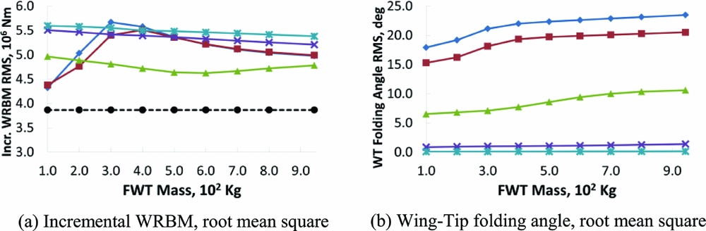
In this section, the dynamic response of the aircraft model with the folding wing-tips due to continuous turbulence was analysed. Figures 16 and 17 show the RMS values of the WRBM and the wing-tip folding angle. As before, several wing-tip mass, hinge spring stiffness and hinge angles were considered.
-
• Again, the baseline model was characterized by to the smallest load level, as expected.
-
• 0° hinge:
The highest loads were experienced by the fixed-hinge model. Some load alleviation was achieved when a more flexible spring, 1.E06Nm/rad, was used. For the unswept hinge, such alleviation effects were due to the aerodynamic damping and inertial forces generated by the wing-tip motion.
-
• 25° hinge:
The highest loads were experienced by the fixed-hinge model for which a slight reduction of the loads was achieved by increasing the wing-tip mass. A reduction of the loads with respect to the fixed-hinge case, was achieved with 1.E06Nm/rad hinge spring stiffness, also in this case changing the folding device inertial properties introduced only a slight variation of the loads. However, when the more flexible hinge case was considered, changing the wing-tip mass led to a significant influence in the WRBM. Minimum loads were achieved with a 100kg wing-tip configuration and a substantial change in the loads was observed for mass cases between 200kg and 400kg, with even higher loads compared to the fixed-hinge case; higher mass values led to a slight reduction of the loads, which were still significantly higher than those of the baseline model.
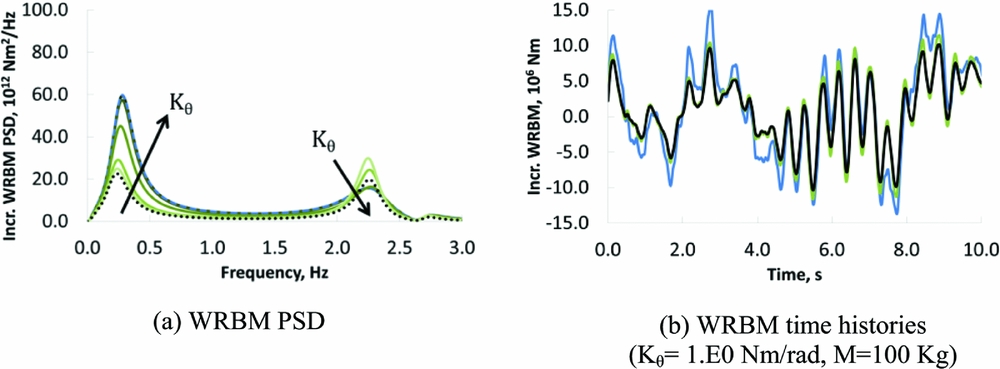
A better insight of such dynamic response is given by the power spectral density trends shown in Figs 18 and 19. Figure 18(a) shows the power spectral density of the WRBM for the baseline model, the fixed-hinge case and the flexible-hinge cases for different hinge stiffness values and 100kg of wing-tip mass. The higher energy content of the aircraft frequency response is observed around 0.25Hz and 2.23Hz, which represents respectively the short period and the first wing-bending mode frequencies. The introduction of a flexible hinge enabled the energy content of the short period peak to decrease while the first wing-bending mode peak increased, nevertheless this led to an overall reduction of RMS value of the WRBM.
0° hinge model, continuous turbulence RMS analysis. (
 baseline model;
 Kθ = 1.E6Nm/rad;
 Kθ = 1.E7Nm/rad;
 Kθ = 1.E8Nm/rad).

25° hinge model, hinge model, continuous turbulence RMS analysis. (
 baseline model;
 Kθ = 1.E0Nm/rad;
 Kθ=1.E5Nm/rad;
 Kθ=1.E6Nm/rad;
 Kθ=1.E7Nm/rad;
 Kθ=1.E8Nm/rad).

25° Wing-root bending moment PSD and time histories – hinge stiffness effect. (
 fixed-hinge model;
 baseline model;
 flexible-hinge model Kθ = (1.E0, 1.E5, 1.E6, 1.E7, 1.E8) Nm/rad and M = 100kg).

25° Wing-root bending moment PSD and time histories – wing-tip mass effect. (
 baseline model;
 flexible-hinge model M = (100, 200, 300, 400, 500, 600, 700, 800, 943kg and Kθ= 1.E0Nm/rad).

Time histories were produced by running time-domain gust analyses using a gust profile time signal defined by combining a series of harmonic signals randomly shifted in phase as(Reference Hoblit6)
 $$\begin{equation}
{w_g}\left( t \right) = \mathop \sum \limits_{n = 1}^{{N_{{\rm{sample}}}}} 2\sqrt {\Phi \left( {{f_n}} \right)\Delta {f_n}} \cos \left( {2\pi {f_n}t + {\psi _n}} \right),
\end{equation}$$
where Φ(fn ) is the value of the Von Karman PSD at a given frequency, Δfn is the frequency step defined for the PSD discretization and ψ n is the random phase. Such a random gust signal has same energy distribution, in frequency, of the Von Karman spectrum.
Figure 18(b) shows the time histories of the WRBM for the baseline model, the fixed-hinge model and the flexible-hinge model with a spring stiffness of 1.E0Nm/rad showing that the root loads of the latter case were very close to the baseline-model loads due to the efficient load alleviation capability.
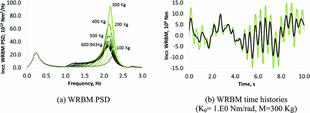
In Fig. 19(a), the power spectral density trend of the WRBM for different wing-tip mass and a fixed-hinge spring stiffness of 1.E0Nm/rad are shown. The second PSD peak around the first wing-bending mode frequency was strongly influenced by the wing-tip mass variation. The highest values were obtained for the 300kg and 400kg configurations, confirming the trend reported in Fig. 17(a). No variations were observed for the first peak. Figure 19(b) shows the time histories of the WRBM when a 300kg wing-tip and a 1.E0Nm/rad spring were defined and a significant increment in the loads with respect to the baseline model was observed; however, the results for 100kg tip were still close to the baseline model.
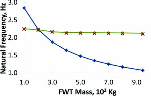
Figure 20 shows the variation of the first wing-tip and first wing-bending mode frequencies when a hinge spring stiffness of 1.E0Nm/rad and several mass cases were considered. Such modal frequencies account for the aeroelastic effects and were evaluated by investigating the frequencies of those modes from a matched flutter analyses at a Mach value of 0.6, an altitude of 25,000ft and a flight speed of 185.8m/s. The excitation introduced by the random gust led, as expected, to peaks of the WRBM PSD for frequencies close to the first wing-bending moment for all the mass cases. It has been demonstrated that the wing-tip could be considered a quasi-uncoupled dynamic system, with respect to the main airframe, when low spring stiffness and low wing-tip mass were defined.
First wing-tip and first wing-bending modes aeroelastic natural frequencies at M = 0.6, h = 25,000ft and V=185.8m/s. (
 1st wing-tip mode;
 1st wing-bending mode;
 WRBM PSD peak frequency).

Figure 20 shows that for a wing-tip mass of 100kg, the wing-tip mode has a frequency of 2.84Hz, which is higher than that of the wing-bending mode, 2.26Hz, allowing the wing tip to be fast enough to react to the gust loads. The latter were giving a peak of the wing-root banding moment PSD at 2.25Hz. A wing-tip mass of 200kg led to a wing-tip mode frequency of 2.23Hz and a wing-bending mode frequency of 2.22Hz, which means that the frequency giving a peak of the WRBM PSD was close to the aeroelastic resonant frequency of the wing-tip. This effect led to a consequent a phase shift of the response of folding device with respect to the external excitation of 90°. For the 300kg and 400kg mass cases, the wing-tip natural frequency was even lower leading to a higher phase shift up to 180° and the PSD peak was now at a frequency higher than the wing-tip resonance. The increment of the wing-tip phase shift resulted in an increment of the loads experienced by the aircraft. Higher-mass cases led to lower PSD peaks around the frequency of the first wing-tip bending mode, but also to increments of the PSD in lower frequency bands, indicating a stronger inertial coupling between the main airframe and the wing-tip.
For all the structural configurations, the loads due to continuous turbulence were always higher than the baseline model; however, the results for a low-stiffness, low-mass wing-tip showed loads only slightly lower. It should be noted that the responses are very sensitive to the wing-tip mass values. Such an effect was due to the fact the Von Karman gust profile excited higher frequency components of the aeroelastic system with respect to the “1-cosine” excitation.
Such a trend highlighted a limitation in the load alleviation performance of the proposed hinge device when higher-frequency excitations had to be alleviated. It is so fundamental to design the folding device such that the first wing-tip mode aeroelastic frequency is high enough to allow an efficient alleviation of the external gust loads. This can be achieved either by reducing the wing-tip mass or by increasing the hinge sweep angle, which would reflect into an increment of the aerodynamic stiffness of the wing tip.
5.0 CONCLUSIONS
A preliminary investigation on the effects of using folding wing-tips as a load alleviation device was performed using a numerical aeroelastic model of a typical commercial jet aircraft. A wing-tip device was connected to the wings with an elastic hinge, increasing the span by 25%, and the effect of varying the hinge stiffness, damping, hinge orientation and wing-tip mass on the static loads, gusts loads and flutter behaviour was investigated. All results were related to the loads acting on a baseline model which consisted of the aircraft without wing-tips.
The static analyses showed that the response of the model was highly influenced by the orientation of the hinge and that no load alleviation effect was observed for the streamwise hinge case. The greater the hinge angle with respect to the free stream direction and the lower the hinge spring stiffness and wing-tip mass, the greater the load alleviation due to the resulting nose-down twist of the wing-tip. For the case considered in the static trim analyses, a 25° hinge with low hinge stiffness gave wing-root loads that were reduced by nearly 30% compared to the rigid-hinge case and gave loads of just 4.36% higher than the reference model with no wing-tips, despite the total span increasing by 25%.
From the flutter analyses we observed that, when a 25° hinge was defined, a low wing-tip mass was beneficial for the aeroelastic stability both for flexible and fixed hinges. A significant reduction in the flutter speed was observed when a flexible hinge with a high wing-tip mass was defined. The 0° hinge model was instead characterized by very high flutter speeds for all the wing-tip mass hinge spring combinations.
The deterministic gust response analyses highlighted that it was possible to obtain significant load reductions with a swept hinge angle, a reduced wing-tip weight and a low hinge spring stiffness. Detailed studies showed how the interactions between the inertial, elastic and aerodynamic forces worked favourably in order to enhance the load alleviation capability.
The random gust analyses confirmed that good load alleviation could be achieved with a swept hinge, low wing-tip mass and very small hinge-spring stiffness. However, a higher sensitivity of the load alleviation capabilities with respect to the wing-tip mass was observed.
Through proper design of the wing-tip device, it will be possible to increase the wing aspect ratio with little, if any, increase in the internal loads experienced by the aircraft, leading to better aerodynamic efficiency, or simply to reduce the loads and hence the weight on existing platforms. Further work is required to improve the modelling and the design of the hinge device and to develop an experimental prototype.
ACKNOWLEDGEMENTS
The research leading to these results has received funding from the European Community's Marie Curie Initial Training Network (ITN) on Aircraft Loads Prediction using Enhanced Simulation (ALPES) FP7-PEOPLE-ITN-GA-2013-607911 and also the Royal Academy of Engineering. The partners in the ALPES ITN are the University of Bristol, Siemens PLM Software and Airbus Operations Ltd.