I. INTRODUCTION
The sudden growth of wireless internet for high data rate communication has fostered great attention toward the design of compact antennas. Different types of designs catering to various user requirements and multiband applications have been reported in the literature [Reference Chen1–Reference Li, Li and Yi19]. A small planar antenna with L-shaped shorted wire for triple-band application reported in [Reference Jan and Tseng2]. A dual wide band G-shaped slotted antenna proposed in [Reference Kang, Yin, Li, Huang and Zheng3]. A triband U-shaped monopole antenna proposed for WiMAX and WLAN in [Reference Li, Yan and Zhang4]. The various slotted multiband antennas reported in [Reference Song and Jiao5–Reference Lai, Chiu and Chen11]. These designs, however, have complex structures which make them difficult to integrate with WLAN systems. Planar antennas have the advantage of easy integration with active circuits. In this paper, we present asymmetric coplanar strip (ACS) inverted L-fed dual-band antenna with modified ground structure. The resulting antenna operates at two different bands in which 2.4 GHz used for WLAN and 5.8 GHz for WLAN/RFID application. The ground modification in the form of inverted L which reduces the ground dimensions much comparing with existing geometries. The exciting strip also in the form of inverted L, so overall dimension is about 35 × 5.7 mm2.
In this paper, the prime focus on miniaturization of the proposed design comparing with existing variants. An inverted L and F ACS-fed geometry is proposed for WLAN in [Reference Askarali, Sreenath, Sujith, Dinesh, Krishna and Anandan12–Reference Deepu, Sujith, Mridula, Aanandan, Vasudevan and Monahan14]. A similar kind of inverted L-fed geometry with multiple L branches for multi-band operation is proposed in [Reference Liu, Wang and Qin15]. However, those designs investigated in the recent literature have larger size than our current proposal. The feeding mechanism of an antenna is a crucial factor as far as the compactness is taken into account. Normally the feed structure consumes much of the overall dimension of the antenna. In this design, a compact and effective feeding technique is employed. The ACS feed used here has all the advantage of a uniplanar feed along with compactness. This feeding mechanism is analogous to the coplanar waveguide (CPW) feed structure except that the ACS feed has a single lateral ground plane compared to the twin lateral plane strips in the CPW feed structure. The overall size of the antenna reduced about half comparing with CPW-fed antenna.
II. PROPOSED ANTENNA CONFIGURATION
Figure 1 shows the geometry and prototype of the asymmetric coplanar inverted L-fed proposed antenna having length Ls and width Lsw. The feed of proposed antenna is designed using standard design equations of ACS [Reference Simons16, Reference Garg, Bhartia and Bahl20]. The ground plane dimensions of the antenna are optimized by iteration for good impedance matching. The antenna is designed and printed on an FR4 epoxy substrate having dielectric constant 4.4 and thickness 0.8 mm. It has to be noted that the overall antenna dimensions (Table 1) in terms of area is greatly reduced in the case of the proposed antenna using the ACS feed since it uses only a single lateral ground plane.
(a) Geometry of proposed antenna and its prototype (b) side view.

The percentage reduction of area is almost about 50% when compares with similar CPW-fed antennas because it is using single lateral ground plane comparing with twin lateral ground plane in the CPW. So ACS-fed antennas are the promising candidates for the future generation antennas.
Figure. 2 shows the design evolution of the proposed antenna. Initially started from a CPW-fed C-shaped strip-fed geometry and finally we arrived on the proposed ACS L-fed design with miniature size. Figure 2 shows the comparison of return loss characteristics of the proposed antenna with its possible variants. From Fig. 2 we can identify the changes and size reduction when the design development phase of the proposed antenna.
(a) Design evolution of proposed antenna, (b) simulated return loss results.
The design equations for the perfect matching of impedance are given below:
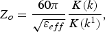 $$Z_o=\displaystyle{{60\pi } \over {\sqrt {\varepsilon _{eff} } }}\displaystyle{{K\lpar k\rpar } \over {K\lpar k^1 \rpar }}\comma \; $$
where from Fig. 1(b)
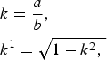 $$\eqalign{& k=\displaystyle{a \over b}\comma \; \cr & k^1=\sqrt {1 - k^2\comma \; } }$$
and K(k)/K(k 1) is the elliptical integral of first kind which is given by
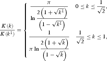 $$\displaystyle{{K\lpar k\rpar } \over {K\lpar k^1 \rpar }}=\left\{{\matrix{ {\displaystyle{\pi \over {\ln \displaystyle{{2\left({1+\sqrt {k^1 } } \right)} \over {\left({1 - \sqrt {k^1 } } \right)}}}}} & {0 \leq k \leq \displaystyle{1 \over {\sqrt 2 }}\comma \; } \cr {\displaystyle{1 \over {\pi \ln \displaystyle{{2\left({1+\sqrt k } \right)} \over {\left({1 - \sqrt k } \right)}}}}} & {\displaystyle{1 \over {\sqrt 2 }} \leq k \leq 1\comma \; } \cr } } \right.$$
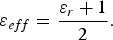 $$\varepsilon _{eff}=\displaystyle{{\varepsilon _r+1} \over 2}.$$
III. RESULTS AND DISCUSSION
The simulated, parametric study and measured results of the proposed antenna have also been observed. The measured and simulated results of return loss characteristics for optimized set of antenna parameters are presented in Fig. 3. From the simulated results it is found that the proposed antenna yield dual-band resonance centered at 2.45 and 5.8 GHz which covers IEEE 802.11 WLAN bands 2.4 GHz (2.4–2.48 GHz) and 5.8 GHz (5.725–5.825 GHz) which is useful for RFID applications. The proposed antenna fabricated on an FR4 substrate by simple chemical etching and screen-printing process. The measurement is carried out using HP8510C vector network analyzer. The measured results show good agreement of dual-band operation of the proposed antenna which ranges 2.42–2.5 GHz in lower frequency band and 5.7–5.95 GHz in upper frequency band
Comparison between simulated and measured return loss.
Parameters of the proposed antenna.

.
The simulated current distribution of the proposed antenna shown in Fig. 4, which shows the current perturbation of the proposed design is more in the ground plane for lower band of resonance and in upper band of resonance current through exciting strip is prompting. The parametric analysis of the proposed antenna by varying width of the ground plane Lw and leg length of exciting strip L1 are shown in Figs. 5 and 6, respectively. The ground width has great influence on the lower frequency band 2.4 GHz. Here it is found that when the width of ground plane increases the lower resonance tends to shift and goes on decreasing. The optimum results obtained on the Lw = 4 mm. The parametric study on changing the value of leg of exciting strip L2 also carried out. It is clear that L2 has an effect on upper resonance and optimum performance obtained when L2 = 6 mm. So the parameters can be used for tuning the proposed antenna in different nearby applications
Current distribution of proposed antenna (a) 2.4 GHz and (b) 5.8 GHz.
Effect of ground plane width of the proposed antenna.
Effect of variation on leg length (L2) of inverted L exciting strip.
.
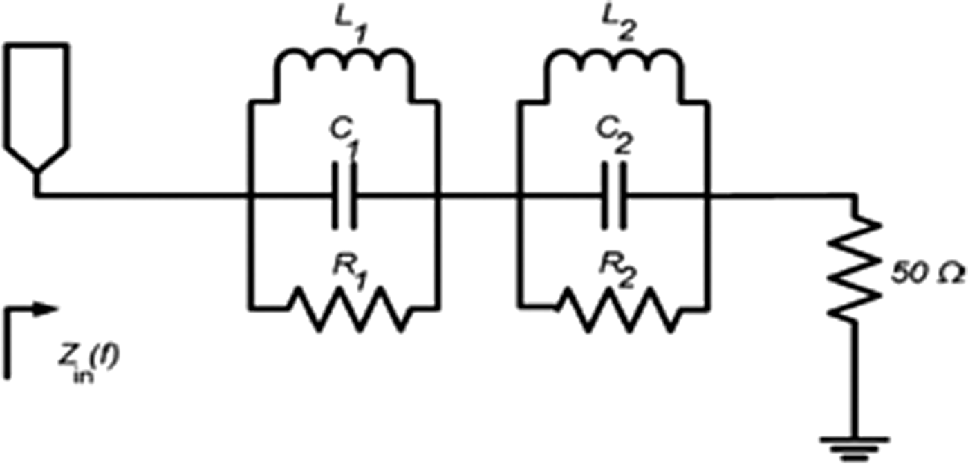
The simple RLC series lumped equivalent model for the proposed antenna for the dual band of resonance shown in Fig. 7. The basic circuit parameters are obtained from designed equations and simulated by mentor Graphics IE3D modua. This analysis carried out by large number of iterations and data fitting, finally obtained an optimized circuit parameters shown in Table 2. For obtaining the equivalent circuit extracts R and L values from IE3D modua for each resonance and cascaded to form the complete equivalent circuit. The comparison between the simulated and lumped equivalent modal of the proposed antenna shown in Fig. 8, which shows good conformity between both results
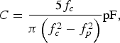 $$C=\displaystyle{{5f_c } \over {\pi \left({f_c^2 - f_p^2 } \right)}}{\rm pF\comma \; }$$
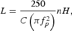 $$L=\displaystyle{{250} \over {C\left({\pi f_p^2 } \right)}}nH\comma \; $$
 $$R=\displaystyle{{2Z_0 } \over {\sqrt {\displaystyle{1 \over {S_{11} \lpar f\rpar ^2 }} - \lpar 2Z_0 \lpar fC - \displaystyle{1 \over {wL}}\rpar \rpar ^2 - 1} }}\Omega s.$$
Lumped RLC equivalent model of proposed antenna.
Comparison between simulated and lumped equivalent model.
Calculated values of equivalent circuit lumped elements.

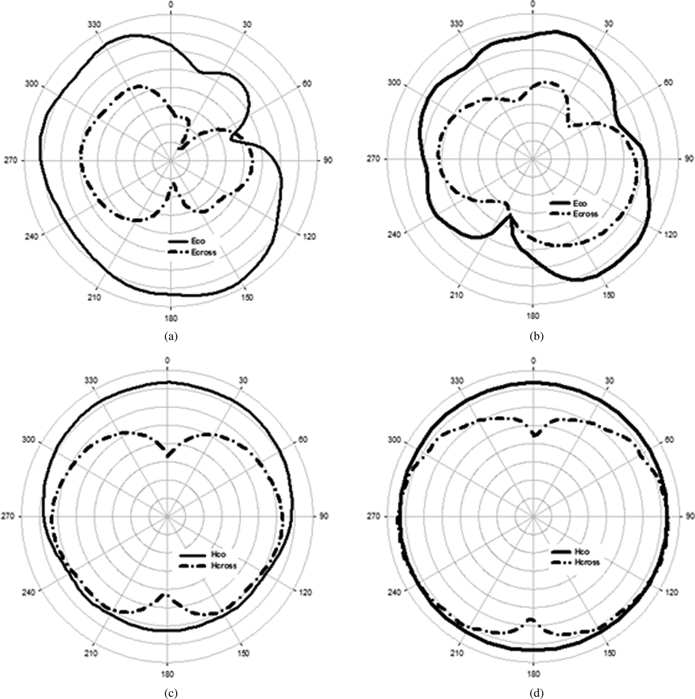
The measured radiation patterns of the E- and H-planes for 2.4 and 5.8 GHz are given in Fig. 9. The results show good and omnidirectional radiation pattern at the H-plane and bidirectional patterns at the E-plane. The small asymmetry in the patterns is because of asymmetry in the proposed antenna feeding configuration. The polarization of the antenna is also experimentally determined and it is found that antenna is polarized along the X-axis for dual band of operation. The cross-polarization level of the proposed antenna is minimum comparing with co-polarization levels
Measured radiation patterns of the proposed antenna (a) E-plane at 2.4 GHz, (b) E-plane at 5.8 GHz, (c) H-plane at 2.4 GHz, and (d) H-plane at 5.8 GHz.
.
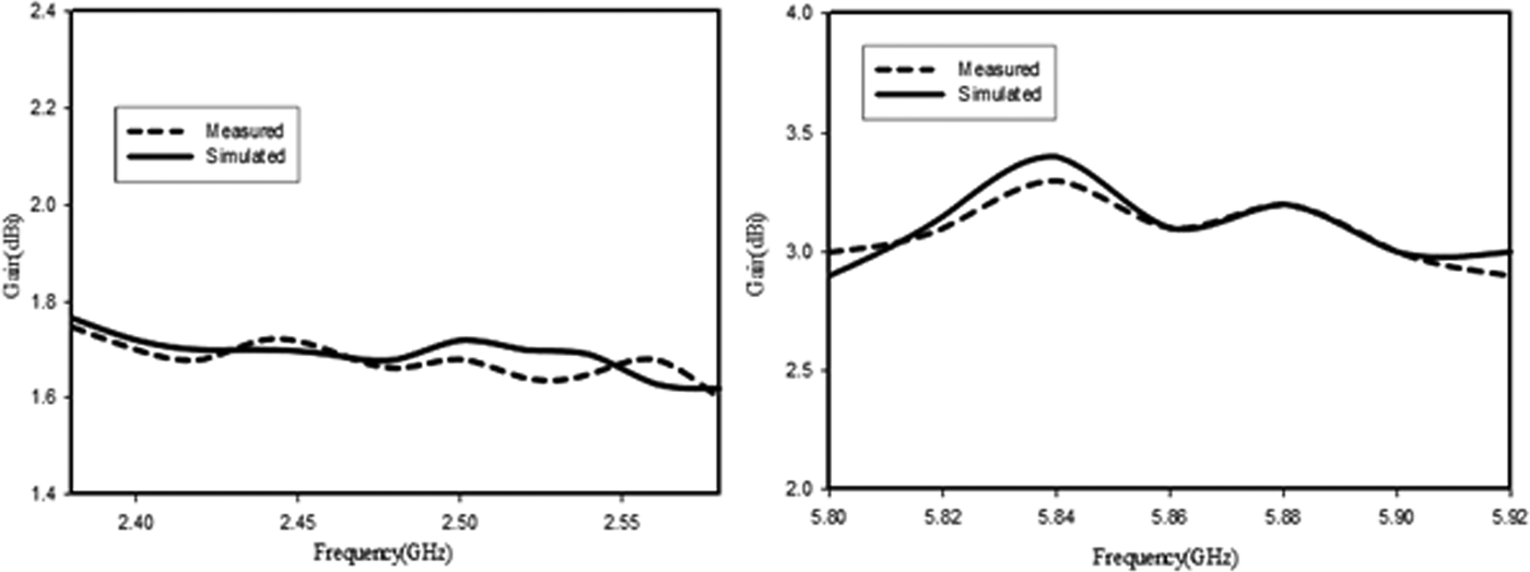
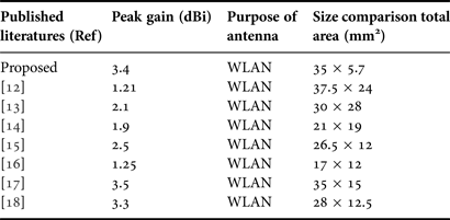
The comparison between area and gain of the proposed antenna with some of the published literatures is shown in Table 3. Here it is observed that the proposed structure has prevailing profile reduction comparing with the existing ACS-fed multiband WLAN antennas. The gain characteristics also shows good agreement with existing geometries. The proposed designs yield peak gain of 1.6 dBi at lower band and 3.4 dBi at upper band of resonance, which is shown in Fig. 10.
Measured and simulated gain of the proposed antenna at lower frequency band and upper frequency band.
Comparison between size and gain of proposed and existing literatures.
IV. CONCLUSION
In this paper, a novel compact ACS-fed dual-band monopole antenna for WLAN/RFID applications is presented. The proposed antenna has compact size (35 × 5.7 mm2) and moderate gain for multiband performance. Its simple geometry, compact size, symmetrical radiation pattern, and good electrical performance make the proposed geometry effective for use in wireless gadgets. Therefore, the proposed antenna is the useful candidate for WLAN applications.
ACKNOWLEDGEMENT
The authors are gratefully acknowledge University Grant Commission for the technical and financial support.
K. A. Ansal received his B. Tech degree in Electronics and Communication Engineering from Mahatma Gandhi University, Kottayam, Kerala in 2007, and M.E. degree in Communication Systems from Anna University Chennai, India in 2011. He is currently working toward Ph.D. degree at School of Engineering and Technology, Pondicherry University (Central University), Puducherry, India. He has authored 11 journals and conference papers. His research interests include microwave and millimeter wave antennas, planar antennas with DGS and EBG, and mobile base station antennas. He is a member of the IEEE and IAENG.
T. Shanmuganatham received his B.E. degree in Electronics and Communication Engineering from the University of Madras, M.E. degree in Communication Systems from Madurai Kamaraj University, and Ph.D. (Gold Medal) in the area of Antennas from the National Institute of Technology, Tiruchirappalli, India under the guidance of Dr. S. Raghavan. He has 15 years of teaching experience in various reputed Engineering colleges such as SSN College of Engineering, National Institute of Technology and Science. Presently, he is working as an Assistant Professor in the Department of Electronics Engineering, School of Engineering & Technology, Pondicherry University, Pondicherry. His research interest includes microwave/millimeter-wave circuits and devices, microwave integrated circuits, and antennas. He has published 125 research papers in various national and international journals and conferences. He is a member of IEEE, Life Member of IETE, Institution of Engineers, CSI, Society of EMC, OSI, ILA, ISI, and ISTE.