1. Introduction
Hybrid machining tools have been proposed as an alternative solution for high-efficient machining in aerospace, aviation, automobile, ship building, and other high-end manufacturing fields thanks to their conceptual merits of high rigidity and good dynamics [Reference Amanullah, Murshiduzzaman and Khan1–Reference Liu and Huang3]. This proposition has been gradually exemplified by the commercial success of Eco-speed [Reference Hennes and Staimer4–Reference Ruiz, Campa, Roldán-Paraponiaris, Altuzarra and Pinto6], Tricept [Reference Jose and Scott7], Exechon [Reference Neumann8], and other parallel spindle heads [Reference Wang, Wu, Wang, Liu and Yu9]. More recently, the authors proposed a new 5-DOF (DOF: degree of freedom) hybrid machining tool composed of a 2R1T (T: translational; R: rotational) redundantly actuated parallel module and a 2T serial module. The conceptual design, the kinematics, and the stiffness analysis have been carried out in our previous studies, which has preliminarily confirmed its potential in machining complex structural components [Reference Fang, Tang and Zhang10, Reference Jiang, Chi, Fang, Tang and Zhang11]. Before it can be used for high-efficient machining, an in-depth research on its numerical control (NC) system design, especially the smooth toolpath interpolation needs to be carried out.
As to the smooth toolpath interpolation, most of the interpolation methods are based on linear algorithms. These interpolation methods are developed for traditional serial machine tools with stack-up open chain; thus, they cannot be directly used for the toolpath smoothing of hybrid machine tools [Reference Wang, Wu, Wang and Liu12]. Consequently, there is an emerging demand for developing a specific smooth toolpath interpolation method suitable for a hybrid machining tools. However, the development of a specific hybrid machining tools used smooth toolpath interpolation method is not an easy task. The reason may lie in two aspects. On the one hand, G01 commands generated by CAM need to be smoothed to eliminate the tangential discontinuities at corners. On the other hand, because of the nonlinear mapping relationship between the operation space and the joint space of hybrid machine tools, the actual velocity of the tool tip will produce a nonlinear fluctuation. Therefore, an applicable smooth toolpath interpolation method for hybrid machine tools must solve the following two critical problems: trajectory control and velocity control.
As indicated by the existing studies [Reference Shi, Qingzhen and Wang13–Reference Wu, Zhou, Tang and Chen15], trajectory control is an effective way to improve machining quality and machining efficiency. The interpolation algorithm is an important issue of the trajectory control. From the aspect of curve fitting method, the interpolation algorithm can be roughly divided into linear interpolation algorithm and parametric curve interpolation algorithm. Following the above two algorithms, many scholars devoted great efforts to improve the trajectory control accuracy. For clarity, a literature review is depicted in Table I.
Literature review.

As shown in Table I, a linear interpolation algorithm is to determine the interpolation step according to the velocity and the interpolation period, so as to realize the linear densification of the interpolation points. For example, Sencer et al. [Reference Sencer, Kakinuma and Yamada16, Reference Tajima and Sencer17] proposed a linear interpolation of tool orientation on spherical surface in synch with the tool tip. As a result, the surface roughness and the contouring accuracy of workpiece are improved by 10% and 75%, respectively. Wang et al. [Reference Wang, Li, Si, Yuan and Liu18] proposed a linear interpolation to obtain the interpolated toolpath of S-shaped workpiece based on the cutter location data. The maximum geometric deviation of the machined S-shaped workpiece is reduced by 25.3%. Wang et al. [Reference Wang, Wu and Wang19] proposed a linear interpolation of the tool-axis vector in a new plane determined by the initial tool-axis vector and the end tool-axis vector. As a result, 97.5% of the detection points reached the test standard of maximum error less than 0.2 mm and roughness values Ra less than 1.6 μm. In addition, Ni et al. [Reference Ni, Zhang, Sun, Wang and Sun20] proposed an improved linear interpolation method in the joint space. Based on the improved linear interpolation method, a set of S-shape workpieces machining test were carried out. The experimental results demonstrate that the maximum geometric deviation of the machined workpiece is only 0.086 mm.
Generally, there are two ways to formulate the parametric curve interpolation algorithm: (1) the first way is to adopt constant parameter increment and (2) the second way is to use arc length increment. Compared with the second way, the first way is relatively simple and is mostly used in early studies [Reference Shpitalni, Koren and Lo21]. However, the relationship between the parameter increments and the corresponding arc length increment of a parametric curve is nonlinear. This may lead to significant fluctuation in velocity. Aiming at this problem, parametric curve interpolation with arc length increment was proposed, which obtains the trajectory interpolation points by establishing an expression of velocity about curve parameters. For example, Zhang et al. [Reference Zhang, Zhang, Zhang and Mao22] proposed an equidistant double NURBS trajectory interpolation algorithm based on the dual quaternion satisfying a given fitting accuracy. On this basis, the second-order Taylor expansion method was used to obtain the tool tip interpolated. Their machining experiment showed that the contouring accuracy of the machined workpiece could reach 10-6 mm level. Li et al. [Reference Li, Zhang, Zhou, Shang and Fleischer23] used the least-squares approach to obtain the double NURBS curve to meet the fitting accuracy. Then the second-order Taylor expansion method was used to obtain the interpolation points of the tool tip curve. The experimental results showed that the algorithm significantly improved the surface quality of machined workpiece, and the machining efficiency was improved by 69.4% compared with linear interpolation. Javad et al. [Reference Jahanpour, Motallebi and Porghoveh24] proposed a smooth toolpath interpolation method by combining the time-dependent and constant velocities in the NURBS interpolation algorithm. The simulation showed that rough and sudden impacts on the mechanism were avoided, and consequently the controlling accuracy of the system was improved considerably. Shen et al. [Reference Shen, Xie, Liu and Xie25] selected the quintic spline curve to establish the tool tip trajectory and the tool-axis vector trajectory. The workpiece using the proposed algorithm have no overcut phenomenon.
As revealed by the above literatures, both linear interpolation and parametric curve interpolation can implement the trajectory control of 5-axis machining and improve the surface roughness and the contouring accuracy of workpiece. However, it should be pointed out that parametric curve interpolation may decrease the number of interpolation points and achieve a high-order continuous for those complex surfaces with sharp features. This may reduce the data transmission load between the CAM system and the NC system and also relief the flexible impact. After considering the limited data transmission rate of the present NC system (2M/s), parametric curve interpolation is adopted to implement trajectory control in the present study.
Experimental conditions of two sets of machining test.

Velocity control plays a key role in improving the machining accuracy and the operation stability of machine tools and reducing the velocity fluctuation. The key of velocity control is the acceleration and deceleration control [Reference Yang, Deniz and Yusuf26–Reference Chu, Chen and Chang29]. In recent years, the flexible acceleration and deceleration control algorithms have been widely used to reduce the flexible impact of machine tools [Reference Zhao, Li and Kang30]. For example, Lee et al. [Reference Lee, Lin, Pan and Liu31] proposed an off-line cutting velocity optimization algorithm to adjust the cutting velocity of the critical points with large curvatures according to the chord error, the acceleration constraint, and the jerk limit. They used a trigonometric function curve to realize the flexible acceleration and deceleration control. The proposed off-line cutting velocity optimization algorithm could reduce the maximum contouring error by 76.52% as compared with the adaptive-cutting velocity. And the corresponding cutting velocity error was within the tolerance 0.1%, and root mean square of cutting velocity error was only 0.04%. Liu et al. [Reference Liu, Huang, Yin, Guo, Shao and Zhang32] used the seven phases S-shape curve to realize the acceleration and deceleration control at the constrained velocity points. The maximum cutting velocity fluctuation of the proposed acceleration and deceleration control was 0.5166%. To avoid the complex expression of the seven phases S-shape curve, Javad et al. [Reference Javad, Mehdi and Mojtaba33] proposed an improved three phases S-shape curve to smooth the acceleration and deceleration transition at the constrained velocity points. Their simulation results showed that the proposed velocity control strategy could improve the motion stability of a parallel robot.
As aforementioned, there is a nonlinear relationship between the joint space and the operation space for a 5-axis hybrid machine tool. Therefore, the kinematics transformation should also be realized to transform the information of operation space into the information of joint space. For example, Wang et al. [Reference Ni, Zhang, Sun, Wang and Sun20] first established a mapping model between the operation space and the joint space, based on which they successfully control the velocity of joint space.
Despite the fact that the parametric curve interpolation with arc length increment has become a research hotspot in recent years, few efforts of smooth toolpath interpolation have been conducted on hybrid machine tools. This paper aims to propose a parametric curve interpolation method for the NC of hybrid machining tools. Meanwhile, a velocity control algorithm is proposed and a kinematics transformation is established as well. For clarity, Fig. 1 demonstrates the flowchart of the proposed smooth toolpath interpolation method.
The flowchart of smooth toolpath interpolation method.

As depicted in Fig. 1, the proposed smooth toolpath interpolation method includes three stages, that is, velocity control, trajectory control, and kinematics transformation.
Stage 1: Velocity control. First, the original NC codes are obtained directly from CAM software and fitted into a tool tip curve by using B-spline curve. Second, the curvature of tool tip curve is calculated to determine the constraint of the chord error and the centripetal acceleration. Based on this, a set of the limited velocity of tool tips can be formulated in the view of improving machining accuracy. Finally, the acceleration/deceleration is planned between two adjacent velocities and a smooth velocity curve is generated.
Stage 2: Trajectory control. First, based on the above smooth velocity curve and the tool tip curve, the interpolated tool tips are calculated by using a proposed interpolation algorithm. Second, the interpolated tool-axis vectors are obtained by using a proposed parameter synchronization method. Based on the above velocity control and the trajectory control, a smooth toolpath and a set of optimized NC codes can be obtained.
Stage 3: Kinematics transformation. The purpose of kinematics transformation is to transform the optimized NC codes into the displacements and the velocities of actuated prismatic joints for a given configuration of the hybrid machine tool. To be specific, the inverse position solution model is to transform the interpolated tool tips and the interpolated tool-axis vectors into the displacements of actuated joints. The velocity mapping model is to transform the velocity of tool tip into the velocities of actuated joints.
The remainder of this paper is organized as follows. In Section 2, a velocity control algorithm of tool tip is proposed to smooth the velocity curve and avoid sudden changes in acceleration. In Section 3, a trajectory control algorithm is proposed, which includes the interpolation algorithm and the parameter synchronization. In Section 4, an inverse position solution model and a velocity mapping model of a 5-axis hybrid machine tool are established. In Section 5, based on a laboratory prototype, some machining tests on S-shape workpiece are carried out to verify the effectiveness of the proposed smooth toolpath interpolation method.
2. Velocity control
As shown in Fig. 2, a velocity control strategy is proposed. The basic idea of the strategy can be described as follows:
The velocity control strategy.

Step 1: Curvature calculation of toolpath. First, the B-spline curve is adopted to formulate a toolpath. Second, the toolpath curvature is analyzed based on the formulated toolpath.
Step 2: Determination of limited velocity. First, under the constraints of the chord error, the centripetal acceleration, and the contouring error, the velocity at some tool tips will be less than the rated velocity value. Second, the tool tips are defined as the constrained velocity points. The constrained velocity points are used as the basis of the acceleration and deceleration control.
Step 3: The acceleration and deceleration control. The position relationship between two adjacent constrained velocity points is generally divided into two cases. If the adjacent constrained velocity points are no interference, a five-phase S-shape curve is used for the acceleration and deceleration control. Otherwise, the combination of a five-phase S-shape curve and a trigonometric function curve is used for the acceleration and deceleration control.
2.1. The calculation of trajectory curvature
The NC codes obtained directly from CAM software are a series of discrete points, but the curvature is calculated based on curve. Hence, a appropriate curve is selected to fit the discrete points into a curve. In the present study, the B-spline curve is used to construct the toolpath, because it can provide a unified and accurate mathematical expression. The p-order B-spline curve is defined as:
 \begin{equation} C(\tau)=\sum _{m=0}^{M}E_{m}D_{m,p}(\tau)\begin{array}{ll} & 0\leq \tau \leq 1 \end{array} \end{equation}
where
 $\tau$
is the parameter of B-spline curve,
 $E_{m}$
is the mth control point of the curve, M + 1 is the total number of control points, and
 $D_{m,p}(\tau)$
is the p-order B-spline basis function of the mth control point and satisfies the Cox-deBoor recurrence relation:
 \begin{equation} \left\{\begin{array}{l} D_{m,0}(\tau)=\left\{\begin{array}{l} 1\begin{array}{ll} & \tau _{m}\leq \tau \leq \tau _{m+1} \end{array}\\ \\[-8pt]0\begin{array}{ll} \begin{array}{ll} \begin{array}{ll} & \textit{others} \end{array} & \end{array} & \end{array} \end{array}\right.\\ \\[-8pt]D_{m,p}(\tau)=\dfrac{\tau -\tau _{m}}{\tau _{m+p}-\tau _{m}}D_{m,p-1}(\tau)+\dfrac{\tau _{m+p+1}-\tau }{\tau _{m+p+1}-\tau _{m+1}}D_{m+1,p-1}(\tau) \end{array}\right. \end{equation}
By using the cumulative chord length method, the parameter corresponding to any points can be obtained as:
 \begin{equation} \left\{\begin{array}{l} \tau _{0}=0\\ \tau _{n+1}=\tau _{n}+\dfrac{\left| P_{n+1}-P_{n}\right| }{\sum\limits_{n=0}^{N-1}\left| P_{n+1}-P_{n}\right| }\\ \tau _{N}=1 \end{array}\right.\left(n=0\sim N\right) \end{equation}
where
 $P_{n}$
and
 $P_{n+1}$
are the nth point and the (n + 1)th point on the trajectory, respectively, N + 1 is the total number of points on the trajectory, and N = m-p-1.
To ensure the accuracy of toolpath fitting, the toolpath is piecewise fitted based on the fitting error. The toolpath fitting error
 $f$
can be expressed as:
 \begin{equation} f=\sum _{n=0}^{N}\left| P_{n}-C(\tau _{n})\right| ^{2} \end{equation}
where
 $f$
is a scalar valued function of M-1 variables of
 $E_{1}$
, …
 $\,E_{M-1}$
.
In order to minimize the fitting error, the partial derivative of
 $f$
related to the trajectory control point should be equal to zero. Therefore, we can get a linear system of equations composed of M-1 equations to express the control points:
 \begin{align} \boldsymbol{{E}}&=\left(\boldsymbol{{G}}_{1}^{\textrm{T}}\boldsymbol{{G}}_{1}\right)^{-1}\boldsymbol{{G}}_{2}, \boldsymbol{{G}}_{1}=\left[\begin{array}{c@{\quad}c@{\quad}c} D_{1,p}\left(\tau _{1}\right) & \cdot \cdot \cdot & D_{M-1,p}\left(\tau _{1}\right)\\ \colon & \cdot \cdot \cdot & \colon \\ D_{1,p}\left(\tau _{N-2}\right) & \cdot \cdot \cdot & D_{1,p}\left(\tau _{N-2}\right) \end{array}\right], \nonumber\\ \boldsymbol{{G}}_{2}&=\left[\begin{array}{c} D_{1,p}\left(\tau _{1}\right)N_{3,1}+\cdot \cdot \cdot +D_{1,p}\left(\tau _{N-2}\right)N_{3,N-2}\\ \colon \\ D_{M-1,p}\left(\tau _{1}\right)N_{3,1}+\cdot \cdot \cdot +D_{M-1,p}\left(\tau _{N-2}\right)N_{3,N-2} \end{array}\right] \end{align}
where
 \begin{equation} N_{3,\zeta }=P_{\zeta }-D_{0,p}(\tau _{\zeta })-D_{M,\zeta }(\tau _{\zeta })P_{\zeta }\ \ \zeta=1\sim N-2 \end{equation}
The specific strategies are as shown in Fig. 3. First, the points to be processed are taken as the fitting point of the B-spline curve. Second, the fitting error is calculated to judge whether the fitting toolpath is appropriate. If the fitting error is less than the error threshold, the current points are taken as a segment of the toolpath. On the contrary, if the fitting error is larger than the error threshold, the number of points is gradually reduced until the fitting trajectory error is less than the error threshold.
Process of fitting the points into B-spline curve.

The k-order derivative of any points in the toolpath can be obtained by using the de Boor algorithm.
 \begin{align} \left[C(\tau)\right]^{(k)}&=\frac{\textrm{d}^{(k)}\!\sum\limits_{\overline{m}=0}^{M}\boldsymbol{{E}}_{\overline{m}}D_{\overline{m},p}(\tau)}{\textrm{d}\mu ^{(k)}}=\sum _{\overline{m}=m-p}^{m-k}\boldsymbol{{E}}_{\overline{m}}^{(k)}D_{\overline{m},p-k}(\tau) \nonumber \\&\quad \tau \in \left[\tau _{m},\tau _{m+1}\right]\subset \left[\tau _{p},\tau _{M+1}\right] \end{align}
where
 \begin{equation} \boldsymbol{{E}}_{\overline{m}}^{\left(r\right)}=\left\{\begin{array}{ll} \boldsymbol{{E}}_{\overline{m}} & r=0\\ \\[-8pt]\left(p-r+1\right)\!\dfrac{\boldsymbol{{E}}_{\overline{m}+1}^{\left(r-1\right)}-\boldsymbol{{E}}_{\overline{m}}^{\left(r-1\right)}}{\mu _{\overline{m}+p+1}-\mu _{\overline{m}+r}} & \overline{m}=m-p,m-p+1,\cdots,m-r;\ \ r=1,2\cdots k \end{array}\right. \end{equation}
The curvature
 $\kappa (\mu)$
of the toolpath can be expressed as:
 \begin{equation} \kappa (\mu)=\frac{\left\| \left[C(\mu)\right]^{\left(1\right)}\times \left[C(\mu)\right]^{\left(2\right)}\right\| }{\left\| \left[C(\mu)\right]^{\left(1\right)}\right\| ^{3}} \end{equation}
2.2. Determination of limited velocity
The constrained velocity points are defined in this paper as points on the spline where the allowable velocity is lower than the rated velocity value. The allowable velocity is obtained by applying chord error, centripetal acceleration, and contouring error constraints. The rated velocity value is given by user. The velocity control can effectively decrease the frequent acceleration variation and limit the machining error, which are favorable to high-quality machining.
As shown in Fig. 4, under the constraint of the chord error and the centripetal acceleration, the limited velocity [Reference Yeh and Hsu34, Reference Feng, Li, Wang and Chen35] can be obtained as follows:
 \begin{equation} v_{lim,1}=\frac{2\cdot \sqrt{\frac{1}{{\kappa ^{2}}_{n}}-\!\left(\frac{1}{\kappa _{n}}-\delta _{\max }\right)}}{T}, v_{lim,2}=\sqrt{\frac{a_{\max }}{\kappa _{n}}} \end{equation}
where
 $\kappa _{n}$
is the curvature of toolpath
 $\boldsymbol{{P}}_{n}$
, which can be obtained from Eq. (9),
 $\delta _{\max }$
is the set maximum permissible chord error of
 $\boldsymbol{{P}}_{n}\boldsymbol{{P}}_{n+1}$
,
 $a_{\max }$
is the set maximum permissible centripetal acceleration of
 $\boldsymbol{{P}}_{n}\boldsymbol{{P}}_{n+1}$
, which is determined by the performance of the motor.
The constraints of chord error and centripetal acceleration.

Limited to the system bandwidth, the output of the servo drive cannot trace the reference input timely and accurately, which leads to the contouring error. As shown in Fig. 5, the included angle of two adjacent small segments is
 \begin{equation} \gamma _{n}=\arcsin \!\left(\frac{\boldsymbol{{P}}_{n-1}\boldsymbol{{P}}_{n}\cdot \boldsymbol{{P}}_{n}\boldsymbol{{P}}_{n+1}}{\left| \boldsymbol{{P}}_{n-1}\boldsymbol{{P}}_{n}\right| \cdot \left| \boldsymbol{{P}}_{n}\boldsymbol{{P}}_{n+1}\right| }\right) \end{equation}
The constraint of contour error.

If
 $\boldsymbol{{v}}_{n}=\boldsymbol{{v}}_{n+1}$
, the contouring error
 $\sigma$
can be obtained, and the contouring error does not exceed the set maximum permissible contouring error
 $\sigma _{\max }$
:
 \begin{equation} \sigma =\frac{1}{4}\cdot v_{n}\cdot T\cdot \sin \!\frac{\gamma _{n}}{2}\leq \sigma _{\max } \end{equation}
So under the constraint of the contouring error, the limited velocity can be obtained by:
 \begin{equation} v_{\textrm{lim,3}}=v_{n}=\frac{4\sigma _{\max }}{T\sin \!\frac{\gamma _{n}}{2}} \end{equation}
Clearly, if the rated velocity value is set higher, the chord error, centripetal acceleration, and contouring error will be greater for reducing the machining accuracy. So the velocity of any original tool tip can be obtained as shown in Eq. (14):
 \begin{equation} v_{\lim }=\min \!\left\{v_{\textrm{lim,1}},v_{\textrm{lim,2}},v_{\textrm{lim,3}},F\right\} \end{equation}
where F is the rated velocity value. If
 $v_{\lim }$
< F, the current tool tip is defined as the constrained velocity point, and the corresponding velocity of the tool tip is defined as the limited velocity.
Obviously, the tool tip needs to be accelerated and decelerated between different velocities. Without proper acceleration and deceleration control, impact and vibration will be caused, which will affect the machining accuracy. For a constrained velocity point, the corresponding acceleration and deceleration control must be implemented to ensure the constancy of acceleration and deceleration. Thus, the corresponding acceleration and deceleration control is used to further improve the machining accuracy.
2.3. The acceleration and deceleration control
The five-phase S-shape curve is adopted to realize the flexible acceleration and deceleration control in the present study due to its merits of continuous acceleration and small flexible impact. According to the distance formula of S-shape velocity curve [Reference Du, Jie and Zhu36, Reference Yuxiang, Xiaoguang and Zhu37], the distance
 $S_{\textrm{acc}}$
from the previous limited velocity acceleration to the desired feedrate can be obtained by:
 \begin{equation} S_{\textrm{acc}}=\left(v_{\lim }^{\textrm{pre}\textrm{vious}}+F\right)\cdot \sqrt{\frac{\left(F-v_{\lim }^{\textrm{previous}}\right)}{J_{\textrm{set}}}} \end{equation}
where
 $v_{\lim }^{\textrm{previous}}$
is the velocity of the previous constrained velocity point,
 $J_{\textrm{set}}$
is the set jerk, and
 $T^{\textrm{previous}}$
is the interpolation period of the previous constrained velocity point.
The distance
 $S_{\textrm{dec}}$
from the desired feedrate deceleration to the next limited velocity can obtained by:
 \begin{equation} S_{\textrm{dec}}=\left(v_{\lim }^{\textrm{next}}+F\right)\cdot \sqrt{\frac{\left(F-v_{\lim }^{\textrm{next}}\right)}{J_{\textrm{set}}}} \end{equation}
where
 $v_{\lim }^{\textrm{next}}$
is the velocity of the next constrained velocity point and
 $T^{\textrm{next}}$
is the interpolation period of the next constrained velocity point.
The Simpson method is used to approximate the distance
 $l\!\left(\mu _{\textrm{previous}},\mu _{\textrm{next}}\right)$
between the adjacent constrained velocity points.
 \begin{align} l\!\left(\mu _{\textrm{previous}},\mu _{\textrm{next}}\right)&=\frac{\left(\mu _{\textrm{next}}-\mu _{\textrm{previous}}\right)}{6}\cdot \left(\left\| \left[C_{\textrm{tip}}\!\left(\mu _{\textrm{previous}}\right)\right]^{\left(1\right)}\right\| +4\cdot \left\| \left[C_{\textrm{tip}}\!\left(\left(\mu _{\textrm{previous}}+\mu _{\textrm{next}}\right)/\textrm{2}\right)\right]^{\left(1\right)}\right\| \right.\nonumber\\[4pt] & +\left.\left\| \left[C_{\textrm{tip}}\!\left(\mu _{\textrm{next}}\right)\right]^{\left(1\right)}\right\| \right) \end{align}
where
 $\mu _{\textrm{previous}}$
is the parameter value corresponding to the previous constrained velocity point and
 $\mu _{\textrm{next}}$
is the parameter value corresponding to the next constrained velocity point.
According the relationship between
 $S_{\textrm{acc}}+S_{\textrm{dec}}$
and
 $l\!\left(\mu _{\textrm{previous}},\mu _{\textrm{next}}\right)$
, one may find that there are two types of velocity curve of tool tip between two adjacent constrained velocity points with usage of five-phase S-shape curve as shown in Fig. 6.
Two typess of velocity curve of tool tip between two adjacent constrained velocity points.

As shown in Fig. 6(a), the sum of the distances
 $S_{\textrm{acc}}$
and
 $S_{\textrm{dec}}$
satisfies:
 $S_{\textrm{acc}}+S_{\textrm{dec}}\lt l\!\left(\mu _{\textrm{previous}},\mu _{\textrm{next}}\right)$
. This indicates that the tool tip has enough distance to achieve a smooth acceleration–deceleration curve. Therefore, five-phase S-shape curve can be adopted to realize the acceleration and deceleration control of tool tip under this circumstance.
As shown in Fig. 6(b), the sum of the distances
 $S_{\textrm{acc}}$
and
 $S_{\textrm{dec}}$
satisfies:
 $S_{\textrm{acc}}+S_{\textrm{dec}}\geq l\!\left(\mu _{\textrm{previous}},\mu _{\textrm{next}}\right)$
. This indicates that the acceleration of tool tip will change suddenly. The tool tip of acceleration changed suddenly is defined as catastrophe point. Under this circumstance, the five-phase S-shape curve will be not suitable for acceleration and deceleration control of tool tip.
To address this problem, a modified curve combing five-phase S-shape curve and trigonometric function curve is considered here as shown in Fig. 7. The modified curve is used to replace the original S-shape curve. It is obvious that the catastrophe point disappeared.
A modified velocity curve of tool tip.

Taking the velocity of two adjacent constrained velocity points as the boundary condition, the expressions of the velocity and acceleration of the interference section is derived as follows:
 \begin{equation} V_{\textrm{tri}}(u)=\frac{1}{2}\!\left[1-\cos\!\left(\pi u\right)\right]\left(v_{\lim }^{\textrm{next}}-v_{\lim }^{\textrm{previous}}\right)+v_{\lim }^{\textrm{previous}} \end{equation}
 \begin{equation} A_{\textrm{tri}}(u)=\frac{\pi }{2}\!\left(v_{\lim }^{\textrm{next}}-v_{\lim }^{\textrm{previous}}\right)\cdot \sin\!\left(\pi u\right) \end{equation}
The time of the acceleration and deceleration control by using the trigonometric function curve is
 \begin{equation} T_{\textrm{tri}}=\frac{l\!\left(\mu _{\textrm{previous}},\mu _{\textrm{next}}\right)}{v_{\lim }^{\textrm{previous}}+v_{\lim }^{\textrm{next}}} \end{equation}
By adopting the above velocity control strategy, a smooth velocity curve without a sudden change in acceleration will be obtained to improve the machining quality.
3. Trajectory control
As shown in Fig. 8, a following trajectory control strategy is proposed. The basic idea of the strategy can be described as follows:
The trajectory control strategy.

Step 1: Interpolation algorithm. First, from the CAM software, one can obtain the original NC codes including the original tool tip and the original tool-axis vectors and calculate the tool-axis points. Second, the original tool tip and the original tool-axis points are fitted into the tool tip curve and the tool-axis point curve by using the B-spline curve. Finally, the parameters of tool tip curve are obtained by using the second-order Taylor expansion, and the interpolated tool tip can be obtained.
Step 2: Parameter synchronization. The parameters of tool-axis point curve are obtained by using the parameter synchronization. Then, the interpolated tool-axis vectors can be obtained.
3.1. Interpolation algorithm
The tool can be regarded as a rigid body moving between the curve of tool tip and the curve of tool-axis point. The original tool tips are obtained from CAM software. In order to distinguish the original tool tip from the interpolated tool tip, the position vector of the original tool tip is set as
 $\boldsymbol{{P}}_{m}^{0}=\left[x_{P,m}^{0},y_{P,m}^{0},z_{P,m}^{0}\right]^{\textrm{T}}$
with respect to workpiece coordinate system. The original tool tip to be processed is taken as the fitting point of the B-spline curve. The original tool tip is fitted into a B-spline curve, and it is set as the tool tip curve
 $\boldsymbol{{C}}_{\textrm{tip}}(\mu)$
.
According to Eq. (1), the velocity along the B-spline curve can be expressed as:
 \begin{equation} v=\left\| \frac{\textrm{d}\boldsymbol{{C}}_{\textrm{tip}}(\mu)}{\textrm{d}t}\right\| =\left\| \frac{\textrm{d}\boldsymbol{{C}}_{\textrm{tip}}(\mu)}{\textrm{d}\mu }\right\| \cdot \frac{\textrm{d}\mu }{\textrm{d}t} \end{equation}
where
 $\left\| \boldsymbol{{M}}\right\|$
represents the two-norm of
M
.
Due to the complexity of B-spline curve, the nodal parameters have no exact solution. Therefore, the second-order Taylor expansion method is used to approximate the nodal parameters:
 \begin{equation} \mu _{i+1}=\mu _{i}+T\cdot \frac{\textrm{d}\mu }{\textrm{d}t}+\frac{T^{2}}{2}\cdot \frac{\textrm{d}\!\left(\frac{\textrm{d}\mu }{\textrm{d}t}\right)}{\textrm{d}t} \end{equation}
where T is the interpolation period and
 $\frac{\textrm{d}\mu }{\textrm{d}t}$
is the first derivative of the parameter
 $\mu$
with respect to time t, which can be solved by Eq. (21).
By substituting
 $\mu _{i}$
into
 $\boldsymbol{{C}}_{\textrm{tip}}(\mu)$
, one may obtain the interpolated tool tip
 $\boldsymbol{{P}}_{i}$
.
3.2. Parameter synchronization
To synchronize the interpolated tool tip and the interpolated tool-axis point, the parameter synchronization is conducted. The unit tool-axis vector corresponding to the tool tip is set as
 $\boldsymbol{{R}}_{m}^{0}=\left[x_{R,m}^{0},y_{R,m}^{0},z_{R,m}^{0}\right]^{\textrm{T}}$
with respect to workpiece coordinate system. Like the tool tip, the original unit tool-axis vectors are obtained from CAM software. So the position vector of the original tool-axis point
 $\boldsymbol{{Q}}_{m}^{0}$
can be expressed as:
 \begin{equation} \boldsymbol{{Q}}_{m}^{0}=\boldsymbol{{P}}_{m}^{0}+H\cdot \boldsymbol{{R}}_{m}^{0} \end{equation}
where H is the length of tool.
The original tool-axis points to be processed are taken as the fitting points of the B-spline curve. The original tool-axis points are fitted into a B-spline curve, and it is set as the tool-axis point curve
 $\boldsymbol{{C}}_{\textrm{tool}}(\omega )$
.
Although the dual B-spline toolpath has been generated, it cannot be used directly for NC machining, because the parameter
 $\mu$
of tool tip curve and the parameter
 $\omega$
of tool-axis point curve are not synchronized in the toolpath and machine motion, especially where the direction of the toolpath changes greatly.
As can be seen from Eq. (23), the distance between
 $\boldsymbol{{C}}_{\textrm{tip}}(\mu)$
and
 $\boldsymbol{{C}}_{\textrm{tool}}(\omega )$
always keeps the same height value H along the toolpath. Therefore, the dual B-spline curves are parallel structure during the process of tool interpolation. As shown in Fig. 9, if the parameter
 $\mu$
locates in [
 $\mu _{\textrm{m}}, \mu _{\textrm{m}+1}$
], there must be a corresponding parameter
 $\omega$
belonging to [
 $\omega _{\textrm{m}}, \omega _{\textrm{m}+1}$
]:
 \begin{equation} \frac{\omega -\omega _{m}}{\omega _{m+1}-\omega _{m}}=\frac{\mu -\mu _{m}}{\mu _{m+1}-\mu _{m}} \end{equation}
when
 $\mu _{m+1}-\mu _{m}=0, \omega =\omega _{m}$
.
Diagram of toolpath.

By substituting
 $\omega _{i}$
into
 $\boldsymbol{{C}}_{\textrm{tool}}(\omega )$
, the interpolated tool-axis point
 $\boldsymbol{{Q}}_{i}$
can be obtained. And the interpolated tool-axis vector
 $\boldsymbol{{R}}_{\textrm{tool}}$
corresponding to the interpolated tool tip and the interpolated tool-axis point can be expressed as:
 \begin{equation} \boldsymbol{{R}}_{\textrm{tool}}=\left[\begin{array}{l} x_{\textrm{tool}}\\ \\[-9pt]y_{\textrm{tool}}\\ \\[-9pt]z_{\textrm{tool}} \end{array}\right]=\frac{\boldsymbol{{Q}}_{i}-\boldsymbol{{P}}_{i}}{\left\| \boldsymbol{{Q}}_{i}-\boldsymbol{{P}}_{i}\right\| } \end{equation}
Combined with Eqs. (1, 22, 24, 25), the interpolated tool tip and the interpolated tool-axis vectors can be obtained.
4. Kinematics transformation
There is a nonlinear relationship between the joint space and the operation space for a 5-axis hybrid machine tool. Therefore, a kinematics transformation should be established to transform the NC codes into the displacements and the velocities of actuated prismatic joints for a given configuration of the hybrid machine tool.
As shown in Fig. 10, a kinematics transformation is established. The basic idea of the kinematics transformation can be described as follows:
The flowchart of kinematics transformation.

Step 1: Kinematics transformation is related to the structure of machine tool. A hybrid machining tool consisted of a 2UPR&2RPS parallel module and an X-Y sliding gantry module is descripted.
Step 2: A inverse position solution model of the hybrid machining tool is established, which is concerned with the determination of the actuated joint variables for a given pose represented by the tool.
Step 3: In order to solve the velocity of each actuating joint, a velocity mapping model between the tool tip and the actuated joint is established.
Step 4: First, since the joint space and the tool tip are nonlinear, the velocity allocation is carried out to obtain the velocity of the parallel module. Second, combined with the velocity mapping model of hybrid machine tool, the velocity corresponding to the actuated joint is obtained.
4.1. Description of a hybrid machine tool
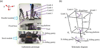
Figure 11 depicts a laboratory prototype and a schematic diagram of the hybrid machine tool.
Laboratory prototype and schematic diagram of the hybrid machine tool.

As can be seen from Fig 11(a), the proposed hybrid machining tool consists of a 2UPR&2RPS parallel module and an X-Y sliding gantry module. Herein, "U", "P", "R", and "S" represent a universal joint, an actuated prismatic joint, a revolute joint, and a spherical joint, respectively. The parallel module is composed of a fixed base, a moving platform, and four limbs. Specially, limb 1 and limb 2 are two symmetrically arranged UPR limbs, while limb 3 and limb 4 are two symmetrically arranged RPS limbs. The moving platform is connected to the fixed base by the four limbs. According to our previous study, the moving platform possesses two rotational and one translational motion capabilities. Therefore, the spindle installed on the moving platform can fulfill 5-axis motions with respect to the workpiece fixed on the X-Y sliding gantries.
As shown in Fig 11(b), A
j
and B
j
(j = 1 ∼ 4) are the geometric center points of the joints connecting to the fixed base and the moving platforms, respectively. The X sliding gantry and the Y sliding gantry are along A
3
A
4 and A
1
A
2, respectively. O and o are the central points of the quadrate of □A
1
A
2
A
3
A
4 and □B
1
B
2
B
3
B
4, while o
 $^{\prime}$
denotes the lower left corner of the upper surface of the workpiece. p is the tool tip. To facilitate kinematic analysis, some coordinate systems are defined. A reference coordinate system O-XYZ is established at O, with X axis pointing to A
4, Y axis pointing to A
1, and Z axis satisfying the right-hand rule. A moving coordinate system o-uvw is established at o, with u axis pointing to B
4, v axis pointing to B
1 and w axis satisfying the right-hand rule. A workpiece coordinate system
 $o'-x'y'z'$
is established at
 $o'$
, with
 $x'$
axis,
 $y'$
axis, and
 $z'$
axis parallel to those of the reference frame of O-XYZ.
4.2. Inverse position solution model
Measured in
 $o'-x'y'z'$
, the position vector of the tool tip and the tool-axis vectors are defined as
 $\boldsymbol{{o}}\boldsymbol{'}\boldsymbol{{P}}=\left[\textrm{x}_{P},y_{P},z_{P}\right]^{\textrm{T}}$
and
 $\boldsymbol{{R}}_{\text{tool}}=\left[x_{\textrm{tool}},y_{\textrm{tool}},z_{\textrm{tool}}\right]^{\textrm{T}}$
, respectively. Measured in O-XYZ, the position vector of
 $o'$
and o are defined as
 $\boldsymbol{{Oo}}\boldsymbol{'}=\left[\textrm{X}_{\textrm{o}'},\textrm{Y}_{o'},\textrm{Z}_{o'}\right]^{\textrm{T}}$
and
 $\boldsymbol{{Oo}}=\left[\textrm{X}_{\textrm{o}},\textrm{Y}_{o},\textrm{Z}_{o}\right]^{\textrm{T}}$
, respectively. The transformation matrix
 $\boldsymbol{{R}}_{\boldsymbol{{o}}}^{\boldsymbol{{O}}}$
of the frame of o-uvw with respect to the reference frame of O-XYZ can be written as:
 \begin{equation} \boldsymbol{{R}}^{O}_{o}=\left[\begin{array}{ccc}\textrm{c}\varphi \textrm{c}\theta& \textrm{c}\varphi \textrm{s}\theta \textrm{s}\psi- \textrm{s}\varphi \textrm{c}\psi & \textrm{c}\varphi \textrm{s}\theta \textrm{c}\psi- \textrm{s}\varphi \textrm{s}\psi \\ \\[-8pt] \textrm{s}\varphi \textrm{c}\theta& \textrm{s}\varphi \textrm{s}\theta \textrm{s}\psi- \textrm{c}\varphi \textrm{c}\psi & \textrm{s}\varphi \textrm{s}\theta \textrm{c}\psi- \textrm{c}\varphi \textrm{s}\psi \\ \\[-8pt]-\textrm{s}\theta &\textrm{s}\psi \textrm{c}\theta& \textrm{c}\theta \textrm{c}\psi \end{array}\right]\end{equation}
where
 $\psi, \theta$
, and
 $\varphi$
are the precession angle, the nutation angle, and the rotation angle; "s" and "c" mean the sine function and the cosine function, respectively.
Measured in O-XYZ, the position vector of the tool tip can be obtained as:
 \begin{equation} \boldsymbol{{OP}}\boldsymbol{=}\boldsymbol{{Oo}}\boldsymbol{+}\boldsymbol{{R}}_{o}^{O}\cdot \left[0,0,L\right]^{\textrm{T}}=\boldsymbol{{Oo}}\boldsymbol{'}\boldsymbol{+}\boldsymbol{{R}}_{o'}^{O}\cdot \boldsymbol{{o}}\boldsymbol{'}\boldsymbol{{P}} \end{equation}
where L is the distance from point p to point o
 $^{\prime}$
; the transformation matrix
 $\boldsymbol{{R}}_{o'}^{O}$
is a third-order unit diagonal matrix.
Taking
 $\psi, \theta$
and
 $Z_{o}$
as the independent motion coordinates of the moving platform, the parasitic motions of the moving platform can be obtained as:
 \begin{equation} \varphi =0, Y_{o}=0, X_{o}=Z_{o}\cdot \tan \theta \end{equation}
Since the movement of o
 $^{\prime}$
is realized by the X sliding gantry and the Y sliding gantry, the position of the two sliding gantries can be obtained by combining Eqs. (27) and (28):
 \begin{equation} \left\{\begin{array}{l} X_{o'}=Z_{o}\cdot \tan \theta +L\cdot \textrm{s}\theta \textrm{c}\psi -x_{P}\\ \\[-9pt]Y_{o'}=-L\cdot s\psi -y_{P}\\ \\[-9pt]Z_{o}=Z_{o'}-z_{P}-L\cdot c\theta c\psi \end{array}\right. \end{equation}
where
 $Z_{o'}$
denotes the distance between plane XOY and plane
 $x'o'y'$
.
Measured in O-XYZ, the tool-axis vector can be expressed as:
 \begin{equation} \boldsymbol{{R}}_{\textrm{tool}}=\boldsymbol{{R}}_{o'}^{O}\cdot \left[x_{\textrm{tool}},y_{\textrm{tool}},z_{\textrm{tool}}\right]^{\textrm{T}}=\boldsymbol{{R}}_{o}^{O}\cdot \left[0,0,1\right]^{\textrm{T}}=\left[\textrm{s}\theta \textrm{c}\psi,-\textrm{s}\psi,\textrm{c}\theta \textrm{c}\psi \right]^{\textrm{T}} \end{equation}
By solving Eq. (30), one may obtain the following equation:
 \begin{equation} \left\{\begin{array}{l} \psi =\arcsin \!\left(\!-y_{\textrm{tool}}\right)\\ \\[-9pt] \theta =\arctan \!\left(x_{\textrm{tool}}/z_{\textrm{tool}}\right) \end{array}\right. \end{equation}
The length of
 $\left| \boldsymbol{{B}}_{j}\boldsymbol{{A}}_{j}\right|$
(
 $q_{j}$
) and its unit direction vector (
 $\boldsymbol{{v}}_{{q_{j}}}$
) can be calculated by Eqs. (32) and (33), respectively:
 \begin{equation} q_{j}=\left| \boldsymbol{{Oo}}+\boldsymbol{{R}}_{o}^{O}\cdot \boldsymbol{{b}}_{j}-\boldsymbol{{a}}_{j}\right|\,(j=1\sim4) \end{equation}
 \begin{equation} \boldsymbol{{v}}_{{q_{j}}}=\left(\boldsymbol{{Oo}}+\boldsymbol{{R}}_{o}^{O}\cdot \boldsymbol{{b}}_{j}-\boldsymbol{{a}}_{j}\right)/q_{j} \ \ (j=1\sim4)\end{equation}
where,
 $\boldsymbol{{a}}_{j}$
is the position vector of
 $\boldsymbol{{O}}\boldsymbol{{A}}_{j}$
(j = 1 ∼ 4) with respect to O-XYZ and
 $\boldsymbol{{b}}_{j}$
is the position vector of
 $\boldsymbol{{o}}\boldsymbol{{B}}_{j}$
(j = 1 ∼ 4) with respect to o-uvw.
4.3. Velocity mapping model
Measured in O-XYZ, letting
 $\boldsymbol{{V}}_{\boldsymbol{{o}}}=\left[V_{oX},V_{oY},V_{oZ}\right]^{\textrm{T}}$
denotes the linear velocity of the geometric center point of the moving platform,
 $\boldsymbol{{W}}_{\boldsymbol{{o}}}=\left[W_{oX},W_{oY},W_{oZ}\right]^{\textrm{T}}$
is the angular velocity of the geometric center point of the moving platform, and
 $\boldsymbol{{V}}_{P}=\left[V_{PX},V_{PY},V_{PZ}\right]^{\textrm{T}}$
represents the linear velocity of tool tip.
The velocity V
j
(j = 1 ∼ 4) of the jth limb along
 $\boldsymbol{{A}}_{\boldsymbol{{j}}}\boldsymbol{{B}}_{\boldsymbol{{j}}}$
(j = 1 ∼ 4) can be expressed as:
 \begin{equation} V_{j}=\left[\boldsymbol{{V}}_{o}+\boldsymbol{{W}}_{o}\times \left(\boldsymbol{{R}}_{o}^{O}\cdot \boldsymbol{{b}}_{j}\right)\right]\cdot \boldsymbol{{v}}_{{q_{\boldsymbol{{j}}}}} \ \ (j=1\sim4)\end{equation}
The relationship between
 $\boldsymbol{{W}}_{\boldsymbol{{o}}}$
and the Euler angular velocity can be expressed as:
 \begin{equation} \boldsymbol{{W}}_{\boldsymbol{{o}}}=\boldsymbol{{J}}_{0}\cdot \left[\begin{array}{c} \dfrac{\textrm{d}\psi }{\textrm{d}t}\\ \\[-9pt]\dfrac{\textrm{d}\theta }{\textrm{d}t}\\ \\[-9pt]\dfrac{\textrm{d}\varphi }{\textrm{d}t} \end{array}\right], \boldsymbol{{J}}_{0}=\left[\begin{array}{c@{\quad}c@{\quad}c} 1 & 0 & -\sin\!\theta \\ \\[-9pt]0 & \cos\!\psi & \sin\!\psi \cos\!\theta \\ \\[-9pt]0 & -\sin\!\psi & \cos\!\psi \cos\!\theta \end{array}\right] \end{equation}
The derivative of
 $X_{o}, Y_{o}, Z_{o}, \psi, \theta$
and
 $\varphi$
with respect to time t can be obtained as:
 \begin{equation} \left[\frac{\textrm{d}X_{o}}{\textrm{d}t},\frac{\textrm{d}Y_{o}}{\textrm{d}t},\frac{\textrm{d}Z_{o}}{\textrm{d}t},\frac{\textrm{d}\psi }{\textrm{d}t},\frac{\textrm{d}\theta }{\textrm{d}t},\frac{\textrm{d}\varphi }{\textrm{d}t}\right]^{\textrm{T}}=T_{P}\cdot \left[\frac{\textrm{d}Z_{o}}{\textrm{d}t},\frac{\textrm{d}\psi }{\textrm{d}t},\frac{\textrm{d}\theta }{\textrm{d}t}\right]^{\textrm{T}} \end{equation}
where
 \begin{equation} \boldsymbol{{T}}_{P}=\left[\begin{array}{c@{\quad}c@{\quad}c} \tan \theta & 0 & \frac{\textrm{d}Z_{o}}{\textrm{d}t}\!\left(1+\left(\tan \theta \right)^{2}\right)\\ \\[-9pt]0 & 0 & 0\\ \\[-9pt]1 & 0 & 0\\ \\[-9pt]0 & 1 & 0\\ \\[-9pt]0 & 0 & 1\\ \\[-9pt]0 & 0 & 0 \end{array}\right] \end{equation}
Combining Eqs. (34) and (36), the velocity mapping relationship between the actuating joints of the parallel module and the center point of the moving platform is obtained as:
 \begin{equation} \left[\begin{array}{l} V_{1}\\ \\[-8pt] V_{2}\\ \\[-8pt] V_{3}\\ \\[-8pt] V_{4} \end{array}\right]=\boldsymbol{{J}}_{a}\cdot \boldsymbol{{T}}_{P}\cdot \left[\begin{array}{c} \dfrac{\textrm{d}Z_{o}}{\textrm{d}t}\\ \\[-7pt] \dfrac{\textrm{d}\psi }{\textrm{d}t}\\ \\[-7pt] \dfrac{\textrm{d}\theta }{\textrm{d}t} \end{array}\right], \boldsymbol{{J}}_{a}=\left[\begin{array}{c@{\quad}c} \boldsymbol{{v}}_{{q_{1}}} & \boldsymbol{{r}}_{1}\times \boldsymbol{{v}}_{{q_{1}}}\cdot \boldsymbol{{J}}_{0}\\ \\[-8pt] \boldsymbol{{v}}_{{q_{2}}} & \boldsymbol{{r}}_{2}\times \boldsymbol{{v}}_{{q_{2}}}\cdot \boldsymbol{{J}}_{0}\\ \\[-8pt] \boldsymbol{{v}}_{{q_{3}}} & \boldsymbol{{r}}_{3}\times \boldsymbol{{v}}_{{q_{3}}}\cdot \boldsymbol{{J}}_{0}\\ \\[-8pt] \boldsymbol{{v}}_{{q_{4}}} & \boldsymbol{{r}}_{4}\times \boldsymbol{{v}}_{q4}\cdot \boldsymbol{{J}}_{0} \end{array}\right] \end{equation}
where
 $\boldsymbol{{r}}_{j}=\boldsymbol{{R}}_{o}^{O}\cdot \boldsymbol{{b}}_{j}$
is the geometric center points of the jth joints connecting to the moving platforms.
It can be seen from Fig. 11(b) that the tool-axis vector can be expressed as:
 \begin{equation} \boldsymbol{{oP}}=\boldsymbol{{R}}_{\boldsymbol{{o}}}^{\boldsymbol{{O}}}\cdot \left[0,0,L\right]^{\textrm{T}} \end{equation}
The velocity of the tool tip can be expressed as:
 \begin{equation} \boldsymbol{{V}}_{P}=\boldsymbol{{V}}_{o}+\boldsymbol{{W}}_{o}\cdot \boldsymbol{{oP}}=\boldsymbol{{J}}_{2}\cdot \left[\begin{array}{l} \boldsymbol{{V}}_{o}\\ \\[-8pt] \boldsymbol{{W}}_{o} \end{array}\right], \boldsymbol{{J}}_{2}=\left[\begin{array}{c@{\quad}c@{\quad}c@{\quad}c@{\quad}c@{\quad}c} 1 & 0 & 0 & 0 & {L}\text{c}\theta \text{c}\psi & L\text{s}\psi \\ \\[-8pt] 0 & 1 & 0 & -{L}\text{c}\theta \text{c}\psi & 0 & {L}\text{s}\theta \text{c}\psi \\ \\[-8pt] 0 & 0 & 1 & -L\text{s}\psi & -{L}\text{s}\theta \text{c}\psi & 0 \end{array}\right] \end{equation}
By substituting Eqs. (34) and (39) into Eq. (40), one may obtain the following equation:
 \begin{equation} \boldsymbol{{V}}_{P}=\boldsymbol{{J}}_{3}\cdot \left[\begin{array}{c} \dfrac{\textrm{d}Z_{o}}{\textrm{d}t}\\ \\[-7pt] \dfrac{\textrm{d}\psi }{\textrm{d}t}\\ \\[-7pt] \dfrac{\textrm{d}\theta }{\textrm{d}t} \end{array}\right], \boldsymbol{{J}}_{3}=\boldsymbol{{J}}_{2}\cdot \left[\begin{array}{c@{\quad}c} \boldsymbol{{E}}_{3\times 3} & \textbf{0}_{3\times 3}\\ \\[-8pt] \textbf{0}_{3\times 3} & \boldsymbol{{J}}_{0} \end{array}\right]\cdot \boldsymbol{{T}}_{P} \end{equation}
where
 $\textbf{0}_{3\times 3}$
is a three-order null matrix.
By combining Eqs. (38) and (41), the mapping relationship between the velocity of the tool tip and the velocity of the actuating joints can be expressed as:
 \begin{equation} \left[\begin{array}{l} V_{1}\\ \\[-8pt] V_{2}\\ \\[-8pt] V_{3}\\ \\[-8pt] V_{4} \end{array}\right]=\boldsymbol{{J}}_{1}\cdot \left(\boldsymbol{{J}}_{3}\right)^{-1}\cdot \boldsymbol{{V}}_{P} \end{equation}
Since the X sliding gantry and the Y sliding gantry are connected in series, the velocity of the serial module is the velocity of the actuating joints. So the velocity of the actuating joints can be obtained as:
 \begin{equation} \left\{\begin{array}{l} V_{5}=V_{Cx}=\dfrac{X_{oe}-X_{os}}{T}\\ \\[-7pt]V_{6}=V_{Cy}=\dfrac{Y_{oe}-Y_{os}}{T}\\ \\[-7pt]V_{Cz}=0 \end{array}\right. \end{equation}
where
 $V_{\boldsymbol{{Cx}}}, V_{\boldsymbol{{Cy}}}$
, and
 $V_{\boldsymbol{{Cz}}}$
are the velocity components of the serial module measured in
 $o'-x'y'z'$
, respectively.
 $X_{os}, Y_{os}, X_{oe}$
, and
 $Y_{oe}$
are the displacement of the X sliding gantry and the Y sliding gantry corresponding to adjacent tool tip measured in
 $o'-x'y'z'$
.
4.4. Velocity allocation
Since the joint space and the operation space are nonlinear, the velocity of joint space must be allocated in order to determine the velocities of parallel mechanism and serial mechanism. Then combined with the velocity mapping model of hybrid machine tool, the velocity corresponding to the actuating joints is obtained.
When the velocity curve of tool tip is known, the interpolated tool tip and the interpolation period can be obtained by trajectory control strategy as proposed in Section 3. After trajectory control, the position vectors of adjacent interpolation tool tip are expressed as
 $\boldsymbol{{P}}_{\textrm{s}}=\left[x_{Ps},y_{Ps},z_{Ps}\right]^{\textrm{T}}$
and
 $\boldsymbol{{P}}_{\boldsymbol{{e}}}=\left[x_{Pe},y_{Pe},z_{Pe}\right]^{\textrm{T}}$
, respectively. So the tangential velocity of tool tip along the toolpath can be expressed as:
 \begin{equation} \left\{\begin{array}{l} V_{Fx}=\dfrac{x_{Pe}-x_{Ps}}{T}\\ \\[-7pt]V_{Fy}=\dfrac{y_{Pe}-y_{Ps}}{T}\\ \\[-7pt]V_{Fz}=\dfrac{z_{Pe}-z_{Ps}}{T} \end{array}\right. \end{equation}
where
 $\boldsymbol{{V}}_{\boldsymbol{{F}}}=\left[V_{Fx},V_{Fy},V_{Fz}\right]^{\textrm{T}}$
is the tangential velocity of the tool tip along the toolpath measured in
 $o'-x'y'z'$
.
Because the tangential velocity of tool tip along the toolpath is the synthetic velocity of parallel mechanism and serial mechanism, the velocity of parallel mechanism with respect to O-XYZ can be expressed as:
 \begin{equation} \left\{\begin{array}{l} V_{PX}=V_{Fx}-V_{Cx}\\ \\[-7pt]V_{PY}=V_{Fy}-V_{Cy}\\ \\[-7pt]V_{PZ}=V_{Fz}-V_{Cz} \end{array}\right. \end{equation}
By substituting Eq. (45) into Eq. (42), the velocity of each actuating joint can be obtained.
5. Experimental tests
5.1. Developments of the proposed method
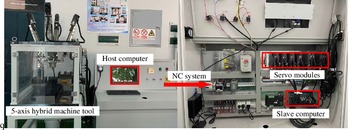
To perform the machining tests, an open-architecture NC system is constructed as shown in Fig. 12.
NC system of the developed 5-axis hybrid machine tool.

As shown in Fig. 12, the NC system is composed of a host computer (personal computer), a slave computer, six servo modules, and other electrical components. The slave computer is SMC606 multi-axis motion controller. The model of six servo modules is HG-KR43BJ, whose pulse frequencies are all set as 10 kHz. By considering the lead of ball screw (5 mm), the resolution of each prismatic joint can be calculated as 5 × 10⁻⁴mm.
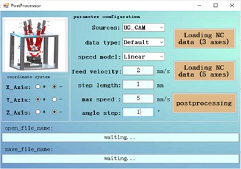
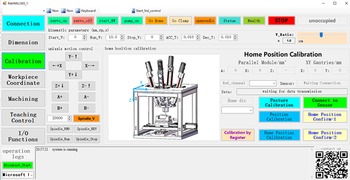
Meanwhile, based on the proposed smooth toolpath interpolation method, a post-processor and a Human–Machine Interface (HMI) system are developed and demonstrated in Figs. 13 and 14.
The Graphical User Interface of post-processor.

The Graphical User Interface of HMI system

As shown in Fig. 13, the post-processor is to generate a smooth toolpath and export a set of optimized NC codes by importing the original NC codes, which integrates the functions of velocity control and trajectory control. Herein, the velocity control is applied to calculate a smooth velocity curve of tool tip for avoiding sudden changes in acceleration and reducing velocity fluctuation. The trajectory control is applied to generate a smooth toolpath and calculate the corresponding interpolated tool-axis vectors and the corresponding interpolated tool tips.
As shown in Fig. 14, the HMI system is used to process user instructions and realize the motion control of a hybrid machine tool. It integrates the functions of kinematics transformation. To be specific, the inverse position solution model is to transform the tool tips and the tool-axis vectors into the displacement of actuated joints. The velocity mapping model is to transform the velocity of tool tip into the velocity of actuated joints.
5.2. Machining test
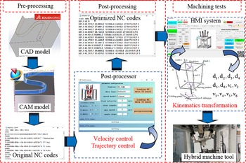
Figure 15 depicts an overview of 5-axis machining operation by using the proposed toolpath generation method.
Overview of 5-axis machining operation.

As can be seen from Fig. 15, the proposed methodology includes three stages, that is, pre-processing, post-processing, and machining tests.
(1) During the pre-processing stage, a 3D CAD model of the workpiece is developed by using SolidWorks software. This CAD model is then transformed into a CAM model to generate the original NC codes, which include the tool tips and the tool-axis vectors data.
(2) During the post-processing stage, the NC codes are imported into a self-developed post-processor to generate a smoother toolpath and export a set of optimized NC codes.
(3) During the machining tests stage, the optimized NC codes are input into the HMI system of the hybrid machine tool. Based on the inverse position solution and the velocity mapping model, the imported NC codes are transformed into the displacements and the velocities of actuated prismatic joints. Driven by the six servo motors simultaneously, the proposed hybrid machine tool can implement machining tasks.
In order to verify the effectiveness of the proposed smooth toolpath interpolation method, we carried out two sets of machining tests on S-shape workpieces [Reference Wang, Wu and Wang19, Reference Geng, Yu, Zheng, Zhang and Wang38] to verify the effectiveness of the proposed smooth toolpath interpolation method. For clarity, the experimental conditions between the two sets of machining tests are given and compared in Table II. Where the PVT (P: position; V: velocity; T: time) is a interpolation motion pattern based on Hermite cubic spline curve. By using this motion pattern, the users can control the position and the velocity of each actuated joint at any time.
As can be seen from Table II, the two sets of machining tests are set to the same experimental conditions except for the NC codes. In the first machining test, the NC codes are obtained directly from the CAM software. In the second machining test, the NC codes are optimized by using the proposed smooth toolpath interpolation method.
The velocity feedback values of the tool tip are recorded in real time to reflect the velocity fluctuation in the two set of machining tests. The results are depicted in Fig. 16.
The velocity fluctuation in two set of machining test.

As can be seen from Fig. 16(a), the velocity vary in the intervals of [0.24, 29.84] mm/s in the first machining test. The average value of velocity fluctuation can be calculated by Eq. (46) as 0.59 mm/s. As can be seen from Fig. 16(b), the velocity vary in the range of [2.07, 14.26] mm/s in the second machining test. The average value of velocity fluctuation can be obtained as 0.4 mm/s. It is obvious that the average value of velocity fluctuation is decreased by 32.2% after using the proposed velocity control strategy. This indicates that the proposed velocity control strategy helps to reduce the velocity fluctuation:
 \begin{equation} \overline{v}_{f}=\frac{\sum\limits_{i=0}^{N_{P}}\left(v_{i}-F\right)}{N_{P}} \end{equation}
where
 $\overline{v}_{f}$
is the average value of velocity fluctuation,
 $v_{i}$
is the velocity of ith acquisition point, and
 $N_{P}$
is the total number of acquisition points.
Figure 17 depicts the two machined S-shape workpiece.
Two set of S-shape workpiece after machining.

As shown in Fig. 17, the total machining time of the first machining test is about 648s, and the total machining time of the second machining test is about 689s. Obviously, the time increase after using the smooth toolpath interpolation method is only 6.33%, which has little impact on the overall machining efficiency.
As can be observed from Fig. 17(a), there are some tool marks on the surface of the first machining test. As can be observed from Fig. 17(b), most of tool marks are disappeared from the surface of the second machining test. This indicates that the proposed smooth toolpath interpolation method can effectively improve the surface quality of machining workpiece without reducing machining efficiency.
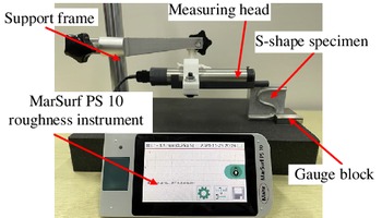
As shown in Fig. 18, to further compare the surface quality of the two set of S-shape workpiece, geometric errors of surface contour are tested with MarSurf PS 10 roughness instrument. The position of the S-shape workpiece is positioned by the gauge block to ensure that the starting point and the ending point of the evaluation length are in the same position.
S-shape workpiece test platform of geometric error of surface contour.

Figure 19 depicts the results of geometric error of surface contour.
Geometric error in two set of machining test.

As shown in Fig. 19, the maximum height Rz of the contour of the first machining test is 5.612 µm, which of the second machining test is 4.398 µm. It is obvious that Rz is decreased by 21.6%. The calculated average deviation Ra of the contour of the first machining test is 1.016 µm, which of the second machining test is 0.660 µm. It shows that Ra is decreased by 35.0%. This further indicates that the proposed smooth toolpath interpolation method can effectively improve the surface quality of machining workpiece.
From the above comparison, it can be concluded that the first machining test is smoother than the second machining test. At the same time, the velocity fluctuation can be significantly reduced by using the proposed velocity control strategy.
6. Conclusions
Based on the investigations conducted in this paper, the following conclusions can be drawn.
(1) B-spline curve is adopted to formulate a tool tip curve, based on which the curvature of tool tip curve is calculated to determine the constraint of the chord error and the centripetal acceleration. Under the constraints of the chord error, the centripetal acceleration and the contouring error, the velocity at the constrained velocity points will be controlled to less than the rated velocity value. By combining the five-phase S-shape curve and the trigonometric function curve, one may avoid sudden changes in acceleration and reducing the velocity fluctuation of the tool tip.
(2) A new trajectory control strategy is proposed, which includes the techniques of interpolation algorithm and parameter synchronization. To be specific, a B-spline curve-based interpolation algorithm is proposed to obtain the interpolated tool tip. The parameter synchronization is used to ensure the synchronization of the interpolated tool-axis vectors and the interpolated tool tip. Thanks to the trajectory control used in the tool tip, the trajectory smoothness can be effectively improved.
(3) A kinematics transformation is established for the 5-axis hybrid machine tool to transform the NC codes into the displacements and velocities of actuated joints.
(4) The effectiveness of the proposed methodology is verified by a set of machining tests on S-shape workpiece. The experimental results indicate that the average value of velocity fluctuation is decreased by 32.2% after using the proposed velocity control strategy. And the values of Rz and Ra are decreased by 21.6% and 35.0% after using trajectory control. Therefore, the proposed smooth toolpath interpolation method can improve the surface quality of machining workpiece and reduce the velocity fluctuation of the tool tip.
(5) Our future work will focus on the following issues. First, vibration error caused by external force will be considered in the trajectory control. Second, dynamics of hybrid machine tool will be taken into account. Thirdly, the scheduled velocity profile will be time-optimized to improve the machining efficiency. They will be investigated in-depth in our future work.
Author Contributions
All authors conceived and designed the study. Zhen He, Hanliang Fang, and Yufei Bao implemented the research. Zhen He and Hanliang Fang carried out the experiment and conducted analysis. Zhen He wrote the manuscript. Fufu Yang and Jun Zhang reviewed and edited the manuscript.
Financial Support
This work is jointly supported by the Open Fund of the State Key Laboratory for Mechanical Transmissions, Chongqing University (Grant No. SKLMT-ZDKFKT-202003), the Industry-Academy Cooperation Project of Fujian Province (Grant No. 2019H6006), and the Natural Science Foundation for Distinguished Young Scholar of Fujian Province (Grant No. 2020J06010). The corresponding author is also thankful to the sponsor of National Natural Science Foundation of China (Grant No. 51875105).
Conflicts of Interest
None.
Ethical Considerations
None.