I. INTRODUCTION
The tribological aspect in a hot forming process has a crucial role to predict. Indeed, wear is usually a result of one hand, the relative slide between the material and the tool and the role of the third body in another hand. Many researchers have been concerned with this phenomenon, indicating that these systems are complex in soft contact. In fact, the surfaces evolve continuously over time. Reference Dohda, Boher, Rezai-Aria and Mahayotsanun1–Reference Xiao, Yao, Zhou, Zhang, Gong, Zhao, Zuo, Deng and Jin6 The light has also been shed on the effects of the third body on the tribological properties and wear of materials. Actually, several studies have confirmed that the presence of the third body, their formation, and their evolution greatly affects the tribological properties of materials friction. Reference Godet7–Reference Östrelle and Urban14
In hot forming process, the final product is in constant renewal surface. Therefore, the formation of the third body gives a special importance to the kinetics of the tribo-chemical reactions and mass transfer. Indeed, the understanding of tribological phenomena that take place at the high temperature contact is particularly complex because of the different parameters that come into play in the tribosystem (thermal, mechanical …). Reference Zhu, Zhu, Tieu and Kong15
Moreover, Stott and Wood Reference Stott and Wood16 have shown that in the high temperature, wear does not only depend on the friction between the two antagonist materials, but also on the impact of oxide layers. Vergne et al. Reference Vergne, Boher, Levaillant and Gras17 indicated that these oxide layers reach a critical thickness and then deteriorated and produced cracks in the surface of the tool and the product. The same authors Reference Stott and Wood16 have demonstrated that the wear observed on the surface of the first body depends on the nature and mechanical properties of the oxides present in the contact. Matuszak Reference Matuszak18 affirmed that the behavior of friction materials depends on several parameters such as the contact pressure, sliding speed, and the type of antagonist materials, surface roughness, and type of lubricants. In tribology, oxides generally having an ambiguous role can be both abrasive and therefore source of damage or lubricants and consequently protective. Reference Fontalvo and Mitterer19–Reference Szakaly and Lenard22 These tribological properties are correlated to their microstructure and mechanical properties. Thus, the friction coefficient generated between the layers of oxides is generally dependent on the nature, the thickness, and the adhesion or hardness of these oxides.
In oxidative mild wear, the tribo-oxide layer plays a decisive role, as reported in most research works on oxidative wear. Reference Lepesant, Boher, Berthier and Rezai-Aria23,Reference Hong and Winner24 The oxidative mild wear has been considered to be related only to tribo-oxides. The tribo-oxide layer prevents metal–metal contact and thus reduces wear. The substrate and its microstructure were not mentioned to have influence on wear behavior. However, the generation of wear debris and material transfer between the two antagonist materials may also be produced during the friction, which, actually, depends on the ability of these wear particles to be free or compacted. Stott et al. Reference Stott and Wood16,Reference Stott, Gascott and Wood25 have shown that the ability of particles oxides to be loose or compact to the contact surface is generally associated with the microstructure and mechanical properties of the oxides, on the one hand, and the friction condition on the other. Jiang et al. Reference Jiang, Stott and Stack26 have shown that the development of oxides can reduce the coefficient of friction and wear particularly at high temperatures. During the friction, the particles of the third body are in constant movement and are subjected to different shear rates.
The ultimate target of this contribution is to model the wear mechanisms in an open sliding contact at high temperature by the friction of X40CrMoV5 hard high-alloyed steel against soft Fe360B steel. For this purpose, an approach based on the contact analysis was adopted. Thus, we must recognize the responses of the first bodies and those of the third body.
This research work was carried out with pin-on-disc tribometer. The function of wear fragment particles during sliding in the wear procedure and the combination of the involvement of wear fragments particles in wear procedure were discussed.
II. EXPERIMENTAL DETAILS
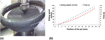
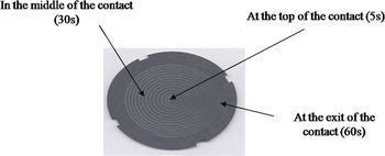
The tests were conducted using a high temperature pin-on-disc tribometer with an open sliding contact on an all-the-time refreshed disc surface. Reference Baccouch, Mnif, Elleuch and Richard27 The machine is based on an open contact at high temperature. The pin whose removal was mechanically managed by thrusts was conformed to a translation movement (v) by a direct unit. The pin began from the center of the disc and cross to the edge. The disc moved in rotary direction (ɷ) managed by an electric motor. The normal load (F) and the rotary sliding speed (ɷ) were retained invariable. The test lasts 60 s on each disc. The same experimental parameters were used for all the specimens: High temperature of 600 °C, 70 N for the normal charge; 50 rev/min for the rotation speed; 1–128 mm/s for the sliding speed (Fig. 1); 1500 mm for the sliding distance. The obtained trajectory was spiral (Fig. 2). After every experiment, to distinguish the damage procedure, wear surfaces were investigated and examined by a scanning electronic microscope followed by an energy-dispersive ray. A Philips XL30 ESEM-FEG (FEI Company, Hillsboro, Oregon) environmental sample was made into practice for these investigations.
(a) Tribometer in an open contact at high temperature. (b) Evolution of the sliding velocity and time based on the position of the pin in time for the disc speed (ɷ = 50 rev/min). Reference Baccouch, Mnif, Elleuch and Richard27

Typical microscopic observation of the friction disc detailing the study areas.

The structure and composition of worn surfaces were analyzed using an X-ray diffractometer (XRD). It has a curved detector Inel CPS 120 (Inel, Artenay, France) coupled to a phase search software Diffrac Plus 5.1 (Bruker AXS, Bruker Corporation, Karlsruhe, Germany) using the JCPDS file, with a multichannel analyzer 4096 channels to 120°/20, or an accuracy of 3°/100. This conventional assembly is used to identify the phases in thicknesses of a few tens of microns.
Figure 2 shows a typical microscopic observation of the friction surface detailing the different study areas. The objective of these tests is to elucidate the phenomenon of the movement of the third body namely oxides and metal oxides present at the surface.
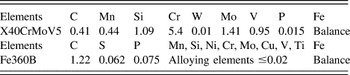
The X40CrMoV5 high alloy steel was used as a pin in this study. The pin steel was studied in quenched and tempered conditions. The Fe360B steel disc was representing drawing products. The diameter of the disc was 45 mm and its thickness was 2 mm. The heat approaches were accomplished to realize a primary hardness of 47 HRC with tempered martensitic microstructure. The contact surface area was 1.5 mm, and the arithmetic average roughness (R a) values of the disc and the pin were 1.53 and 1.72 µm, respectively.
Table I shows the chemical elementary composition of X X40CrMoV5 and Fe360B ultrahigh carbon steel (in weight percent, wt%).
Chemical elementary composition of X40CrMoV5 high-alloyed steel and Fe360B ultra high carbon steel (in weight percent, wt%).

III. RESULTS AND DISCUSSION
During friction, the particles of the third body are continually in movement and subjected to different shear rates. This material flowing inside and outside the contact is defined by the term of tribological system, a concept suggested by Y. Berthier and Descartes. Reference Godet7
This part’s aim is to collect various results to better understand the phenomena observed during the friction in an open contact of our studied couple X40CrMoV5/Fe360B.
A. Reaction of third body at the surface Fe360B
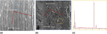
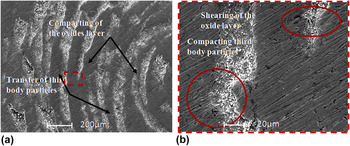
Figure 3 represents the surface of the disc Fe360B after a test of friction (t = 60 s, T = 600 °C, F = 70 N, ɷ = 50 rev/min). We observe two types of morphology of the third body particles. The first type is a third is composed of oxide layers which shear with respect to each other. This layer flows under the mechanical action of friction in a ductile manner. The second type is a third body which is powdered and composed of small spherical particles. These particles are, therefore, meant into contact by friction and sometimes ejected for wear [Fig. 3(b)]. The EDS analysis of these particles [Fig. 3(c)] shows that all these particles are derived from the oxidation of the disc Fe360B.
Third body covered of the Fe360B track after a tribological test (t = 60 s, T = 600 °C, F = 70 N, ɷ = 50 rev/min). (a) MEB observation of the surface scraped, (b) details of the area, and (c) EDS analysis.

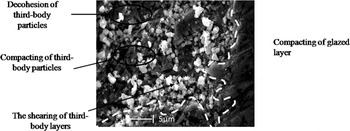
The oxidation of the third body during the friction causes the decohesion of these particles. The oxide layer comprised in the track surface undergoes shear (Fig. 4).
Morphology of the third body of the track Fe360B after a tribological test (t = 60 s, T = 600 °C, F = 70 N, ɷ = 50 rev/min).

Hence, we notice that the compacting and the fragmentation of the third body particles are done instantly.
Actually, the particles can get detached from the first bodies due to the degradation. Hence, it is an internal source of oxidation that leads to the development of the third natural body in contact. These particles of third body can remain trapped in contact or can be evacuated out of contact.
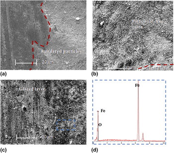
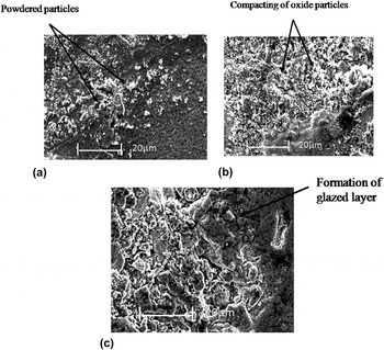
Figure 5 shows the temporal progress of the track surface Fe360B at (T = 600 °C, F = 70 N, ɷ = 50 tr/min). In fact, at the beginning of the test, the contact is X40CrMoV5/oxide of Fe360B [Fig. 5(a)]. The small oxide particles coming from the track can then be formed by the relative motion of surfaces. Some particles from contact are affected by the temperature and many constraints (burden, speed of sliding); these particles can be then oxidized [Fig. 5(b)]. These fragmented and oxidized particles can be joined to surfaces and can be gathered in localized areas such as cavities [Fig. 5(b)]. Subsequently, the particles of the third body shaped and gathered together are compressed and then compacted. When surrounding areas are exploited, they become themselves bearing areas. During this process, the particles are sintered and they shape solid layers protective against wear: iced layers [Fig. 5(c)]. The EDS analyses show that this shaped layer is composed of iron oxides derived from the track [Fig. 5(d)].
Temporal progress of third body covering the track Fe360B after a trobological test (T = 600 °C, F = 70 N, ɷ = 50 rev/min). (a) 5 s, V g = 14 mm/s, (b) 30 s, V g = 28 mm/s, (c) 60 s, V g = 118 mm/s, and (d) EDS analysis.

From these results, the wear is not only considered related to the degradation of the first bodies but also its represented by the output of particles out of the contact.
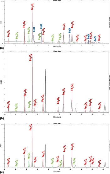
Figure 6 represents the X-ray patterns of the various zones of study. Before every try of friction, the record is preoxidized and a layer of iron oxide is formed on its surface. This layer is called scale which consists of wüstite, magnetite, and hematite. The latter is the layer in extreme surface. Thus, it is her who takes care of the friction.
XRD pattern of the temporal progress of the third body covering the disc Fe360B after a tribological test (T = 600 °C, F = 70 N, ɷ = 50 rev/min). (a) 5 s, V g = 14 mm/s; (b) 30 s, V g = 28 mm/s; (c) 60 s, V g = 118 mm/s.

We note the presence of the layers of oxides to know the hematite, the wüstite, and the magnetite at the beginning of the contact [Fig. 6(a)]. Afterward, the extreme layer of wüstite disappears during the friction (in the middle and at the exit of the contact) [Figs. 6(b) and 6(c)].
B. Response of third body to the surface of the pin X40CrMoV5
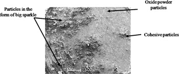
The analyses of the surface of the pin X40CRMoV5 after a friction test (t = 60 s, T = 600 °C, F = 70 N, ɷ = 50 tr/min) show that three phenomena interfere during our tests: the oxidation, the transfer, and the friction since the beginning of test. So, three morphologies of detached particles come out of: particles in the form of big sparkle, cohesive particles, and powder particles of oxides. These three morphologies of particles correspond to certain compositions and many rheologies. In addition, two separate sources flows associated with these particles are induced. These particles are detached from the surface only by oxidation (Fig. 7). These particles correspond to the activation of flow. (These particles are derived from the detachment caused by the friction of the material and the oxide layer of the track Fe360B).
Third body covering the pin X40CrMoV5 after a tribological test (t = 60 s, T = 600 °C, F = 70 N, ɷ = 50 rev/min).

This third body comes from the detachment of oxide layer provoked by the friction. It is composed of particles of iron oxide, and they are located on the edge of the pin surface.
From the morphological observations of the surface of the pawn X40CrMoV5, we notice the presence of the third body which represents a material transfer of the track on the pin [Fig. 8(a)]. These fragmented and oxidized particles adhere to the surfaces and gather together in the localized areas such as cavities caused by machining [Fig. 8(b)].
Third body covering the pin X40CrMoV5 after a tribological (t = 5 s, T = 600 °C, F = 70 N, ɷ = 50 rev/min). (a) MEB Observation, (b) detail of the area.

Figure 9 explains the temporal development of the third body covering the surface of the pawn X40CrMoV5. The speed of sliding evolves over time.
-
(i) At a certain moment t ≤ 5 s, contact X40CrMoV5/oxide of Fe360B, small oxide particles in the surface of the pawn are noticed [Fig. 9(a)]. These particles establish a transfer of the oxide layer raised from the track.
-
(ii) At 5 s ≤ t ≤ 30 s, these particles can then get oxidized under the effect of certain applied charges [Fig. 9(b)]. After that, these fragmented and oxidized particles can be joint to the surfaces and gathered together [Fig. 9(b)].
-
(iii) At 30 s ≤ t ≤ 60 s, the particles are sintered and they shape solid layers protective against wear: iced layers [Fig. 9(c)]. The increase of the sliding speed during the test then leads to the creation of the iced layer in the surface of the pin [Fig. 9(d)]. Actually, since the surface of the track is continuously renewed during the test under the effect of friction and the sliding speed evolves throughout time. This proves the existence of a flow of specific third body related to the application of friction, which is the internal flow of friction.
Temporal development of third body covering the pin X40CrMoV5 after a tribological test (T = 600 °C, F = 70 N, ɷ = 50 rev/min). (a) 5 s, V g = 14 mm/s, (b) 30 s, V g = 28 mms/s, and (c) 60 s, V g = 118 mm/s.

C. Synthesis
In the study of wear mechanisms, the process followed is that of the study of the friction of materials in contact X40CrMoV5. So, the study is accomplished through the friction behavior of pin/disc in an open contact. At this time, the interpretation of results is based on the study of friction factor and friction disc.
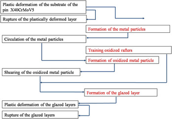
Figure 10 illustrates the schematic representation of the mechanism of wear of the pin. Indeed at the beginning of the test, the contact is X40CrMoV5 X40CrMoV5/Oxyde of Fe360B. In fact, it is clearly seen that the oxide particles have small sizes on the surface of the pin. These particles constitute a transfer of the layer of oxide coming from the disc. The deformation blows up undergone by the pin led to the formation of the metallic particles. These particles can then oxidize under the influence of the various applied loads. Then, these split-up and oxidized particles can adhere to the surfaces and gather together. Then, particles are sintered and form protective solid layers toward the wear: glazed layers. Indeed, as the disc surface is continually renewed during the test, there is the presence of oxidized low chemistry plates and having a more cohesive and adhesive rheology.
Schematic representation of the wear mechanism of the pin X40CrMoV5.

IV. CONCLUSIONS
The purpose of this study is to identify the wear mechanism of the pin. It is initially composed of a lamination of the surface and then an accumulation of the plastic deformation to finally appear at the rupture of the plastic layer and to the release of wear debris. The first step is the formation of metal particles that are then oxidized during their movement within the contact. The second step is the formation of an ice layer on the surface of the pins. Next, this glazed layer can rupture, and oxide particles enter, then turn into the circulation of the third body in the ignition. At the trace of wear on Fe360B disc, two main phenomena were observed, which are the wear of the surface oxide and localized formation of glazed layers.
ACKNOWLEDGMENTS
The authors acknowledge SOPAL Society (Tunisia), especially its head manager for his precious help and contribution to this research.