1. Introduction
The spatial 3-degree-of-freedom (DOF) 2R1T parallel mechanism (PM), chiefly characterized by compact structure, high stiffness, and strong bearing capacity as well as hybrid output of translation and rotation, has a wide range of applications in cutting, multiforce loading, friction stir wielding, and polishing for large components [Reference Ye and Li1–Reference Gao and Zhang3]. Therefore, the in-depth study for the 2R1T PM has profound academic value and engineering significance.
In recent decades, scholars have carried out a series of studies on 2R1T PMs and yielded substantial results. For instance, a 5-DOF hybrid mechanism (named as Tricept robot) was invented in 1988, whose spindle head module is a 2R1T type 4-limb fully symmetrical 3UPS-UP PM (P, prismatic joint; U, universal joint; S, spherical joint) [Reference Li, Chai and Chen4]. For 3UPS-UP manipulator, since the unconstrained UPS active limb does not impose any constraints on the end-effector, the DOF is determined by the suitable constrained UP passive limb. However, the coupling degree of 3UPS-UP PM is 2, which means the forward displacement solution is complex. Making the passive UP limb active, Huang et al. [Reference Huang, Li, Zhao, Mei, Chetwynd and Hu5] put forward 2UPS-UP PM, i.e., the spindle head module of TriVariant robot, and the coupling degree of this PM is 1, which can reduce the complexity of the forward kinematics. On the basis of Tricept, Neumann invented Exechon robot by designing the spindle head as a planar symmetrical 2UPR-SPR PM [Reference Liu, Xie and Wang6]. The Z3 spindle head, proposed by Walt, is a 2R1T type centrosymmetric 3-RPS mechanism [Reference Xie, Liu and Li7]. The aforementioned Tricept, TriVariant, Exechon, and Z3 spindle have been successfully put into commercial application. 2R1T PMs with zero-coupling degree have the advantage of analytical forward and inverse displacement solutions, thus simplifying efficiently pose calibration, trajectory planning, and real-time control [Reference Yang, Liu, Shen, Hang, Luo and Jin8]. Adopting the position and orientation characteristic (POC) set theory, Shen et al. [Reference Shen, Wang and Li9] designed a 2R1T type PM with zero-coupling degree. In Ref. [Reference Liu, Xu, Shen, Shan and Yang10], multiple PMs with zero-coupling degree are generated by using the structural decoupling principle. However, the achievements in Refs. [Reference Shen, Wang and Li9, Reference Liu, Xu, Shen, Shan and Yang10] did not involve motion/force transmissibility analysis and dimensional synthesis.
Dimensional synthesis is the basis and premise for engineering application of PMs, which can be defined as a mechanism parameter optimization design problem with the desired objective of performance indices being as good as possible. Therefore, constructing reasonable performance evaluation indices is an important aspect for dimensional synthesis of PMs. The motion/force transmission performance indices, proposed by Liu et al. [Reference Wang, Wu and Liu11–Reference Xie, Liu and Wang13], have the advantages of dimensionless and independent coordinate system, which are widely used to evaluate the kinematic performance of PMs with hybrid DOFs of translation and rotation. Wang et al. [Reference Wang, Wu, Chen and Li14] used motion/force transmissibility indices to evaluate the performance of three 1T2R PMs and select optimal configuration. As an aspect of dimensional synthesis, Che et al. [Reference Che, Yi and He15] applied motion/force transmissibility indices to evaluate the performance of 2PUS-UP PM, thus realizing the optimization design with maximum good transmission orientation capacity (GTOC). Taking workspace and global transmission index (GTI) as objective functions, Wang et al. [Reference Wang, Chen and Wu16] obtained optimal dimensional parameters of 2UPR-SPR PM by spatial model method. Ye et al. [Reference Ye, Xie and Li17] carried out dimensional synthesis for a remote center motion 2R(Pa)RR-R(Pa)RC PM to improve the global performance. With the aid of performance atlas, Wang et al. [Reference Wang, Xu and Guan18] addressed the multiobjective optimization for 2R1T type 3-PUU PM and obtained good results to meet the corresponding engineering requirements.
The main contributions of this paper are to design a novel asymmetric 2R1T PM with zero degree and to construct its constrained optimization model of dimensional parameters on maximizing GTOC, which is then solved by differential evolution (DE) algorithm together with constraints handling technique. The rest of this paper is organized as follows. In Section 2, the configuration design and analysis of UPS-RPU-PU PM are carried out. The analytical mathematical model of forward and inverse displacement solutions are deduced in Section 3, whose correctness is verified through numerical example and motion simulation. Utilizing screw theory as mathematical tool, Section 4 constructs the analytical formulae for local transmission index (LTI) of UPS-RPU-PU mechanism and identifies the definitions and calculation methods of the good transmission orientation workspace (GTOW), GOTC, and GTI. In Section 5, the constrained optimization model is constructed to formulate dimensional parameters on the maximizing GTOC, which is then solved by DE algorithm. Section 6 gives an application prospect of the optimized mechanism. Finally, this paper is concluded in Section 7.
2. Analysis of mechanism configuration
2.1. Topological coupling-reducing design for 2R1T PM
For 1T2R or 2R1T type PMs, a simple and direct design method is to adopt three active unconstrained limbs and one 2R1T type passive limbs to assemble whole PMs. With this method, partial typical configurations for 2R1T PMs are included in Table I. In the table, P represents actuating joints, and the three active limbs are arranged symmetrically. The coupling-degree
 $\kappa$
of 2R1T PMs in Tables I is 2 by using the calculation method in Ref. [Reference Yang, Liu, Shen, Hang, Luo and Jin8], which means kinematics modeling of this family of PMs is complex. With the aid of method in Ref. [Reference Shen, Wang and Li9], the
 $\kappa$
of aforementioned PMs can be reduced to 1 by changing passive chains into the active (seen in Fig. 1).
Partial 1T2R PMs with one passive suitable constrained branch.

Partial 2R1T PMs with coupling degree equal to 1.

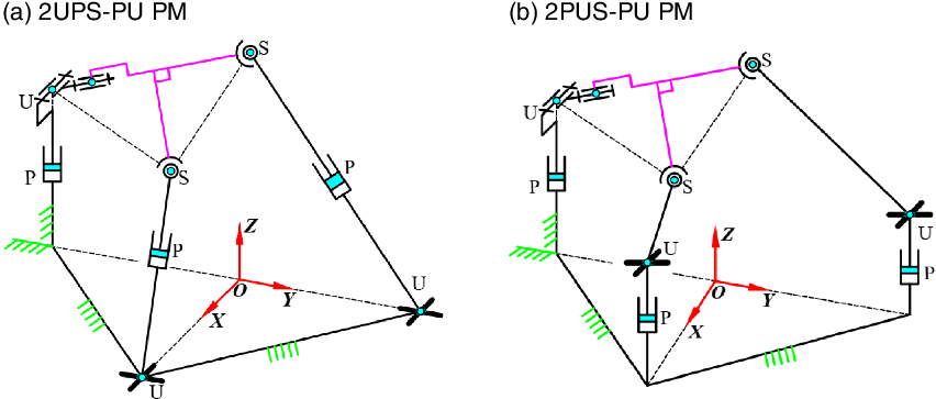
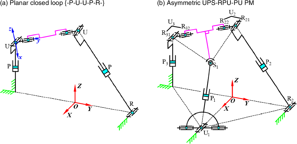
For PMs with the same limb structure, the kinematic characteristics will change due to the different assembly methods of the kinematic joints connected to the base or moving platform. 2UPS-PU PM being taken as an example, the spatial closed loop {-P-U-S-P-U-} will be degenerated into a planar loop by coaxially assembling S and U joints connected with moving platform. In the planar closed loop, the kinematic mode of S and U joints can be considered as U and R joints shown in Fig. 2(a), thus obtaining a novel asymmetric UPS-RPU-PU PM shown in Fig. 2(b).
The evolution process of UPS-RPU-PU PM.

From Fig. 2(b), the asymmetric UPS-RPU-PU PM can be decomposed into two single open chains (SOCs), i.e., SOC1 {P3-R31-R21-P2-R2} and SOC2 {U1-P1-S1-R32(R22)}. According to the method in Ref. [Reference Yang, Liu, Shen, Hang, Luo and Jin8], the constraint degree
 ${\unicode[Times]{x1D6E5}}_i$
(i = 1, 2) of two SOCs can be written as
 \begin{equation} \left\{\begin{array}{l} {\unicode[Times]{x1D6E5}} _{1}=\sum _{i=1}^{5}f_{1i}-I_{1}-\varsigma _{\textrm{L}1}=5-2-3=0,\\[5pt] {\unicode[Times]{x1D6E5}} _{2}=\sum _{i=1}^{4}f_{2i}-I_{2}-\varsigma _{\textrm{L}2}=7-1-6=0, \end{array}\right. \end{equation}
where f
ij
is the DOF of jth kinematic pair in SOC
i
, I
i
is the number of actuated joints in the i-th SOC.
 $\varsigma _{\textrm{L}i}$
is the number of independent displacement equations of the SOC
i
, which can be obtained through the method in Ref. [Reference Liu, Xu, Shen, Shan and Yang10].
The couple degree
 $\kappa$
of UPS-RPU-PU PM can be obtained as
 \begin{equation} \kappa =\frac{1}{2}\min \!\left\{\sum _{j=1}^{2}\left| {\unicode[Times]{x1D6E5}} _{j}\right| \right\}=\frac{1}{2}\times 0=0. \end{equation}
Notice that the couple degree
 $\kappa$
is equal to 1 when the SOC1 is composed of limbs 1 and 3 and SOC2 is limb 2 (i.e., SOC1{P3-R31-S1-P1-U1} and SOC2{R2-P2-R21-R22(R32)}). From Eq. (2), the couple degree is reduced to 0 when UPS-RPU-PU is decomposed with limbs 2 and 3 being SOC1 and limb1 being SOC2, which indicates that this asymmetric UPS-RPU-PU PM has significant advantages of decoupling characteristic.
2.2. Architecture description
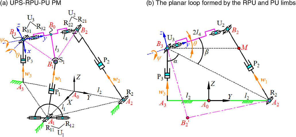
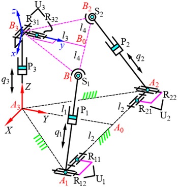
The kinematic sketch of UPS-RPU-PU PM is presented in Fig. 3(a). The fixed base A 1 A 2 A 3 is an isosceles triangle, while the moving platform B 1 B 2 B 3 is designed as an equilateral triangle, and A 0 and B 0 are the midpoint of A 2 A 3 and B 2 B 3, respectively. The moving platform is connected to the base through three different chains. The first limb is {-U1-P1-S1-} chain, A 1 and B 1 are the centers of U1 and S1 joints, respectively. U1 joint can be regarded as two rotational joints R11 and R12 whose axes are perpendicular to each other. R11 is fixed on the base and R12 is directly connected with actuating rod A 1 B 1. The structure of second limb is {-R2-P2-U2-}, and the centers of R2 and U2 joints are A 2 and B 2. In limb 2, the axis of R2 joint fixed on the base is parallel to that of R11 and U2 is composed of joints R21 and R22. Similarly, the axes of R21 and R22 are also perpendicular to each other. The third limb is {-P3-U3-} chain, in which the structure of U3 joint is identical with U2. P i (i = 1, 2, 3) is the actuating joint in each branch chain and corresponding driving displacement is represented by qi (i = 1, 2, 3). The dimensional parameters of this PM is defined as follows: |A 0 A 1| = l 1, |A 0 A 2| = |A 0 A 3| = l 2, |B 0 B 1| = l 3, |B 0 B 2| = |B 0 B 3| = l 4.
Schematic diagram UPS-RPU-PU parallel mechanism.

The significant feature of the spatial asymmetric UPS-RPU-PU PM is that revolution joints R32 and R22 are assembled coaxially, thus forming a planar closed loop {-R2-P2-U2-U3-P3-} as shown in Fig. 3(b).
 $\theta$
and
 $\psi$
are the Euler angles of the moving platform. Two configurations of the planer loop are expressed by continuous line and dash and dot line.
As shown in Fig. 3, {f}: A 0 -XYZ is the inertial coordinate frame, the reference point A 0 is the midpoint of A 2 A 3. X axis always points in the direction of A 0 A 1, Y axis points along A 0 A 2, and Z axis is perpendicular to the plane of the fixed base, i.e., parallel to the moving direction of P3 joint. {m}: B 3-xyz is the mobile coordinate frame, in which x axis is parallel to B 0 B 1, y axis is coaxial with B 3 B 2, i.e., the axes of R32 and R22 joints, and z axis is perpendicular to the moving platform according to the right-hand coordinate system.
2.3. Mobility analysis
The screw theory has been demonstrated an effective and reliable mathematical tool for solving DOFs of spatial mechanisms. In this paper, screw theory is employed to analyze the mobility of UPS-RPU-PU PM.
UPS limb, known as unconstrained chain, does not impose any constraint on the end-effector.
From Fig. 3, the twist screws of limb 2 in the {f} can be obtained as
 \begin{equation} \left\{\begin{array}{l} \boldsymbol{\$ }_{21}=\left(\hat{\boldsymbol{x}}^{\textrm{T}};\,\left(\boldsymbol{r}_{{A_{0}}{A_{2}}}\times \hat{\boldsymbol{x}}\right)^{\textrm{T}}\right),\\[5pt] \boldsymbol{\$ }_{22}=\left(\mathbf{0}_{3\times 1}^{\textrm{T}};\,\boldsymbol{w}_{2}^{\textrm{T}}\right),\\[5pt] \boldsymbol{\$ }_{23}=\left(\hat{\boldsymbol{x}}^{\textrm{T}};\,\left(\boldsymbol{r}_{{A_{0}}{B_{2}}}\times \hat{\boldsymbol{x}}\right)^{\textrm{T}}\right),\\[5pt] \boldsymbol{\$ }_{24}=\left(\boldsymbol{g}^{\textrm{T}};\,\left(\boldsymbol{r}_{{A_{0}}{B_{2}}}\times \boldsymbol{g}\right)^{\textrm{T}}\right), \end{array}\right. \end{equation}
where
 $\hat{\boldsymbol{x}}$
is the unit vectors of X axis in the {f}, i.e.,
 $\hat{\boldsymbol{x}}=(1,\,0,\,\,0)^{\textrm{T}}$
, similarly,
 $\hat{\boldsymbol{y}}=(0,\,1,\,\,0)^{\textrm{T}}$
and
 $\hat{\boldsymbol{z}}=(0,\,0,\,\,1)^{\textrm{T}}$
;
 $\boldsymbol{r}_{{A_{0}}{A_{2}}}$
and
 $\boldsymbol{r}_{{A_{0}}{B_{2}}}$
represent direction vectors of A
0
A
2 and A
0
B
2;
w
i
(i = 1, 2, 3) is the unit vector of actuating rod A
i
B
i
in the {f};
 $\boldsymbol{g}$
is the direction vector of B
3
B
2, i.e.,
 $\boldsymbol{g}=(0,\cos \theta,\sin \theta )^{\textrm{T}}$
;
 $\theta$
and
 $\psi$
are the Euler angles of the moving platform;
 $\mathbf{0}_{3\times 1}$
is a zero column of three elements.
The four twist screws in Eq. (3) are clearly independent, thus having two reciprocal screws, which are referred to as the constrained wrench screws (CWSs), i.e.,
 \begin{equation} \left\{\begin{array}{l} \boldsymbol{\$ }_{2\textrm{,}\textrm{CWS}}^{1}=\left(\hat{\boldsymbol{x}}^{\textrm{T}};\,\left(\boldsymbol{r}_{3}\times \hat{\boldsymbol{x}}\right)^{\textrm{T}}\right),\\[5pt] \boldsymbol{\$ }_{2,\textrm{CWS}}^{2}=\left(0,0,0;\,0,\sin \theta,-\cos \theta \right). \end{array}\right. \end{equation}
As can be seen from Eq. (4), a pure force and a couple passing through point B 2 are generated in R2P2U2 chain. The force is along the direction of X axis, and the couple is perpendicular to the plane of the moving platform, i.e., z axis.
The twist screws of the P3U3 chain can be expressed as
 \begin{equation} \left\{\begin{array}{l} \boldsymbol{\$ }_{31}=\left(0,\,0,\,0;\,0,\,0,\,1\right),\\[5pt] \boldsymbol{\$ }_{32}=\left(1,\,0,\,0;\,0,\,q_{3},\,l_{2}\right),\\[5pt] \boldsymbol{\$ }_{33}=\left(0,\,\cos \theta,\,\sin \theta ;\,-q_{3}\cos \theta -l_{2}\sin \theta,\,0,\,0\right). \end{array}\right. \end{equation}
Similarly, the CWS of this limb is
 \begin{equation} \left\{\begin{array}{l} \boldsymbol{\$ }_{3,\textrm{CWS}}^{1}=\left(1,\,0,\,0;\,0,\,q_{3},\,l_{2}\right),\\[5pt] \boldsymbol{\$ }_{3,\textrm{CWS}}^{2}=\left(0,\,1,\,0;\,\,-q_{3},\,0,\,0\right),\\[5pt] \boldsymbol{\$ }_{3,\textrm{CWS}}^{3}=\left(0,\,0,\,0;\,0,-\sin \theta,\,\cos \theta \right). \end{array}\right. \end{equation}
From Eq. (6), there are two constrain forces and one constraint couple, which together restrict the translation of the end-effector along X and Y axes and the rotation around the z axis. Obviously, the constraints generated in R2U2P2 chain are two redundant constraints, hence the DOFs of this PM is determined by P3U3 branch chain, i.e., one translation along Z axis, two rotations with one around X axis, and the other around y axis.
3. Forward and inverse displacement analysis
3.1. Forward displacement analysis
The end-effector of the discussed PM has two rotations with one around X axis in the {f} and the other around y axis in the {m}, hence the orientation matrix M can be expressed as
 \begin{equation} \boldsymbol{M}=\textrm{Rot}\!\left(X,\theta \right)\textrm{Rot}\!\left(y,\psi \right)=\left(\begin{array}{l@{\quad}l@{\quad}l} \cos \psi & 0 & \sin \psi \\[5pt] \sin \theta \sin \psi & \cos \theta & -\sin \theta \cos \psi \\[5pt] -\cos \theta \sin \psi & \sin \theta & \cos \theta \cos \psi \end{array}\right). \end{equation}
The coordinate vector of point A i (i = 1, 2, 3) in the {f} can be written as
 \begin{equation} \boldsymbol{A}_{1}=\left(l_{1},0,0\right)^{\textrm{T}},\,\boldsymbol{A}_{2}=\left(0,l_{2},0\right)^{\textrm{T}},\,\boldsymbol{A}_{3}=\left(0,-l_{2},0\right)^{\textrm{T}}. \end{equation}
The coordinate vector of point B i (i = 1, 2, 3) in the {m} can be written as
 \begin{equation} \boldsymbol{b}_{1}=\left(l_{3},l_{4},0\right)^{\textrm{T}},\boldsymbol{b}_{2}=\left(0,2l_{4},0\right)^{\textrm{T}},\boldsymbol{b}_{3}=\left(0,0,0\right)^{\textrm{T}}. \end{equation}
The coordinate vector of reference point B 3 of the moving platform in the {f} is
 \begin{equation} \boldsymbol{B}_{3}=\boldsymbol{A}_{3}+q_{3}\hat{\boldsymbol{z}}=\boldsymbol{A}_{3}+q_{3}\boldsymbol{w}_{3}. \end{equation}
On this basis, the coordinate vector of reference point B i (i = 1, 2) in the {f} can be obtained as follows:
 \begin{equation} \boldsymbol{B}_{i}=\boldsymbol{B}_{3}+\boldsymbol{M}\boldsymbol{b}_{i}=\boldsymbol{A}_{i}+q_{i}\boldsymbol{w}_{i} \quad (i = 1, 2). \end{equation}
From Fig. 3(a), combining vector method and constraints of driving rod, i.e.,
 $| A_{i}B_{i}| =q_{i}\,$
(i = 1, 2, 3) yields
 \begin{equation} \left\{\begin{array}{l} \left(\boldsymbol{B}_{3}+\boldsymbol{M}\boldsymbol{b}_{i}-\boldsymbol{A}_{i}\right)^{\textrm{T}}\left(\boldsymbol{B}_{3}+\boldsymbol{M}\boldsymbol{b}_{i}-\boldsymbol{A}_{i}\right)=q_{i}^{2}\quad \left(i=1,2\right),\\[5pt] Z_{{B_{3}}}=q_{3}\quad \left(i=3\right). \end{array}\right. \end{equation}
For UPS-RPU-PU PM, the forward displacement analysis aims at solving the position and orientation parameters
 $(Z_{\textit{B}_3},\theta,\psi )$
of end-effector with given actuating displacement
 $q_{i}(i=1,2,3)$
. From Eq. (12),
 $Z_{\textit{B}_3}$
is only related to q
3, hence the key to forward displacement solution is to obtain Euler angles (
 $\theta$
,
 $\psi$
).
According to the geometric characteristic in Fig. 3(b), the Euler angle
 $\theta$
of the moving platform can be obtained as
 \begin{equation} \theta =\alpha \pm \beta -\frac{{\unicode[Arial]{x03C0}} }{2}, \end{equation}
where
 $\alpha$
and
 $\beta$
can be obtained geometric relationship in Fig. 3(b).
Substituting
 $\theta$
into the case i = 1 in Eq. (12) yields
 \begin{equation} \psi =\left\{\begin{array}{l} 2{\arctan }\left(\dfrac{k_{1}\pm \sqrt{k_{1}^{2}+k_{2}^{2}-k_{3}^{2}}}{k_{2}-k_{3}}\right)\quad \left(k_{2}\neq k_{3}\right),\\[14pt] 2{\arctan }\left(\dfrac{k_{2}}{k_{1}}\right)\,\,\textrm{or}\,\,{\unicode[Arial]{x03C0}} \quad \left(k_{2}=k_{3}\right), \end{array}\right. \end{equation}
where,
 $k_{1}=-2l_{3}(l_{2}\sin \theta +q_{3}\cos \theta ),\ k_{2}=-2l_{1}l_{3},\ k_{3}=l_{1}^{2}+l_{2}^{2}+l_{3}^{2}+l_{4}^{2}+q_{3}^{2}-q_{1}^{2}-2l_{2}l_{4}\cos \theta +$
 $2q_{3}l_{4}\sin \theta$
.
From Eqs. (13) to (14), the Euler angles
 $(\theta,\,\psi )$
of end-effector can be directly obtained when dimensional parameters
 $(l_{1},l_{2},l_{3},l_{4})$
and driving displacement
 $q_{i}(i=1,2)$
are given. Moreover, it can be further proved that there are at most four groups of forward displacement solutions to UPS-RPU-PU PM.
3.2. Inverse displacement analysis
The purpose of inverse displacement is to determine the three driving displacements, i.e., q
1 and q
2, with given output position and orientation
 $(Z_{B_3},\theta,\,\psi )$
. Substituting Eqs. (8)–(11) into Eq. (12) yields
 \begin{equation} q_{i}=\left\{\begin{array}{l} \left[l_{1}^{2}+l_{2}^{2}+l_{3}^{2}+l_{4}^{2}+Z_{B_{3}}^{2}-2l_{1}l_{3}\cos \psi -2l_{3}\!\left(l_{2}\sin \theta +Z_{{B_{3}}}\cos \theta \right)\right.\\[5pt]\left.\quad \times \sin \psi -2l_{2}l_{4}\cos \theta +2Z_{{B_{3}}}l_{4}\sin \theta \right]^{0.5}\quad \left(i=1\right),\\[5pt] \left(4l_{2}^{2}+4l_{4}^{2}+Z_{B_{3}}^{2}-8l_{2}l_{4}\cos \theta +4Z_{{B_{3}}}l_{4}\sin \theta \right)^{0.5}\quad \left(i=2\right). \end{array}\right. \end{equation}
It can be seen from Eq. (15) that UPS-RPU-PU PM has only one group of inverse displacement solution.
Compared with 2R1T PMs with symmetric topology structure, the asymmetry 2R1T PM, proposed in this paper, has a significant advantage of analytical forward and inverse displacement solutions, which is a great benefit to subsequent research such as kinematic calibration [Reference Jin, Cheng, Chen and Guo19], trajectory planning, and real-time control.
3.3. Numerical example and motion simulation
The dimensional parameters and output pose of the discussed PM are given in Table II. Combined with the Eq. (15), a set of inverse displacement solution can be obtained as q i = (132.6751, 141.9861, 150) mm.
The dimensional and pose parameters of UPS-RPU-PU PM.

Substitute
 $q_{i}=(132.6751,141.9861,150)$
mm into Eqs. (11) and (12), the only one forward displacement solution can be obtained as
 $(\theta,\psi )=(\!-\!5^{\circ},10^{\circ})$
, which is consistent with the preset pose of the moving platform. The above result also shows that UPS-RPU-PU mechanism has only one configuration in this output pose. Moreover, set
 $q_{i}=(132.6751,141.9861,150)$
mm to be the initial driving displacement, and suppose the displacement of each limb to conform to the 3–4–5 order polynomial motion law, i.e.,
 \begin{equation} \left\{\begin{array}{l} q_{1}=132\textit{.}6751+60\textrm{s}\!\left(t\right),\\[5pt] q_{2}=141\textit{.}9861+90\textrm{s}\!\left(t\right),\\[5pt] q_{3}=150-50\textrm{s}\!\left(t\right), \end{array}\right. \end{equation}
where s(t) is a dimensionless function factor, which is
 \begin{equation} s\!\left(t\right)=10\!\left(t/t_{0}\right)^{3}-15\!\left(t/t_{0}\right)^{4}+6\!\left(t/t_{0}\right)^{5}, \end{equation}
where t and t 0 represent current motion time and total motion time, respectively.
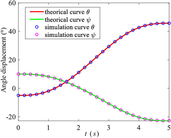
The theoretical curves for angular displacements (i.e.,
 $\theta$
and
 $\psi$
) of end-effector can be obtained by importing Eq. (16) into Matlab. As shown in Fig. 4, the theoretical curves of
 $\theta$
and
 $\psi$
are represented by red and green continuous lines, respectively. Meanwhile, importing the 3D model of this PM into Adams and taking the simulation time and step as 5 and 0.2 s, then the corresponding simulation curves of
 $\theta$
and
 $\psi$
, represented by blue and pink circles, are presented in Fig. 4. It can be seen that the theorical curves and simulation curves are almost completely consistent, which further prove that the correctness of the analytical kinematic model.
Comparison between theoretical curve in Matlab and simulation curve in Adams.

4. Analysis of good transmission orientation capability
4.1. Orientation parameters of the deviating output axis
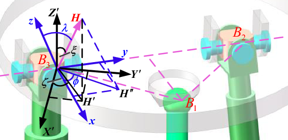
Since the axes of two rotations of end-effector are located in the plane of moving platform, the azimuth angle
 $\zeta$
and tilt angle
 $\xi$
can be used to describe the orientation of end output axis. The orientation capability of mechanism can be defined as the tilt range of output axis relative to the Z axis in the {f}. According to Ref. [Reference Liu, Wu, Wang and Boney20], asymmetry topological structure of mechanism will limit its own orientation capability. Consequently, to enhance orientation capacity of UPS-RPU-PU PM, the output axis of moving platform is designed as deviation type, that is, there is an offset angle
 $\lambda$
between output axis B
3
H and the normal direction of the moving platform presented in Fig. 5.
Orientation of output axis B 3 H attached to the moving platform in {m} and {m´}.

In Fig. 5, let the mobile coordinate frame
 $\{m'\}\colon \,\,B_{3}X'Y'Z'$
be always parallel to the fixed coordinate frame {f}, and that the projections of output axis B
3
H in planes
 $B_{3}X'Y'$
and
 $B_{3}xy$
are
 $B_{3}H'$
and
 $B_{3}H''$
, respectively.
 $\varphi$
and
 $\lambda$
are the azimuth angle and offset angle of B
3
H in the {m}, and that the azimuth and tilt angles of B
3
H in the
 $\{m'\}$
can be expressed as
 $\zeta$
and
 $\xi$
. Suppose the range of above orientation parameters to be
 $\phi \in [0,2{\unicode[Arial]{x03C0}} ), \lambda \in [0,{\unicode[Arial]{x03C0}} /2), \zeta \in [0,2{\unicode[Arial]{x03C0}} )$
, and
 $\xi \in [0,{\unicode[Arial]{x03C0}} /2)$
.
From Fig. 5, the unit vector of B 3 H in the {f} can be written as
 \begin{equation} \boldsymbol{n}_{{B_{3}}H}=\boldsymbol{M}\!\left(\textrm{s}\lambda \textrm{c}\phi,\textrm{s}\lambda \textrm{s}\phi,\textrm{c}\lambda \right)^{\textrm{T}}=\left(\textrm{s}\xi \textrm{c}\zeta,\textrm{s}\xi \textrm{s}\zeta,\textrm{c}\xi \right)^{\textrm{T}}, \end{equation}
where s and c represent sine and cosine functions, respectively.
Substituting Eq. (7) into Eq. (18) yields
 \begin{equation} \textrm{s}\lambda \textrm{c}\phi \textrm{c}\psi +\textrm{c}\lambda \textrm{s}\psi -\textrm{s}\xi \textrm{c}\zeta =0, \end{equation}
 \begin{equation} \left(\begin{array}{c@{\quad}c} \textrm{s}\lambda \textrm{c}\phi \textrm{s}\psi -\textrm{c}\lambda \textrm{c}\psi & \textrm{s}\lambda \textrm{s}\phi \\[5pt] \textrm{s}\lambda \textrm{s}\phi & \textrm{c}\lambda \textrm{c}\psi -\textrm{s}\lambda \textrm{c}\phi \textrm{s}\psi \end{array}\right)\left(\begin{array}{l} \textrm{s}\theta \\[5pt] \textrm{c}\theta \end{array}\right)=\left(\begin{array}{c} \textrm{s}\xi \textrm{s}\zeta \\[5pt] \textrm{c}\xi \end{array}\right). \end{equation}
When the orientation parameters, i.e.,
 $(\zeta,\xi,\phi,\lambda )$
, are known, the Euler angle
 $\psi$
of the moving platform can be expressed as
 \begin{equation} \begin{array}{l} \\[5pt] \psi =\left\{\begin{array}{l} 2{\arctan }\left(\dfrac{\textrm{c}\lambda \pm \sqrt{\textrm{c}^{2}\lambda +\textrm{s}^{2}\lambda \textrm{c}^{2}\phi -\textrm{s}^{2}\xi \textrm{c}^{2}\zeta }}{\textrm{s}\lambda \textrm{c}\phi +\textrm{s}\xi \textrm{c}\zeta }\right)\quad \quad \left(\textrm{s}\lambda \textrm{c}\phi +\textrm{s}\xi \textrm{c}\zeta \neq 0\right),\\[15pt] -2\!\arctan\!\left(\tan \lambda \textrm{c}\phi \right)\quad \quad \left(\textrm{s}\lambda \textrm{c}\phi +\textrm{s}\xi \textrm{c}\zeta =0\right). \end{array}\right. \end{array} \end{equation}
Obviously,
 $\psi$
has two solutions when
 $\cos ^{2}\lambda +\sin ^{2}\lambda \cos ^{2}\phi -\sin ^{2}\xi \cos ^{2}\zeta$
> 0. According to the engineering requirement, take the solution meet the condition: |
 $\psi$
|<π/2. Substitute
 $\psi$
into Eq. (20), then Euler angle
 $\theta$
is
 \begin{equation} \theta ={\arctan }2\left(\frac{\textrm{s}\xi \textrm{s}\zeta \!\left(\textrm{s}\lambda \textrm{c}\phi \textrm{s}\psi -\textrm{c}\lambda \textrm{c}\psi \right)+\textrm{c}\xi \textrm{s}\lambda \textrm{s}\phi }{\textrm{c}\xi \!\left(\textrm{c}\lambda \textrm{c}\psi -\textrm{s}\lambda \textrm{c}\phi \textrm{s}\psi \right)+\textrm{s}\xi \textrm{s}\zeta \textrm{s}\lambda \textrm{s}\phi }\right), \end{equation}
where arctan2(·) represents bivariate arctangent function.
The Euler angles (
 $\theta$
,
 $\psi$
) can be directly obtained through Eqs. (17) and (18), and then orientation matrix
M
is acquired accordingly. In other words, Eqs. (21) and (22) denote the analytical relation between the orientation parameters
 $(\zeta,\xi,\phi,\lambda )$
and Euler angles (
 $\theta$
,
 $\psi$
).
4.2. Motion/force transmission performance
The motion/force transmissibility is one of the most important factors affecting the working performance of PM. With the aid of screw theory, this paper establishes mathematical models of three indices, i.e., input transmission index (ITI), output transmission index (OTI), and LTI to evaluate motion/force transmissibility of the discussed mechanism [Reference Wang, Wu and Liu11].
The twist screw corresponding to the driving joint P
i
in the ith limb is known as input twist screw (ITS)
 $\boldsymbol{\$ }_{\textrm{ITS}}^{i}$
. Therefore, the ITS of each limb of UPS-RPU-PU PM in the {f} can be written as
 \begin{equation} \boldsymbol{\$ }_{\textrm{ITS}}^{i}=\left(\mathbf{0}_{3\times 1}^{\textrm{T}},\boldsymbol{w}_{i}^{\textrm{T}}\right)^{\textrm{T}}\!\quad\left(i =1,2,3\right). \end{equation}
The transmission wrench screw (TWS) of each limb is the increased CWS after rigidizing driving joint P. According to Ref. [Reference Wang, Wu and Liu11], TWS of each limb of this mechanism is pure force crossing point A
i
along
 $\boldsymbol{w}_{i}$
direction. Consequently, the TWS in the {f} can be expressed as
 \begin{equation} \boldsymbol{\$ }_{\textrm{TWS}}^{i}=\left(\boldsymbol{w}_{i}^{\textrm{T}},\left(\boldsymbol{A}_{i}\times \boldsymbol{w}_{i}\right)^{\textrm{T}}\right)\quad\left(i =1,2,3\right). \end{equation}
After locking the driving joints of the other two branches except the ith branch chain, the discussed PM is instantaneously degenerated into a single-DOF spatial linkage mechanism. So the output wrench screw (OTS) of the ith limb in the {f}, recorded as
 $\boldsymbol{\$ }_{\textrm{OTS}}^{i}$
, can be defined as the instantaneous twist screw of the single-DOF mechanism. On this basis, the calculation method of
 $\boldsymbol{\$ }_{\textrm{OTS}}^{i}$
can be summarized as: delete
 $\boldsymbol{\$ }_{\textrm{TWS}}^{i}$
from the 6 × 6 matrix composed of CWS in Eq. (6) and TWS in Eq. (24), and then solve the reciprocal screw for the remaining five screws, that is, the numerical solution of
 $\boldsymbol{\$ }_{\textrm{OTS}}^{i}$
in the {f}.
According to the definition in Ref. [Reference Wang, Chen and Wu16], the analytical formulae of ITI and OTI of each branch chain can be expressed as
 \begin{equation} \eta _{\textrm{ITI}}^{i}=\frac{\left| \boldsymbol{{\$ }^{i}_{\textrm{ITS}}}\circ \boldsymbol{\$ }^{i}_{\textrm{TWS}}\right| }{\left| \boldsymbol{{\$ }^{i}_{\textrm{ITS}}}\circ \boldsymbol{\$ }^{i}_{\textrm{TWS}}\right| _{\max }}\quad\left(i=1,2,3\right)\boldsymbol{,} \end{equation}
 \begin{equation} \eta _{\textrm{OTI}}^{i}=\frac{\left| \boldsymbol{{\$ }^{i}_{\textrm{OTS}}}\circ \boldsymbol{\$ }^{i}_{\textrm{TWS}}\right| }{\left| \boldsymbol{{\$ }^{i}_{\textrm{OTS}}}\circ \boldsymbol{\$ }^{i}_{\textrm{TWS}}\right| _{\max }}\quad\left(i=1,2,3\right)\boldsymbol{,} \end{equation}
where |·|max represents the potential maximum value of the reciprocal products between
 $\boldsymbol{\$ }_{\textrm{OTS}}^{i}$
and
 $\boldsymbol{\$ }_{\textrm{TWS}}^{i}$
, which can be obtained by using the method in Ref. [Reference Peng, Cheng, Che, Zheng and Cao21]; “
 $\circ$
” is the sign representing reciprocal product.
From Eqs. (23) and (24),
 $\boldsymbol{\$ }_{\textrm{ITS}}^{i}$
and
 $\boldsymbol{\$ }_{\textrm{TWS}}^{i}$
are always coaxial, that is, the
 $\eta _{\textrm{ITI}}^{i}$
is always equal to 1. Hence, the LTI of the UPS-RPU-PU PM can be expressed as
 \begin{equation} \eta _{\textrm{LTI}}=\min _{i=1,2,3}\!\left\{\eta _{\textrm{ITI}}^{i},\eta _{\textrm{OTI}}^{i}\right\}=\min _{i=1,2,3}\!\left\{\eta _{\textrm{OTI}}^{i}\right\}. \end{equation}
Based on aforementioned analysis, take
 $(Z_{B_{\text{3}}},\xi,\zeta )$
as output parameters of end-effector and give dimensional parameters
 $(l_{1},l_{2},l_{3},l_{4},\phi,\lambda )$
, and driving displacement q
i
and Euler angles
 $(\theta, \psi )$
can be obtained through Eqs. (12), (21), and (22), respectively. Then CWS, TWS, and OTS can be determined, accordingly. Finally, the
 $\eta _{\textrm{OTI}}^{i}$
and
 $\eta _{\textrm{LTI}}$
can be calculated from Eqs. (26) and (27). Overall, it can be conclude that
 $\eta _{\textrm{LTI}}$
can be expressed by
 $(Z_{{B_{3}}},\zeta,\xi )$
, i.e.,
 \begin{equation} \eta _{\textrm{LTI}}=\eta _{\textrm{LTI}}\!\left(Z_{{B_{3}}},\zeta,\xi \right). \end{equation}
4.3. Good transmission orientation capability
The reachable workspace of UPS-RPU-PU PM, known as
 $\Omega _{\textrm{rea}}$
, can be defined as the set composed of the reachable position
 $Z_{B_3}$
and orientation
 $(\zeta,\xi )$
of end-effector reference point B
3. According to topological structure of mechanism, any position and orientation
 $(Z_{B_3},\zeta,\xi )$
within
 $\Omega _{\textrm{Rea}}$
should meet the following constraints.
Constraint 1: The constraints of actuating displacement of each limb q i is
 \begin{equation} q_{\min }\leq q_{i}\leq q_{\max }\quad \left(i=1,2,3\right), \end{equation}
where q min and q max are lower and upper boundaries, respectively.
Constraint 2: Suppose
 $\theta _{i}$
and
 $\psi _{i}$
to be the swing angle of the first and the second axes in U
i
joint, respectively, clearly,
 $\theta _{i}=\theta, \psi _{i}=\psi$
(i = 2, 3). Therefore, the constraints of the oscillating angles for U
i
joints are
 \begin{equation} \left\{\begin{array}{l} \theta _{i}\leq \delta _{\textrm{U},\max },\\[5pt] \psi _{i}\leq \delta _{\textrm{U},\max }, \end{array}\right.\quad \left(i=1,2,3\right), \end{equation}
where
 $\delta _{\textrm{U},\max }$
is the upper boundaries of swing angles for U and S joints.
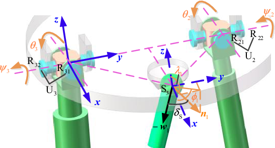
Constraint 3: In engineering application, the normal vector of spherical joint base is installed in offset, not perpendicular to the plane of moving platform. As presented in Fig. 6,
n
1 is the normal vector of S joint base, which can be written as
 $\boldsymbol{n}_{1}=(\!\sin \lambda _{1}\cos \phi _{1},\sin \lambda _{1}\sin \phi _{1},\cos \lambda _{1})^{\textrm{T}}$
in the {m}, where
 $\varphi$
1∈[0, 2π] and
 $\lambda$
1∈(π/2, π) are the azimuth angle and offset angle of
n
1, respectively. Consequently, the oscillating angle of S joint
 $\delta _{\textrm{S}}=\arccos (\!-\boldsymbol{n}_{1}^{\textrm{T}}\boldsymbol{M}^{\textrm{T}}\boldsymbol{w}_{1})$
, and the corresponding constraint is
 \begin{equation} \delta _{\textrm{S}}\leq \delta _{\textrm{S},\max }, \end{equation}
where
 $\delta _{\textrm{S},\max }$
are the upper boundaries of oscillating angle for spherical joint.
The diagram for installation and constraint of Spherical joint.

Constraint 4: For lower-mobility PMs, the interference between linkages can be efficiently avoided by reasonably selecting
 $\delta _{\textrm{U},\max }, \delta _{\textrm{S},\max }$
and designing distribution of limbs.
From Eqs. (25) to (26),
 $\eta _{\textrm{LTI}}$
of UPS-RPU-PU PM is only related to
 $\eta _{\textrm{OTI}}^{i}$
of the ith limb. In addition, the essence of
 $\eta _{\textrm{OTI}}^{i}$
is the absolute value of sine function for transmission angle in the ith limb (i.e., the complementary angle of the acute angle between
 $\boldsymbol{\$ }_{\textrm{TWS}}^{i}$
and
 $\boldsymbol{\$ }_{\textrm{OTI}}^{i}$
) [Reference Wu, Liu, Wang and Wang12]. Therefore, the larger the transmission angle of each driving limb, the better its motion/force transmission performance. For heavy-duty equipment, engineering experience shows that the minimum transmission angle is often set to be 45°–50° to ensure that such mechanism has good force transmissibility. On this basis, the allowable LTI can be taken as
 $[\eta ]=\sin 45^{\circ}\approx 0\textit{.}7$
.
According to Eq. (28), when
 $Z_{B_3}$
is taken as a fixed value,
 $Z_{0}, \eta _{\textrm{LTI}}$
is degenerated into a binary function, i.e.,
 $\eta _{\textrm{LTI}}=\eta _{\textrm{LTI}}(\zeta,\xi )$
. Based on this, the set composed of orientation
 $(\zeta,\xi )$
within
 $\Omega _{\textrm{Rea}}$
satisfying the condition
 $\min _{i=1,2,3}\{\eta _{\textrm{OTI}}^{i}\}=\eta _{\textrm{LTI}}\geq [\eta ]$
is defined as GTOW, recorded as
 $\Omega _{\textrm{GTOW}}$
, i.e.,
 \begin{equation} \Omega _{\textrm{GTOW}}=\left\{\left(\zeta,\xi \right)\boldsymbol{|}\eta _{\textrm{LTI}}\!\left(Z_{{B_{3}}},\zeta,\xi \right)\geq \left[\eta \right],\left(\zeta,\xi \right)\in \Omega _{\textrm{Rea}},Z_{{B_{3}}}=Z_{0}\right\}. \end{equation}
Plot the maximum inscribed circle (MIC) of the GTOW, the set composed of orientation
 $(\zeta,\xi )$
within MIC is defined as regular good transmission orientation workspace (RTOW), denoted as
 $\Omega _{\textrm{RTOW}}$
, and the corresponding radius represents good transmission orientation capacity (GTOC), i.e.,
 \begin{equation} \xi _{\textrm{GTOC}}=\min \!\left\{\xi \,\left| \,\eta _{\textrm{LTI}}\right.\!\left(Z_{{B_{3}}},\zeta,\xi \right)=\left[\eta \right],\,\forall \zeta \in \left[0,2{\unicode[Arial]{x03C0}} \right),Z_{{B_{3}}}=Z_{0}\right\}. \end{equation}
 $Z_{B_3}$
and
 $(\zeta,\xi )$
are completely independent, in other words,
 $Z_{B_3}$
has little influence on GTOC. On this basis, the GTOW section height
 $Z_{B_3}$
can be set as a fixed value in the following research.
Since the
 $\eta _{\textrm{LTI}}$
can only reflect motion/force transmissibility of mechanism under a certain instantaneous pose, calculate the mean, and standard deviation of the corresponding LTI for all pose within
 $\Omega _{\textrm{RTOW}}$
, we can get
 \begin{equation} \left\{\begin{array}{l} \eta _{\textrm{GTI}}=\dfrac{\int _{0}^{2{\unicode[Arial]{x03C0}} }\int _{0}^{\xi _{\textrm{GTOC}}}\eta _{\textrm{LTI}}\!\left(\zeta,\xi \right)\sin \xi \textrm{d}\zeta \textrm{d}\xi }{2{\unicode[Arial]{x03C0}}\!\left(1-\cos \xi _{\textrm{GTOC}}\right)},\\[15pt] \sigma _{\eta }=\sqrt{\dfrac{\int _{0}^{2{\unicode[Arial]{x03C0}} }\int _{0}^{\xi _{\textrm{GTOC}}}\!\left(\eta _{\textrm{LTI}}-\eta _{\textrm{GTI}}\right)^{2}\sin \xi \textrm{d}\zeta \textrm{d}\xi }{2{\unicode[Arial]{x03C0}} \!\left(1-\cos \xi _{\textrm{GTOC}}\right)}}. \end{array}\right. \end{equation}
Performance indices
 $\eta _{\textrm{GTI}}$
and
 $\sigma _{\eta }$
, known as GTI and transmission fluctuation index, can quantitively describe kinematic performance of mechanism within its whole
 $\Omega _{\textrm{RTOW}}$
. Specifically,
 $\eta _{\textrm{GTI}}$
is closely related to motion/force transmission performance of mechanism within whole
 $\Omega _{\textrm{RTOW}}$
, whose range is form 0 to 1, and that the closer
 $\eta _{\textrm{GTI}}$
is to 1, the better motion/force transmissibility is. While
 $\sigma _{\eta }$
directly reflects the transmission fluctuation of motion and force in whole
 $\Omega _{\textrm{RTOW}}$
, the closer
 $\sigma _{\eta }$
is to 0, the more stable the transmissibility is.
4.4. Example of good transmission orientation workspace analysis
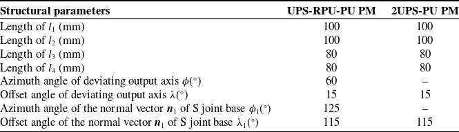
The following gives a comparative case of kinematic performance of UPS-RPU-PU and 2UPS-PU (shown in Fig. 7) PMs. For the sake of fairness, the structural parameters of two PMs are included in Table III. It is worth noting that since 2UPS-PU PM is characterized by plane-symmetric topological structure, the deviating output axis of end-effector has only offset angle
 $\lambda$
and the normal vector of two S joints base only have offset angles
 $\lambda _{1}$
as well. The lower and upper boundaries of the actuating displacement q
i
(i = 1, 2) are q
min = 350 mm and q
max = 650 mm. The upper boundaries of the oscillating angles
 $\delta$
S, max and
 $\delta$
U, max for the S and U joints are 45° and 65°, respectively. The search range of T&T angles
 $\zeta$
and
 $\xi$
are [0, 360°] and [0, 60°], respectively. Since the translation along Z axis Z
B
3 has no influence on transmission performance index [Reference Xie, Liu and Li7], it can be taken as a fixed value of 450 mm.
Schematic diagram 2UPS-PU parallel mechanism.

Structural parameters of mechanisms.

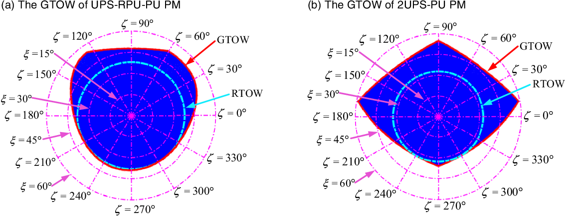
According to aforementioned known parameters, Fig. 8 presents the point cloud diagrams of GTOWs of two mechanisms through numerical search method, in which polar angle and polar diameter represent azimuth angle
 $\zeta$
and tilt angle
 $\xi$
, respectively. The blue region represents GTOW and the white region is the unreachable poses of end-effector caused by the structure constraints in Eqs. (29)–(31). Moreover, the boundary curve of GTOW, represented by the red continuous line, is obtained through coordinate search method and dichotomy, and its MIC is represented by the cyan dot line. From Eq. (33), the region enclosed by cyan dot line is the RTOW, whose radius is the
 $\xi$
GTOC. Obviously, the GTOW of UPS-RPU-PU is spatial asymmetry, while that of 2UPS-PU is symmetric with respect to
 $\zeta$
= 90°, which is consistent with their own topological structure.
The point cloud of GTOW of two mechanisms.

To quantitively compare kinematic performance, the corresponding performance indices are included in Table IV. In this table, the number of points,
 $\eta _{\textrm{GTI}}$
and
 $\sigma _{\eta }$
of the discussed two mechanisms are relatively close. The indices
 $\eta _{\textrm{GTI}}$
and
 $\sigma _{\eta }$
indicates that two mechanism have good and stable motion/force transmission performance in their own GTOWs. The
 $\xi$
GTOC of UPS-RPU-PU PM is obviously better than that of 2UPS-PU PM, which means that the asymmetric UPS-RPU-PU PM designed in this paper has greater advantage in some engineering occasions requiring large rotational capability.
The performance indices of GTOW.

5. Dimensional synthesis model and method with optimal orientation capacity
5.1. Decision variables and objective function
As the dimensional parameters of mechanisms are scaled to a factor, the performance indices do not change. Consequently, the length l
1 can be preset, and dimensional parameters
 $(l_{2},l_{3},l_{4})$
and azimuth and offset angles
 $(\phi,\lambda )$
of deviating output axis B
3
H can be taken as design parameters. In addition, the rotation range of S joint and the orientation parameters (
 $\varphi$
1,
 $\lambda$
1) of normal vector of S joint base can also affect orientation capacity. Therefore, the decision variables of this dimensional optimization problem can be written as
 \begin{equation} \boldsymbol{x}=\left(x_{1},x_{2},\cdots,x_{7}\right)^{\textrm{T}}=\left(l_{2},l_{3},l_{4},\phi,\lambda,\phi _{1},\lambda _{1}\right)^{\textrm{T}}. \end{equation}
To meet some working state requiring large tilt angle (such as cutting, multidimensional force loading, and joint rehabilitation training), designers expect UPS-RPU-PU PM to achieve maximum orientation capability. Thus, the objective function of this dimensional synthesis model can be formulated as
 \begin{equation} \max \,\,f\!\left(\boldsymbol{x}\right)=\xi _{\textrm{GTOC}}\!\left(\boldsymbol{x}\right). \end{equation}
5.2. Constraints
Designers usually expect the proposed PM to have good and stable motion/force transmission performance; therefore, the mechanism should have a GTI higher than the allowable value, and a
 $\sigma _{\eta }$
as small as possible. The following constraints are introduced:
 \begin{equation} \left\{\begin{array}{l} g_{1}\!\left(\boldsymbol{x}\right)=0.8-\eta _{\textrm{GTI}}\leq 0,\\[5pt] g_{2}\!\left(\boldsymbol{x}\right)=\sigma _{\eta }-0.1\leq 0. \end{array}\right. \end{equation}
Notice that the structure constraints of the mechanism have been considered in Eqs. (29)–(31), hence the dimensional synthesis model of UPS-RPU-PU PM belongs to an expensive constrained optimal problem, which needs to be solved with the aid of intelligence algorithms.
5.3. Differential evolution algorithm
A large number of studies indicate that DE algorithm outperforms other intelligent algorithms (such as GA, PSO, and ABC algorithms) in global optimization capability and high convergence speed and computational performances [Reference Das, Mullick and Suganthan22]. In this paper, DE algorithm is employed to solve this dimensional synthesis model.
The specific process of DE algorithm for solving optimization problems is elaborated in Ref. [Reference Das, Mullick and Suganthan22], thus being omitted here. The computational performance of DE algorithm are closely related to the following four control parameter, i.e., maximum generation number T, population size N
P, scaling factor F, and crossover factor C
R. Suppose the population at the t-th generation to be
 $\boldsymbol{X}^{(t)}=\{\boldsymbol{x}_{1}^{(t)},\cdots,\boldsymbol{x}_{N_{\textrm{P}}}^{(t)}\}$
(t = 0, 1,···, T), the corresponding individual to be
 $\boldsymbol{x}_{n}^{(t)}=(x_{n,\textbf{1}}^{(t)},\cdots,x_{n,\textbf{7}}^{(t)})^{\textrm{T}}$
(n = 1, 2,···, N
P), and the current optimal one to be
 $\boldsymbol{x}_{\textrm{best}}^{(t)}$
. This paper utilizes the DE/rand/1/bin version to create mutant individual
 $\boldsymbol{y}_{n}^{(t)}$
and trial individual
 $\boldsymbol{z}_{n}^{(t)}$
. Finally, the better of
 $\boldsymbol{y}_{n}^{(t)}$
and
 $\boldsymbol{z}_{n}^{(t)}$
is retained as the next offspring individual
 $\boldsymbol{x}_{n}^{(t+1)}$
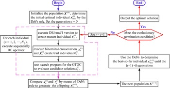
. Additionally, the feasibility-based rule, proposed by Deb [Reference Deb23], is applied to handle the inequality constraints in Eq. (37), and the detailed handling steps have been presented in Ref. [Reference Che, Chen, Jiang, Du and Wen24]. Therefore, the flow chart of DE algorithm with constraints handling technical for solving dimensional synthesis model in Sections 5.1 and 5.2 is illustrated in Fig. 9.
The flow chart of DE algorithm for solving dimensional synthesis model of UPS-RPU-PU PM.

5.4. Parameters setting
The length of l
1 and the section height of workspace
 $Z_{B_3}$
are taken as 100 and 450 mm, respectively. The control parameters of DE algorithm are N
P = 30, F = 0.5, C
R = 0.85, and T = 100. The range of decision variables are set as
 $\boldsymbol{x}_{\min }=(50\,\textrm{mm},40\,\textrm{mm},40\,\textrm{mm},0^{\circ},-20^{\circ},0^{\circ},90^{\circ})^{\textrm{T}}$
and
 $\boldsymbol{x}_{\max }=(200\,\textrm{mm},160\,\textrm{mm},160\,\textrm{mm},360^{\circ},20^{\circ},\,$
 $360^{\circ},\,180^{\circ})^{\textrm{T}}$
, respectively. Search step
 $\delta$
is taken as 1°.
5.5. Analysis of optimization design results
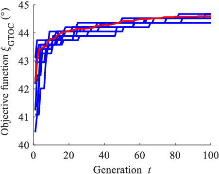
After performing independently DE algorithm for 10 times, the generation curves of objective function are plotted in Fig. 10. Each blue line represents the optimization curve of objective function for the DE algorithm running once independently, and the red is the average generation curve of this algorithm running 10 times. It can be seen from Fig. 10 that the optimal solutions of each curve are very close and the convergence trend of 11 curves is consistent, which demonstrates that DE algorithm has good stability and reliability in solving aforementioned dimensional synthesis model.
The generation curves of DE algorithm.

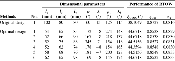
The optimal dimensional parameters and corresponding performance indices are included in Table V. For comparison, the original dimensional parameters are also included in the table. As can be seen from Table V, the maximum
 $\xi$
GTOC is increased to 44.6718° with the optimized mechanism dimensional parameters, i.e., the range of tilt angle
 $\xi$
is approximately [−45°, 45°], which can meet some engineering occasions with larger orientation capacity (such as surface parts machining, multidimensional force loading, rehabilitation training devices). Compared with original dimensional parameters,
 $\eta$
GTI and
 $\sigma$
 $_{\eta}$
are basically unchanged and meet the constrained functions in Eq. (37). On this basis, it can be concluded that the model and method of mechanism optimization design are feasible and effective. Furthermore, the performance indices corresponding to six groups of optimal dimensional parameters are very close, which further indicates that the six groups of optimization results (i.e., near-optimization solutions) are close to the global optimization solutions
 $\boldsymbol{x}_{\textrm{best}}^{(t)}$
of this optimization problem.
Results comparison between original and optimal dimensional parameters.

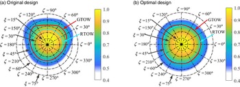
Taking the sixth group of dimensional parameter in Table V as an example, Fig. 11 presents the performance atlases of GTOWs corresponding to the two groups of dimensional parameters in Table V. Similarly, the polar angle and polar diameter represent orientation angles
 $\zeta$
and
 $\xi$
, and the white region is unreachable poses of end-effector caused by the structure constraints in Eqs. (29)–(31). The red continuous line is the contour corresponding to
 $\eta _{\textrm{LTI}}=[\eta ]=0\textit{.}7$
, and its MIC is expressed by the cyan-dotted line. According to the definitions in Section 4.3, the region, enclosed by the red continuous line and the cyan-dotted line, are
 $\Omega _{\textrm{GTOW}}$
and
 $\Omega _{\textrm{RTOW}}$
, respectively. From Fig. 11(a), there are no holes in the GTOW of the mechanism with original dimensional parameters, and the boundary curve is smooth and has no abrupt point. However, the GTOW of the original mechanism is biased towards side of
 $\zeta$
= 90°, which results in insufficient use for
 $\xi$
GTOC. In Figs. 11(b), there exists still no holes in the GTOW of the optimized mechanism, and the appearance is better. Additionally, there are more points on the boundary of RTOW tangent to that of GTOW, and some of them are of symmetry, which indicates that
 $\xi$
GTOC of optimized mechanism has been significantly improved.
GTOW of the UPS-RPU-PU PM with defined section height (
 $Z_{\textit{B}_3}$
= 450 mm).

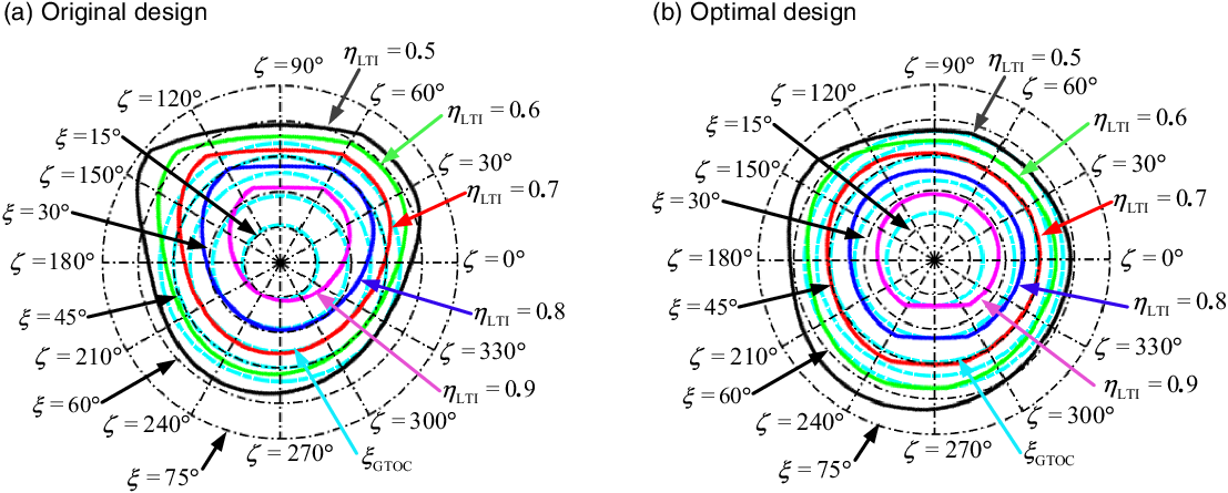
When LTI is taken as 0.5–0.9, the LTI contours of the two mechanisms in Table V are shown in Fig. 12. From Eqs. (25)–(27), when
 $\eta$
LTI is equal to 0 or close to 0, the output transmission singularity will happen in the discussed mechanism. Consequently, it can be inferred that all poses (
 $\zeta$
,
 $\xi$
) within LTI contours in Fig. 12 are far away from the singular boundaries. As can be seen from Fig. 12(a), when LTI is taken as 0.9, the corresponding
 $\xi$
GTOC is poor and even may disappear, since the GTOW is biased towards the side of
 $\zeta$
= 90°. In Fig. 12(b), the GTOW of the optimized mechanism tends to the side of
 $\zeta$
= 270° on the basis of the original; in this case, the
 $\xi$
GTOC always exists when LTI is equal to 0.9.
LTI-contour atlases of the two mechanisms.

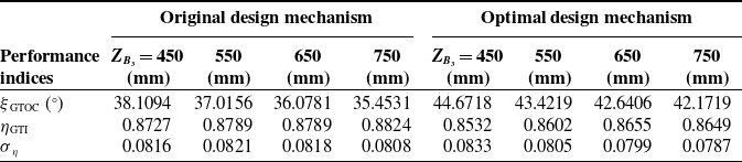
To quantitatively compare performance of GTOWs at different workspace sections, set
 $Z_{B_3}$
to be 450, 550, 650, and 750 mm, and the corresponding performance indices are given in Table VI. From this table, the
 $\xi$
GTOC of each section has been significantly improved after the mechanism is optimized. In other words, the optimized mechanism is of larger orientation capability within the whole
 $\Omega _{\textrm{rea}}$
. For the other two performance indices, both
 $\eta _{\textrm{GTI}}$
and
 $\sigma _{\eta }$
are reduced, but
 $\eta _{\textrm{GTI}}$
still meets constraints in Eq. (37). Moreover, it can be found that performance indices at different sections of two mechanism in Table VI really have only minor changes, which further demonstrates that the decoupled
 $Z_{B_3}$
has little influence on GTOW.
Performance indices of GTOWs at different sections.

The virtual prototype of hydraulic support test-bed.

6. Virtual prototype design and application
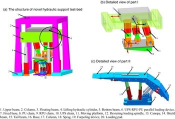
Hydraulic support test bed is the most important equipment to inspect the reliability and safety for hydraulic support, whose critical task is to investigate the various mechanical performance of hydraulic support under the mine through the loading test. Combined with references analysis and engineering survey, existing test beds exhibit three main technology issues: (I) imperfect external loading technology; (II) no stepless height adjustment; (III) no rotational loading capacity [Reference Wang25]. Therefore, a novel hydraulic support test bed is designed, in which the optimized UPS-RPU-PU PM is utilized as the actuating loading device.
As presented in Fig. 13(a), the main structure of the novel hydraulic support test bed is three-bottom and four-column type. The upper beam, four columns, and bottom beam are welded to form a fixed frame, while the floating beam can move along slide rail on each column through the four lifting hydraulic cylinders. The UPS-RPU-PU parallel loading device is installed on the floating beam (shown in Fig. 13(b)), which can move along Y axis to meet the loading for different parts of hydraulic support. For easy calibration, the floating beam adopts the stepped height adjustment of 500 mm per stage through the solenoid control valve, and the translation along Z axis of parallel loading device can realize stepless height adjustment to adapt to the test height of all tested supports. To better guild engineering application, a 4-cloumn standing shield hydraulic support (shown in Fig 13(c)), named as ZZ9200/24/ 50, is selected as tested object, where “ZZ” is the support type code, “9200” means the working resistance (kN), “24” and “50” mean the minimum and maximum support heights (dm), respectively.
The loading test of hydraulic support mainly focuses on main structure parts, namely canopy, shield beam, column, and base. Among them, the test of columns is carried out separately on the special equipment. Fig. 13(a) is the legend for transverse intermediate loading of canopy. During the test, contract sprag and forpoling device, adjust floating beam to an appropriate height through the four lifting hydraulic cylinders, and then place the tested hydraulic support in a suitable position on the workbench. With the aid of three actuating limbs, the parallel loading head is in direct contact with the loading pad, and then the corresponding compression condition of the hydraulic support under the mine can be simulated. Different mechanical property can be tested by changing the position of loading pad, and the methods of other loading items are elaborated in Ref. [Reference Zhang, Ren, He, Bian, Li and Ma26], thus being omitted here.
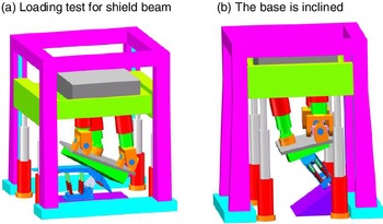
The lager orientation capability of the optimized mechanism can accomplish the external loading for shield beam and large inclination hydraulic support, and corresponding legends are given in Fig. 14. To facilitate determining the orientation angles of deviating loading spindle, the plane in contact with the surface of tested supports is designed to be perpendicular to the end output axis B 3 H. In this way, the azimuth and tilt angles can be directly obtained according to the orientation of tested parts. Consequently, measured in Solidworks software, the orientation parameter of UPS-RPU-PU under the two conditions in Fig. 14 are (0°, 43°) and (20°, 35°), respectively. According to GTOW performance atlas in Fig. 11(b), the above orientation parameters are all within GTOW, which indicates parallel loading device has good kinematic performance under loading test for shield beam and large inclination hydraulic supports.
Partial loading test items requiring large orientation capacity.

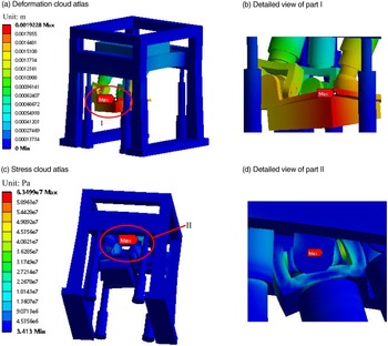
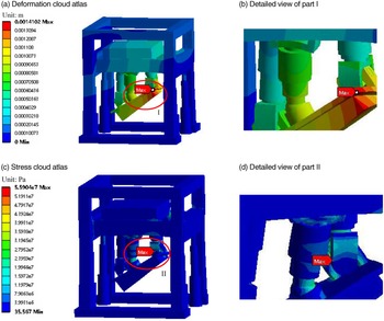
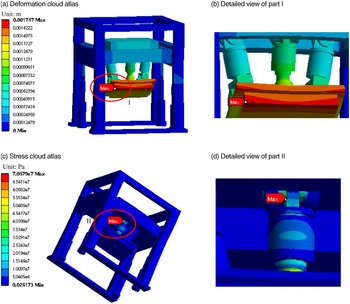
For such large and heavy-duty equipment, the analysis for stiffness and strength is essential. Using Ansys software as a solving tool, this paper analyze the stiffness and strength of novel hydraulic support test bed under the above three typical loading conditions. Q460 is selected as main structural material of novel test bed, and 10 MN is applied to the contact area between deviating loading head and tested support. Finally, the deformation and stress cloud atlases are presented in Figs. 15–17.
Finite element analysis of transverse intermediate loading of canopy.

Finite element analysis of shield beam loading.

Finite element analysis of large inclination hydraulic support loading.

In Figs. 15(a)–17(a), the maximum deformation of test bed under three typical working conditions are 1.923, 1.410, and 1.744 mm, respectively. Obviously, the overall deformation conforms to the requirement of engineering application. Moreover, the maximum stress corresponding to the three conditions can be known from Figs. 15(b)–17(b), which all meet the yield limit (i.e., 460 MPa) of selected material. Notice that the points with maximum stress in Figs. 15(b) and 16(b) are inside the corresponding parts. Aforementioned analysis indicates that the novel hydraulic support test bed has good stiffness and strength. From the above engineering case, it can be concluded that optimized asymmetric UPS-RPU-PU PM has a good application prospect in developing a novel hydraulic support test bed.
7. Conclusions
An asymmetry 2R1T PM with zero-coupling degree is proposed, whose analytical forward displacement solutions are addressed by the means of vector method. The numerical example and motion simulation verify the correctness of kinematic model. The orientation of deviating output axis is depicted with the aid of azimuth and tilt angles and the analytical relation between orientation parameters and Euler angles is established. Using screw theory as the mathematical tool, the analytical formulas of ITI, OTI, and LTI are deduced, and the definitions and calculation methods of GTOW, GTOC, GTI, and the standard deviation
 $\sigma$
 $_{\eta}$
are given. Subsequently, a comparative case on kinematic performance of UPS-RPU-PU and 2UPS-PU PMs demonstrates that the former has a greater advantage in some engineering occasions requiring large rotational capability. On this basis, a constrained optimization model is constructed to formulate dimensional optimization problem on maximizing GTOC, which is solved by DE algorithm with constraints handling technical. According to the optimal dimensional parameters, a novel hydraulic support test bed, taking this mechanism as loading device, is designed in this paper. The finite element analysis results demonstrate that the optimized UPS-RPU-PU PM is suitable for loading device of novel multifunctional hydraulic support test bed.
Author contributions
Siyang Peng designed the novel 1T2R type UPS-RPU-PU parallel mechanism and conceived this paper, Zhihong Cheng and Linxian Che are both corresponding authors and verified the correctness of the data, Song Cui modified some inappropriate English expressions, and Zujin Jin guided Siyang Peng to finish simulation analysis.
Declaration of competing interest
The authors declared that they have no conflicts of interest to this work. We declare that we do not have any commercial or associative interest that represents a conflict of interest in connection with work submitted.
Financial support
This work was sponsored by the National Key R&D Program of China (Grant No. 2018YFB1308303), the Natural Science Foundation of Chongqing, China (Grant No. cstc2020jcyj-msxmX0074), and Science and Technology Research Project of Chongqing Municipal Education Commission, China (Grant No. KJZD-K202101001).