Introduction
Fogging occurs when the hot water vapor condenses onto a cold surface to form discrete and dispersed light-diffusing tiny droplets and when the surface temperature is below the dew point of the surrounding air [Reference Nuraje, Asmatulu, Cohen and Rubner1, Reference Chang, Huang, Chang, Don, Chen and Cheng2, Reference Yang, Wang, Yang and Cai3]. Fogging is quite common and often causes trouble to people in day-to-day life. To solve the problem, we can fabricate a coating, which is wetted by water completely and instantaneously (superhydrophilicity: water contact angle < 5° within 0.5 s or less) [Reference Cebeci, Wu, Zhai, Cohen and Rubner4, Reference Xu and He5] or which completely resists wetting by water (superhydrophobicity: water contact angle > 150° and very low sliding angle < 5°; < 6-μL droplets) [Reference Lafuma and Quere6, Reference Deng, Mammen, Zhao, Lellig, Müllen, Li, Butt and Vollmer7]. To obtain a highly transparent surface, we should construct antireflective (AR) coatings. Nowadays, AR coatings/films have been attracting much attention for their applications in solar cells, optical devices, and display devices as a result of their ability to enhance transmittance and remove ghost images [Reference Buskens, Burghoorn, Mourad and Vroon8, Reference Mazur, Wojcieszak, Kaczmarek, Domaradzki, Song, Gibson, Placido, Mazur, Kalisz and Poniedzialek9]. An ideal AR coating should match the following two conditions [Reference Macleod10]: (i) n c = (n a × n s)1/2, reflection will be suppressed at the wavelength near the quarter-wavelength optical thickness of the coating (quarter-wave coating), where n a and n s are the refractive indices of the air (n a = 1.00) and the substrate, respectively. (ii) d = λ/4n c, d is the thickness of the coating, λ is the wavelength of incident light, and n c is the refractive index of coating. Nanoporous films with a low refractive index (approximately 1.22) and a quarter-wave coating are often used as AR films and coatings on glass or transparent plastic substrates with a refractive index of approximately 1.5 [Reference Buskens, Burghoorn, Mourad and Vroon8, Reference Zhang, Sato, Taguchi, Einaga, Murakami and Fujishima11]. Antifogging (AF) and AR coatings can maintain good visibility at all times, even in extreme climates with high temperature and humidity. Therefore, their preparation is becoming a subject of intense study for scientists and engineers [Reference Mazur, Wojcieszak, Kaczmarek, Domaradzki, Song, Gibson, Placido, Mazur, Kalisz and Poniedzialek9, Reference Yao, He, Geng and Ren12]. Various methods, such as layer-by-layer (LbL) assembly, dip-coating, spin-coating, spray-coating, and chemical modification, are often adopted in building antireflection [Reference Buskens, Burghoorn, Mourad and Vroon8, Reference Mazur, Wojcieszak, Kaczmarek, Domaradzki, Song, Gibson, Placido, Mazur, Kalisz and Poniedzialek9, Reference Yao, He, Geng and Ren12, Reference You, Lee, Lee, Kim and Byeon13], in self-cleaning (SC) [Reference Zhang, Sato, Taguchi, Einaga, Murakami and Fujishima11, Reference Jin, Ke, Jiang, Zhu, Cheng and Zhang14, Reference Liu, Li, Hou and Guo15, Reference Thompson, Fleming and Zou16], and in the preparation for AF [Reference Xu and He5, Reference Thompson, Fleming and Zou16, Reference Shang and Zhou17, Reference Hsu, Huang, Huang, Hu, Tsao and Kang18, Reference Howarter and Youngblood19].
Electrostatic LbL self-assembly, which was first reported by Iler in 1966 [Reference Iler20], is a simple, effective, and inexpensive method to fabricate various kinds of coatings [Reference Richardson, Cui, Björnmalm, Braunger, Ejima and Caruso21, Reference Zhang, Vlemincq, Ramirez Wong, Magnin, Glinel, Demoustier-Champagne and Jonas22, Reference Decher23]. To greatly improve the efficiency of an assembly process, Merrill and Sun [Reference Merrill and Sun24] first adopted the spin-spray layer-by-layer (SSLbL) assembly method. In this article, we have employed a modified SSLbL assembly method to rapidly produce thin coatings. During a spin state, the coatings were blown dry with hot air to speed up the LbL assembly process. We called this spray-spin-blow layer-by-layer (SSBLbL) assembly. While both processes are simple, rapid, and highly efficient methods to produce ultrathin coating [Reference Gittleson, Hwang, Ryu, Hashmi, Hwang, Goh and Taylor25, Reference Ma, Soroush, Van Anh Luong, Brennan, Rahaman, Asadishad and Tufenkji26], they also reduce the consumption of materials [Reference Merrill and Sun24, Reference Salomäki, Peltonen and Kankare27]. ZrO2 and SiO2 nanoparticles (NPs) were designed, synthesized, and utilized as building materials. They are of great interest due to their wide applications in almost all fields of industry. They are known as chemically stable, nontoxic, and eco-friendly NPs, and in addition, they are inexpensive and abundant in the nature. Thus, they are used in practically all fields of science and engineering and in everyday life as well.
In this work, we attempt to demonstrate that stable AF, AR, and SC coatings can be easily and quickly fabricated onto glass substrates using a spray-spin-blow LbL assembly method. This consisted of alternatingly applying three bilayers of positively charged ZrO2 NPs and negatively charged SiO2 NPs. The layers were firmly and quickly bound together via electrostatic interactions. The SSBLbL method is powerful yet simple, practical, and easy-to-use, and enables a high-throughput. The major advantage of the method is a dramatically reduced processing time needed for the multilayer formation, and the consumption of materials [Reference Merrill and Sun24, Reference Salomäki, Peltonen and Kankare27]. The high-temperature calcination can remove organics and impurities of the surface, promote the formation of stable siloxane bridges along with enhanced mechanical stability and adhesion to the substrates, and introduce three-dimensional (3D) nanoporous networks in the coating along with hydrophilicity improvement [Reference Cebeci, Wu, Zhai, Cohen and Rubner4]. These are essential features required for AF, AR, and SC coatings. As investigated in previous studies, such multifunctional coatings fabricated by SSBLbL electrostatic assembly of alternating positively charged ZrO2 NPs and negatively charged SiO2 NPs, exhibiting excellent superhydrophilic, AF, AR, and SC properties, have not yet been reported. Preparation of these multifunctional coatings should become a focus of research due to its potential and promising applications in various fields.
Results and discussion
NP morphology and structure, and zeta potential measurements
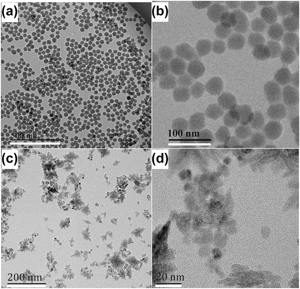
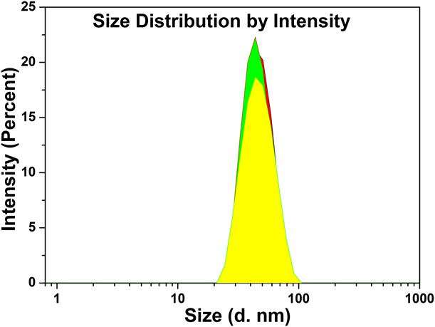
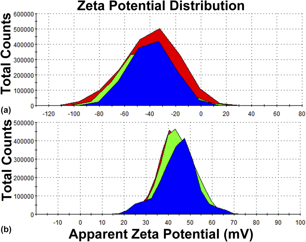
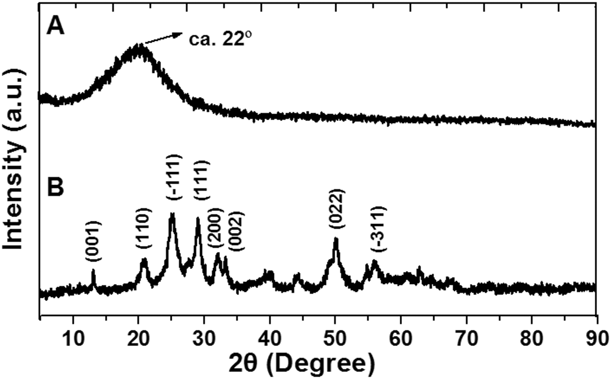
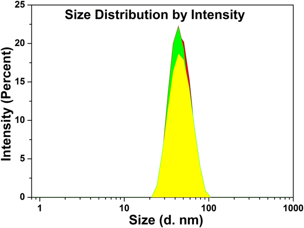
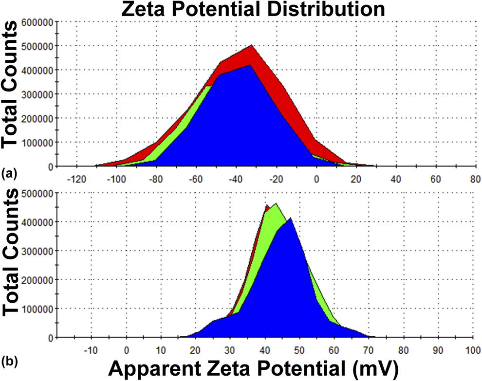
The microstructure and morphology of SiO2 and ZrO2 NPs were characterized by a transmission electron microscope (TEM); the particle size and morphology are of great importance for the performance of the coatings. As shown in Figs. 1(a) and 1(b), the SiO2 particles with uniform shape are monodisperse spheres of average diameter of approximately 45 nm. For comparison, we also used a Zetasizer Nano-ZS (Malvern instruments, Malvern, U.K.) to measure the same sample. The size of the SiO2 NPs [44.6 nm; see Fig. 2], polydispersity index (PDI) = 0.047, and zeta potential [−40.9 mV; Fig. 3(a)] were obtained and these data were measured in triplicate for accuracy. It was noted that the data from the Zetasizer Nano-ZS instrument were in agreement with the TEM results. The morphologies of the ZrO2 NPs characterized by TEM are shown in Figs. 1(c) and 1(d), from which we can see clearly that ZrO2 with good dispersion in nanoscale particles are also dispersed well. The shape of ZrO2 NPs in granular form is not as regular as that of spherical SiO2 NPs. The crystalline phase structures of SiO2 and ZrO2 NPs were determined by X-ray powder diffraction (XRD), as shown in Fig. 4. The results demonstrated that silica NPs had a typical characteristic amorphous peak [approximately 22°; see Fig. 4(a)], and zirconia was a structure of the typical monoclinic phase, as shown in Fig. 4(b). The zeta potentials of SiO2 and ZrO2 NPs were measured at 25 °C with a Zetasizer Nano-ZS instrument. It is an essential parameter for the characterization of the stability of an NP solution. A minimum of ±30 mV zeta potential value is required for indication of stable nanosol [Reference Jacobs and Müller28]. The SiO2 and ZrO2 had ζ-potential of −40.9 mV and +43.3 mV, respectively [see Figs. 3(a) and 3(b)].
TEM images of NPs of (a) SiO2 and (c) ZrO2, (b) and (d) are magnified views of (a) and (c), respectively. The scale bar in (a), (b), (c), and (d) is 500, 100, 200, and 20 nm, respectively.

Particle size graph of SiO2 NPs (mean value: 44.6 nm, PDI, 0.047).
Zeta potential graphs of (a) SiO2 NPs (mean value: −40.9 mV) and (b) ZrO2 NPs (mean value: +43.3 mV).
XRD patterns of (a) SiO2 and (b) ZrO2 NPs calcined at 520 °C.

ZrO2/SiO2 multilayer assembly and calcination of the coatings
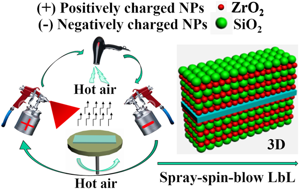
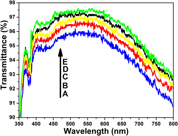
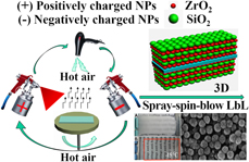
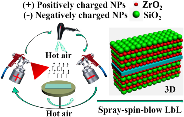
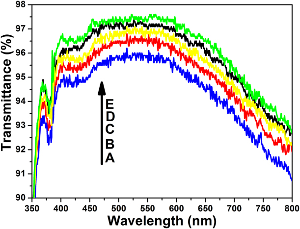
Multifunctional AF coatings can be readily fabricated from SSBLbL assembled films of positively charged ZrO2 and negatively charged SiO2 NPs. They are bound firmly together via electrostatic interactions. The concentration of both ZrO2 and SiO2 NP solutions was 0.8 mg/mL, with reference to previous studies [Reference Merrill and Sun24, Reference Gittleson, Hwang, Ryu, Hashmi, Hwang, Goh and Taylor25, Reference Ma, Soroush, Van Anh Luong, Brennan, Rahaman, Asadishad and Tufenkji26]. The positively charged ZrO2 (+43.3 mV) and negatively charged SiO2 solutions (−40.9 mV) were alternately sprayed on the spinning substrate, followed by blowing dry hot air after each step (see the schematic diagram in Fig. 5). Finally, the as-prepared coatings were calcined (heating rate: 2 °C/min) in a muffle furnace for 2.5 h. For long-term applications, they need to have excellent adhesion to the underlying substrates and good mechanical durability for daily use. Hence, high-temperature calcination is used for this purpose. The high-temperature treatment can fuse the NPs with one another and with glass substrates via the formation of stable siloxane bridges. After this treatment, the mechanical stability of the resultant coatings can be increased tremendously along with hydrophilicity improvement. In order to create an ideal AR coating with permanent AF properties, we investigated the effects of the number of deposited bilayers and different calcination temperatures. The preferred number of bilayers in an assembly was three, which will be described below in detail. To assess the effects of calcination temperatures on the transmittance and superhydrophilicity of the coatings, we prepared a series of coatings with three bilayers, which were calcined in a muffle furnace at 400, 440, 480, 520, and 560 °C for 2.5 h. As seen in Fig. 6, compared with the spectra (380–780 nm) of a bare glass (90.6% in transmittance), the average transmittance values of the coatings at different calcination temperatures were approximately 95.4%, 95.9%, 96.3%, 96.7%, and 96.8%, respectively. No apparent difference in transmittance (less than 1.4%) was observed when the temperature was increased from 400 to 560 °C. In the water contact angle (WCA) test, all the coatings formed at different calcination temperatures exhibited excellent superhydrophilicity (close to 0°, <0.04 s). This was because the high-temperature calcination (more than 400 °C) could burn out organics and impurities from the substrate surface, and retain hydrophilic inorganic materials and a 3D nanoporous network texture on the surface. Owing to the temperature of more than approximately 560 °C, glass can undergo thermal deformation. For rapid and high-efficiency preparation, the temperature of 520 °C was chosen as an optimum temperature in all the following experiments. The ZrO2/SiO2 coatings were fabricated with the ZrO2 coating as the first layer; after three bilayer stacks on each side, the ZrO2/SiO2 coatings were then calcined at 520 °C for 2.5 h. For comparison, the SiO2/ZrO2 coatings (the SiO2 coating was the first layer) were also prepared under the same conditions. After various performance tests, it was found that although the SiO2/ZrO2 coatings had excellent superhydrophilic behavior, the ZrO2/SiO2 coatings had better properties than the former with regard to AF, transmission, and mechanical stability. This was because of the small-size ZrO2 NPs on the bottom layer and in the inner layers, which led to more ZrO2 NPs in ZrO2/SiO2 coatings than SiO2/ZrO2 coatings. The ZrO2 NPs, which were smaller in size and carried a positive electrical charge, could greatly reduce light scattering and could more easily produce more nanoporosity and nano-roughness [Reference Macleod10]; likewise, they could more easily absorb water with negative charge for electrostatic attractions.
Schematic of a spray-spin-blow LbL assembly process to create multifunctional AF coatings on a substrate.
UV-Vis transmission spectra of ZrO2/SiO2 coatings on glass substrates with different calcination temperatures: (a) 400, (b) 440, (c) 480, (d) 520, and (e) 560 °C.
Optical characterization and AR properties
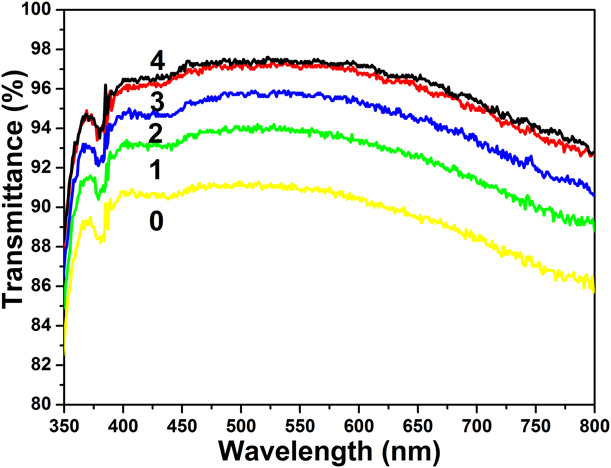
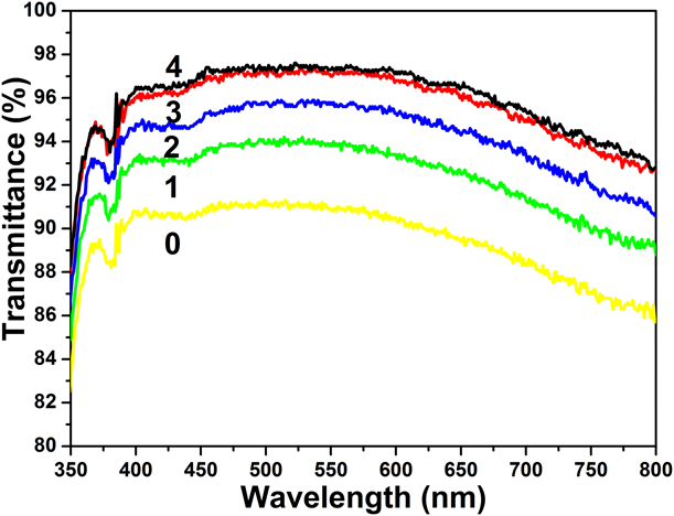
Optical clarity is of great importance for optical and display devices, and it is highly desired in practical applications. Optical coatings can reduce reflection and enhance transmission, and thus have attracted a great deal of interest in industrial and academic fields [Reference Buskens, Burghoorn, Mourad and Vroon8, Reference Yao, He, Geng and Ren12]. The optical performances of the coatings are evaluated by transmittance measurements in the visible region. A good antireflection coating should show an overall high transmittance over the entire visible region, and not at a specific point or within a certain wavelength range. This may impart color to the glass due to visible absorption. The coated nanoporous structure (low refractive index) and coating thickness are believed to affect the transmittance of coatings, through packing of different sizes of ZrO2 and SiO2 NPs; nanopores (n a = 1.00) are introduced to lower the refractive index of the coating. When the refractive index is 1.22, the wavelength of maximum suppression is determined by the quarter-wave optical thickness of the coating. The quarter-wave coating, in turn, can be tuned over the entire visible region by simply controlling the number of bilayer stacks. In order to better understand the relationship between transmittance and the number of bilayer stacks, we prepared a series of coatings that contained 1, 2, 3, and 4 bilayers of ZrO2/SiO2 coatings calcined at 520 °C. Fig. 7 shows the transmission spectra of ZrO2/SiO2 multilayer coatings with different bilayer stacks on a glass substrate in the spectral range between 350 and 800 nm, and a bare glass is used for comparison. With the increase in the number of stacks, the average transmittance values in the visible region (380–780 nm) were increased to approximately 93.3%, 95.2%, 96.7%, and 96.9%, respectively. The transmittance values increased significantly compared with that of the bare glass (90.6%). This may be attributed to the coating thickness and the surface nanoporous structure (low refractive index). When the transmittance increases to 96.7% (three stacks), the coating thickness is near the quarter-wave coating [approximately 140 nm, see Fig. 8(d)], and therefore, there is little increase in transmittance (0.2%) for four stacks. For rapid and high-efficiency preparation, the three stacks were chosen as an optimum condition to study the coating properties.
UV-Vis transmission spectra of ZrO2/SiO2 coatings on glass substrates with 1–4 bilayer stacks calcined at 520 °C, and a bare glass (0) provided for comparison.
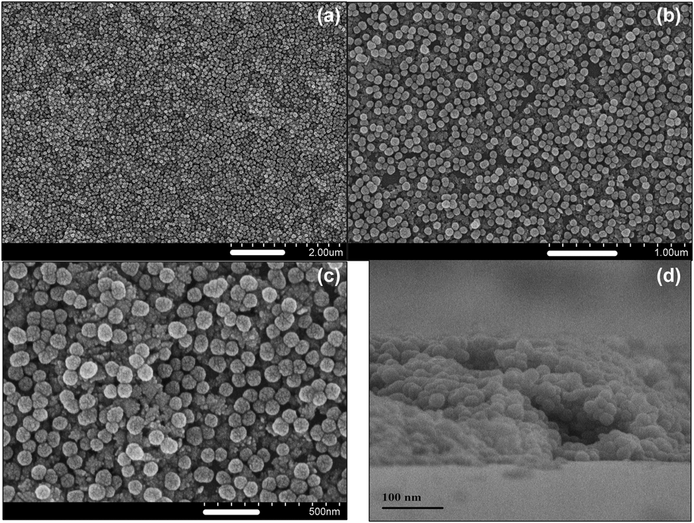
SEM images of spray-spin-blow LbL assembled (a) ZrO2/SiO2 coatings. (b) and (c) are the magnified images of the coatings. (d) Cross-sectional SEM image of the multifunctional AF coatings. The scale bar in (a), (b), (c), and (d) is 1000, 500, 200, and 100 nm, respectively.

Morphology and structure of multifunctional AF coatings
Surface texture (surface roughness and void space) is believed to affect both the transmittance and wetting property of the coating. Using a SSBLbL assembly of different sizes of ZrO2 and SiO2 NPs, a 3D nanoporous network texture is introduced to the surface of the coating. SEM images in Fig. 8 show the surface morphologies and structures of ZrO2/SiO2 coatings. Two kinds of NPs of different sizes can be seen clearly, and their mutual assembly can increase the surface roughness and nanoporosity. Top-view SEM images [Figs. 8(a) and 8(b)] show that the glass substrate was homogeneously covered by ZrO2 and SiO2 NPs; most obviously, the SiO2 NPs, which are of bigger size, are spherical particles of uniform size. The magnified SEM image of the coating [Fig. 8(c)] reveals that the dense pores with sizes between 20 and 50 nm are clearly observed in the coating. The size of the SiO2 NPs is approximately 55 nm in the SEM images [Figs. 8(a)–8(c)], but this is not the real particle size; the true size is approximately 45 nm because the sample surface was covered by gold NPs. In order to reduce charging effects that are caused by high-power electron beams during examinations, the sample was gold-plated using a sputter coater, and the thickness of the gold coating was approximately 10 nm. The three images [Figs. 8(a)–8(c)] were captured from different positions, and the size of the SiO2 NPs is in agreement with the data from the TEM (approximately 45 nm) and Zetasizer Nano-ZS instrument (44.6 nm). From the SEM images, we can see that the ZrO2/SiO2 coatings have a high nano-roughness surface, which has a 3D interconnected nanoporous network structure. It is noted that the coated surface with raspberry-like, mulberry-like, or cauliflower-like particles is not the real surface topography; most of the particles on the surface are Au nanocluster particles. From a cross-sectional SEM image [Fig. 8(d)], it could be seen that the spherical SiO2 NPs were connected to one another and densely packed on the surface. The average thickness of the coatings was approximately 140 nm. It should be noted that the ZrO2 NPs with positive electrical charge in the coating are more attracted to water with negative charge due to electrostatic attractions. Overall, the coating with a nano-roughness surface and an appropriate thickness can exhibit exciting superhydrophilic/AF and antireflection properties.
AF/superhydrophilic performances
The superhydrophilicity of solid surfaces is currently receiving a lot of attention in material science because of its scientific significance and numerous potential applications. According to the early theoretical work by Wenzel [Reference Wenzel29] and Cassie–Baxter [Reference Cassie and Baxter30], and more recent studies by Quéré and coworkers [Reference Bico, Marzolin and Quéré31, Reference Bico, Tordeux and Quéré32], the textured surfaces and void fraction can significantly enhance the wettability of surfaces with water. This may result in enhanced AF properties. As is well known to all scholars working in the field, the superhydrophilic coatings/superhydrophilicity can significantly inhibit fogging by preventing light-scattering water droplets from forming on a substrate surface. In this work, the coating surface was instantaneously and thoroughly wetted by water and thus covered with a thin sheet-like water membrane. The transparent water membrane eventually disappeared either by sliding down under the action of gravity or by evaporation. Thus, the coating surface could effectively maintain optical transparency. The AF/superhydrophilic performances were investigated using a WCA test, a boiling test, and a low-temperature AF test.
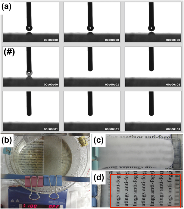
WCAs were carried out at room temperature using a Krüss DSA 30 system, and the average WCA value was obtained by measuring more than five different positions on each sample. The spreading process of the water droplet was recorded by a CCD camera with a frame rate of 25 frames/s. A water droplet of 3 μL was dropped carefully onto the sample; once the water droplet contacted the sample surface, the machine began to take photographs at 25 frames/s (time interval between frames 40 ms). As soon as the first water droplet contacted the ZrO2/SiO2 coating, it spread flat instantaneously to form a thin sheet-like water membrane in less than 0.04 s [Fig. 9(a)]. The water droplet dripping moment [marked “#” in Fig. 9(a)] was captured by the CCD camera. This confirmed that the coating was superhydrophilic. A video of the AF/superhydrophilic behavior is presented in Supplementary material (Movie S1).
(a) Still images captured from video recordings for a water droplet (3 μL) spreading on a substrate covered with multifunctional AF coatings. (b) Photo image of the boiling test. Comparison of the AF behavior of ZrO2/SiO2 coatings (red clip) with a bare glass slide (blue clip). Photo images of a bare glass (c) and the substrate coated with ZrO2/SiO2 coatings (d) after being stored at −15 °C for 3 h in a freezer.

In the boiling test (constant 100 °C), the experiment was carried out using more than five parallel samples to ensure accuracy, and results were obtained. As seen in Fig. 9(b), the coated slide (red clip) always remained visible. The words at the bottom of the beaker remained visible. In sharp contrast, nothing can be seen through the bare glass slide (blue clip). The experiment was maintained constant at 100 °C for 8 h. The results confirmed that ZrO2/SiO2 coatings had excellent AF performance, much more than expected. This was because the nearly instantaneous, sheet-like wetting by water prevented light-scattering water droplets from forming on the substrate surface. It is noted that the ZrO2 NPs carry positive electrical charges, and water carries negative charges. The ZrO2 NPs with positive electrical charge on the bottom are more attracted to the negatively charged water due to electrostatic attractions [Reference Yang, Wang, Yang and Cai3]. This can contribute to improving the hydrophilic effect.
In the low temperature AF test, the samples (more than five parallel samples) were stored in a freezer at −15 °C for 3 h, and then all samples were simultaneously exposed to humid air (approximately 20 °C and 65% relative humidity (RH)). As revealed in Figs. 9(c) and 9(d), the bare glass slide [Fig. 9(c)] covered with heavy frost and the words below are completely invisible due to strong light scattering. In sharp contrast, the substrates coated with ZrO2/SiO2 [Fig. 9(d)] coatings can remain highly transparent and the words below can be seen clearly (red wireframe) because the superhydrophilic surface can prevent the formation of light-scattering tiny ice droplets which are capable of scattering light randomly on a surface. The results of these tests confirmed that the ZrO2/SiO2 coatings with rough surface and nanovoids exhibited exciting superhydrophilic and AF properties.
SC/easy-to-clean performances and mechanical stability
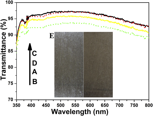
AF and AR coatings, as well as SC/easy-to-clean properties may be of advantage in certain applications. The SC/easy-to-clean effect is obtained when a substrate surface is superhydrophilic (water dissolves contaminants and washes them away more easily) or superhydrophobic (water forms balls and carries away contaminants). It is always associated with long-term stability of the coating, which is an important parameter for evaluating the coating performance. The durability of the SSBLbL electrostatically assembled ZrO2/SiO2 coatings was investigated by an outdoor test over a year, as shown in Figs. 10(a) and 10(b). The vertically placed samples (with dimensions of approximately 12 × 6 cm) were kept in an actual outdoor environment and suffered from wind and weather during the test. The coated and uncoated glass surfaces were captured by a digital camera (IXUS130; Canon, Tokyo, Japan) in Fig. 10(e). However, it was very difficult to take photographs for contaminants on the glass surface which was transparent. We used a light brown rough wall as a background, and positioned a camera at a certain angle to capture the contaminants on the glass surface. As seen in Fig. 10(e), the uncoated glass (left) has much contaminants on the surface, yet there were few contaminants on the coated glass (right). This is because the superhydrophilic surface of the ZrO2/SiO2 coating makes the water spread over the surface completely and instantaneously. At the same time, the coated surface absorbs the water molecules more easily. This combination makes it easier to dissolve the contaminants and wash them away. Figures 10(a) and 10(b) show the transmittance values of the outdoor test: the solid line [Fig. 10(a)] and dotted line [Fig. 10(b)] show the transmittance of the ZrO2/SiO2 sample before and after the outdoor test (investigated for more than a year), respectively. No apparent decrease (less than 1.8%) in transmittance was seen over a year. In the WCA test, the water droplet took a little longer time (∼0.3 s) to completely spread on the coatings left in outdoor service for more than a year. It shows that the multifunctional AF coatings have excellent stability after long-term service.
UV-Vis transmission spectra of the ZrO2/SiO2 sample before (a, solid line) and after (b, dot line) an outdoor test over a year. Comparison of the transmission spectra of the ZrO2/SiO2 sample before (c, solid line) and after (d, dotted line) the abrasion test. (e) Comparison of the contaminants on the glass surface of the ZrO2/SiO2-coated glass (right) and an uncoated glass (left) in an outdoor test over a year.
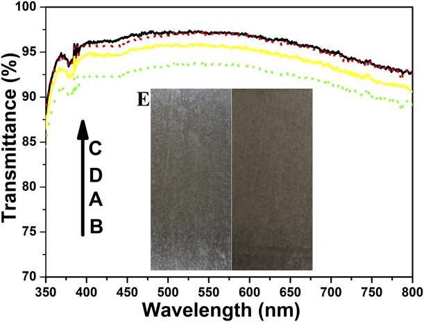
The mechanical stability of the SSBLbL electrostatically assembled ZrO2/SiO2 coating was investigated by a pencil hardness test and a sandpaper abrasion test. In the pencil hardness test, the results confirmed that the ZrO2/SiO2 samples achieved more than 4H pencil hardness (ASTM D3363-05). In the sandpaper abrasion test, the sample was moved back and forth (1 abrasion cycle) under a 100-g load for a constant 10 cm on a sandpaper (grit No. 320). Hundred abrasion cycles were applied to each side. The abrasion resistance was evaluated by comparing the transmittance values before and after the tests, as shown in Figs. 10(c) and 10(d). The solid line [Fig. 10(c)] and dotted line [Fig. 10(d)] show the transmittance of the ZrO2/SiO2 sample before and after the abrasion test, respectively. There is no observable decrease in transmittance in the visible region and the thickness of the coatings still remains unchanged (approximately 140 nm). We also investigated the AF behavior: the ZrO2/SiO2 samples after the abrasion test still had a good AF effect (approximately 0°, <0.04 s). Hence, we have demonstrated a simple coating which exhibits excellent SC/easy-to-clean and AF properties due to the superhydrophilicity of the coating.
Conclusions
In this work, a novel, rapid, and high-efficiency spray-spin-blow LbL assembly technique has been developed for fabricating multifunctional AF coatings/films on glass substrates by three bilayer stacks of alternating positively charged ZrO2 NPs and negatively charged SiO2 NPs. The oppositely charged NPs were bound firmly together via electrostatic interactions. The high-temperature calcination (520 °C) removed organics and impurities from the surface, endowed the coating with enhanced mechanical robustness, and introduced 3D nanoporous networks in the resultant coating along with hydrophilicity improvement. The SSBLbL assembly technique, combined with very tight process control, presented a simple, efficient, and low-cost nanomanufacturing capability to produce coatings/films. The resultant coatings exhibited excellent AF and SC properties due to the superhydrophilicity of the coating, showed excellent AR properties due to a suitable coating thickness and the low refractive index coating formed from the nanoporous morphology (n air = 1.00), and exhibited excellent superhydrophilic properties due to a 3D nanoporous network texture. Meanwhile, we have confirmed that the AF, superhydrophilic, AR, and SC properties, as well as high mechanical stability can be integrated into the same coating consisting of ZrO2 and SiO2 NPs. The simplicity of the fabrication process, easy availability of the nanomaterials, and excellent adhesion to substrates for the coating preparation might make the low-cost, nontoxic, and eco-friendly multifunctional coatings potentially useful in optical and display devices.
Experimental section
Materials
All chemicals in this study were used as purchased; tetraethyl orthosilicate (TEOS; 98+%), aqueous ammonia (NH3, 28%), concentrated sulfuric acid (95–98 wt%), hydrogen peroxide (30%), zirconyl oxychloride (ZrOCl2·8H2O, 99%), and anhydrous ethanol (99.80%) were all obtained from Sinopharm Chemical Reagent Co., Ltd. (Shanghai, China). Ultrapure water was obtained from a three-stage Millipore Mill-Q Plus 185 purification system (Academic, resistivity higher than 18.2 MΩ·cm).
Preparation of monodisperse SiO2 NPs
SiO2 NPs of approximately 45 nm in size were prepared as follows [Reference Yang, Wang, Yang and Cai3, Reference Stöber, Fink and Bohn33]. 100 mL anhydrous ethanol and 3.2 mL aqueous ammonia were mixed with stirring in a round-bottomed flask at room temperature in a water bath, and then 2.1 mL of TEOS was added dropwise to the solution under stirring at 1500 rpm for 15 min. Afterward, the temperature was increased to 30 °C and kept at this temperature under magnetic stirring at 500 rpm for 48 h. Finally, the ethanol suspension of silica NPs of approximately 45 nm size was obtained. The as-prepared SiO2 sol was diluted in ethanol and ultra-sonicated before use. The final concentration of silica was 0.8 mg/mL, and it had a −40.9 mV zeta potential and 44.6 nm size [PDI = 0.047] as measured by a Malvern Zetasizer Nano-ZS instrument.
Preparation of ZrO2 NPs
With reference to previous studies [Reference Yang, Wang, Yang and Cai3, Reference Hu, Harris and Byers34, Reference Kumari, Li, Xu, Leblanc, Wang, Li, Guo and Zhang35], ZrO2 NPs were synthesized using a modified hydrothermal method as follows: 85 mL ZrOCl2·8H2O (0.1 M) and 70 mL anhydrous ethanol were mixed in a beaker by magnetic stirring for 15 min at room temperature. Then the solution was transferred into a Teflon-lined stainless-steel autoclave (200 mL capacity) and heated at 195 °C for 16 h. After the autoclave was cooled down to room temperature naturally, the product was purified by centrifugation and redispersed in ethanol via an ultrasonication-assisted process. The ZrO2 was diluted in ethanol to a final concentration of 0.8 mg/mL. Afterward, the zeta potential was measured using a Zetasizer Nano-ZS instrument, and it had a +43.3-mV zeta potential value.
Fabrication of multifunctional AF coatings
Glass microscope slides (SAIL BRAND Cat. No. 7101) with dimensions of approximately 25.4 × 76.2 × 1 mm were immersed in a slightly boiled piranha solution (70/30 v/v of 98 wt% H2SO4/30 wt% H2O2; caution: piranha solution reacts violently with organic compounds and should not be stored in closed containers) for 6 h, then rinsed with ultrapure water and ethanol, and then blown dry under nitrogen. The cleaned glass slides were obtained and used as substrates in the following experiments. Multifunctional coatings were fabricated using a SSBLbL assembly process, and this process is driven by electrostatic interactions between the positively charged ZrO2 NPs (+43.3 mV) and negatively charged SiO2 NPs (−40.9 mV). As seen in Fig. 5, a glass substrate was held on a vacuum chuck and spun at 1500 rpm throughout all steps of the spray-spin-blow process to ensure even coverage. The spray nozzle diameter was 0.3 mm, and the distance between the substrate and the nozzle was fixed to 15 cm; the positively charged ZrO2 nanosol (+43.3 mV) and negatively charged SiO2 nanosol (−40.9 mV) were alternately sprayed on the substrate. Between each layer deposition, the film was blown dry with hot air for 10 s to ensure complete drying. The spray time was 1.5 s for both ZrO2 nanosol and SiO2 nanosol with a spray pressure of 10 psi (69 kPa). A typical bilayer was assembled as follows. The substrate was spun constantly at 1500 rpm throughout all four steps to ensure the formation of an evenly thin film. The positively charged ZrO2 nanosol was sprayed for 1.5 s to render the substrate surface to be charged. Next, the film was blown dry with hot air for 10 s while spinning. Then, the negatively charged SiO2 nanosol (−40.9 mV) was also sprayed for 1.5 s, followed by drying for another 10 s. In this way, one positively charged ZrO2 inner layer and one negatively charged SiO2 outer layer were fabricated due to electrostatic interactions. If desired, a washing step can be incorporated before the drying step. This process completed one cycle of SSBLbL assembly to form a single bilayer of ZrO2 NPs and SiO2 NPs. The same process was then repeated until the desired number of bilayers was achieved. The other side of the glass substrate was treated in the same way as above. Finally, the as-prepared coatings were calcined (heating rate: 2 °C/min) in a muffle furnace for 2.5 h to remove organics and improve their adhesion to the substrate. They were then subsequently cooled down to room temperature with a cooling rate of 3 °C/min.
Characterization methods for multifunctional AF coatings
The morphology and size of SiO2 and ZrO2 NPs were observed using a transmission electron microscope (TEM; JEM-2100, JEOL, Tokyo, Japan) with an acceleration voltage of 200 kV equipped with a Gatan CCD camera. Surface morphology and cross section of the coatings were investigated using a field-emission scanning electron microscope (FE-SEM; Hitachi S-4800, Tokyo, Japan) operated at an acceleration voltage of 5 kV. Prior to imaging, the samples were sputtered with gold to reduce charging effects during examinations. The zeta potential and particle size were measured in triplicate using a Zetasizer Nano-ZS (Malvern instruments, Malvern, U.K.) at a temperature of 25 °C. The X-ray powder diffraction (XRD) data were collected at room temperature using a D/Max-2550 PC diffractometer (Rigaku, Japan) equipped with an X-ray tube (Cu Kα radiation: λ = 1.5406 Å; 40 kV, 200 mA) to identify the crystalline phases of the samples. Transmission spectra in the range between 350 and 800 nm were performed using a U-3310 UV-Vis spectrophotometer (Hitachi Co., Ltd., Japan) at a RH of approximately 30%. WCAs of surfaces were measured at an ambient temperature using a Krüss DSA 30 drop shape analysis system (Krüss GmbH, Hamburg, Germany), and a water droplet (>18.2 MΩ cm) of 3 μL was dropped carefully onto the sample surface and also used as the indicator to characterize the wetting property of the coating. The spreading process of the water droplet was recorded by a CCD camera at a capture speed of 25 frames/s. AF properties were evaluated by two methods. One was a boiling test [Reference Yang, Wang, Yang and Cai3], in which the samples were placed on the top of a beaker containing boiling water (80% full), and vapor condensed on the coating surface was observed and photographed. The other was a low temperature AF test, in which the samples were stored in a freezer at −15 °C for 3 h and then exposed to humid air (at 20 ± 3 °C and 65 ± 5% RH) simultaneously to observe whether fog was formed on the coating. An electric furnace (HMX1100-20, Shanghai Haoyue Electric Technology Co., Ltd., Shanghai, China) was used to calcinate the coatings. A digital camera (IXUS130; Canon, Tokyo, Japan) was used to capture the images.
Supplementary material
To view supplementary material for this article, please visit https://doi.org/10.1557/jmr.2019.309.
Acknowledgments
This work was supported partially by the Key Research and Development Plan Project of Anhui Province (Grant No. 1804a09020077).