I. INTRODUCTION
Metal matrix nanocomposites (MMNCs) are developed from metal matrix composites (MMCs), the main characteristic of which is that at least one of phases shows dimensions in the nanometer range (1 nm = 10−9 m). Obviously, there are a large number of interfaces between the matrix and reinforcements by the addition of nanoparticles in MMNCs, which gives a rise to a large improvement in interactions at phase interfaces, thus enhancing material properties. By comparison to the conventional MMCs, MMNCs can introduce superior mechanical properties and more attractive physical functions, such as electric, magnetic, and optical properties. Reference Camargo, Satyanarayana and Wypych1,Reference Sekino and Niihara2 However, it is acknowledged that nanoscale reinforcements, owing to large surface energy, are much prone to form agglomerations under the action of strong van der Waals' force, which is harmful for their homogeneous distribution throughout metal matrix, thus deteriorating subsequent mechanical properties. Reference Seal, Kuiry, Georgieva and Agarwal3 In an effort to achieve desirable mechanical properties, some technologies need to be introduced, a simple and effective one of which is mechanical alloying (MA).
MA, as a low temperature, nonequilibrium and solid state processing technique, has been demonstrated as an efficient method to avoid agglomeration of nanoparticles and improve the distribution of nanoparticles throughout metal matrix. Reference Zhang4–Reference Marta, Jan and Jerzy6 During MA processing, powder particles undergo a series of evolutions of morphology, size, and microstructure by means of repeated deformation/welding/fracture mechanisms. These evolutions involve mass transfer between different components, therefore accelerating the homogeneously distributing process. Reference Enayati and Mohamed7 The nanocomposites with different matrixes have been successfully synthesized through MA. For instance, Zhou et al. successfully achieved the nanostructured Cu–5 wt%Al2O3 nanocomposites powder by high-energy mechanical milling and simultaneously studied the grain growth of nanocrystalline Cu matrix during annealing. It had been found that the microstructure of the nanocrystalline Cu matrix exhibits a good thermal stability, due to the dramatic drag effects of finely distributed Al2O3 nanoparticles and Al3+/O2− clusters on the grain boundary motion. Reference Zhou, Zhang, Kong, Munroe and Torrens8 El-Eskandarany used high-energy ball milling to achieve SiC reinforced Al-based nanocomposites. It was further found that the increasing volume fractions of the SiC reinforcement led to an increase of the density, hardness, and elasticity modulus of the composite samples. Reference El-Eskandarany9 Also, the nanocomposites reinforced with nanometer-sized TiC dispersed uniformly throughout the W matrix were produced by Zhang and Gu through MA and the amorphization of W constitute gradually occurred with the milling time increasing. Reference Zhang and Gu10
Another crucial procedure is the consolidation after successful preparation of appropriate powders. Within the last years, selective laser melting (SLM), as a promising manufacturing technology, relatively prevails in the all world, which enables to produce near fully dense objects via full melting mechanism and avoids the lengthy post processing cycles in the conventional powder metallurgy. Reference Kruth, Mercelis, Vaerenbergh, Froyen and Rombouts11,Reference Attar, Bönisch, Calin, Zhang, Zhuravleva, Funk, Scudino, Yang and Eckert12 During SLM processing, three-dimensional (3D) parts with any complex shapes can be built rapidly by selective melting and subsequent rapid solidification of the deposited powder layers with the laser beam scanning. The information of each layer derives from the precreated 3D model in the computer. Reference Gu, Meiners, Wissenbach and Poprawe13,Reference Olakanmi, Cochrane and Dalgarno14 Due to the above mentioned characteristics, SLM has a particular nonequilibrium physical and chemical metallurgical nature, thereby producing the novel microstructures and excellent performance of the manufactured components. Reference Vrancken, Thijs, Kruth and Humbeeck15
An increasing emphasis has been placed on the design and preparation of aluminum matrix nanocomposites (AMNCs), due to a rapid increase of the demand of light-weight and high performance materials in the aerospace and automotive industries. Reference Wang and Gu16 AMNCs with different types of reinforcements, such as TiB2, SiC, B4C, and carbon nanotubes, have been successfully synthesized. Reference Li, Chen, Wang, Lavernia and Shan17–Reference Poirier, Gauvin and Drew20 To further improve the properties of AMNCs, hybrid AMNCs reinforced by different ceramic nanoparticles also have been developed by the conventional methods such as powder metallurgy. Reference Mohammad Sharifi and Karimzadeh21 However, few research work has been performed on the microstructural evolution of hybrid AMNCs powder during MA processing, which is important for the preparation of desirable hybrid AMNCs powder suitable for SLM processing.
In this study, aluminum-based nanocomposites powder with hybrid reinforcements was synthesized by MA of the original TiN and AlSi10Mg powder mixture, and subsequently consolidated by SLM. The evolution of microstructure and particle morphology of the milled powders was analyzed in detail. The interaction between reinforcement components and the matrix as well as the reasonable forming mechanism of Aluminum-based nanocomposites powder with hybrid reinforcements was also presented. In addition, the microstructures and mechanical properties (hardness, tribological property) of the SLM-processed part were assessed.
II. EXPERIMENTAL PROCEDURE
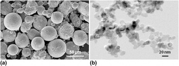
Figure 1 shows the morphologies of the raw materials used in this study including: AlSi10Mg powder with a mean particle size of 30 µm and a spherical morphology, as well as TiN powder with a mean particle size of 15 nm and an irregular shape. By weighting and a simple mechanical mixing, powder mixtures containing 19 g AlSi10Mg and 1 g TiN were prepared. The MA processing was performed in a high-energy Pulverisette 6 planetary mono-mill (Fritsch GmbH, Idar-Oberstein, Germany). In this experiment, as-weighted powder mixtures were placed into a hardened chromium steel grinding bowl, together with stainless steel grinding balls (20 Ø20 mm balls, 20 Ø14 mm balls, 80 Ø10 mm balls, and 100 Ø6 mm balls). The ball to powder weight ratio was 10:1. Then different milling times 2, 5, 10, 15, 20, and 30 h were set, while the rotation speed of the supporting disc was fixed at 250 r/min. Finally, to avert excessive temperature accumulation during ball milling, 15-min ball milling duration was followed by an interval of 10 min. Subsequently, the 2 kg of 20-h ball milled nanocomposite powder was prepared for the consolidation by SLM. The SLM system consisted of a YLR-200-SM ytterbium fiber laser with a power of ∼200 W and a spot size of 70 μm (IPG Laser GmbH, Burbach, Germany), an automatic powder spreading device, an inert argon gas protection system, and a computer system for process control. As the specimens were to be built, an aluminum substrate was fixed on the building platform (174.50 mm × 174.50 mm × 14.50 mm) and leveled. Then, the building chamber was sealed and the argon gas with an outlet pressure of 30 mbars was fed inside to decrease the O2 content below 20 ppm. Afterward, the milled powder was deposited on the substrate by the powder spreading device. The laser beam was then controlled by computer-aided design (CAD) model to scan the spread powder selectively, forming a two-dimensional profile. By the parameter optimization, the following suitable processing parameters were chosen: the laser powder of 200 W, the scan speed of 200 mm/s, and the powder layer thickness of 50 μm were settled. A simple linear raster scan pattern was used, with a scan vector length of 4 mm and a hatch spacing of 100 μm.
Morphology of initial powder particles. (a) SEM image of AlSi10Mg powder; (b) TEM micrograph of TiN powder.

The phases of the milled powders were identified by a Bruker D8 Advance x-ray diffractometer (XRD; Bruker AXS GmbH, Karlsruhe, Germany) with Cu Kα radiation (λ = 0.15418 nm) at 40 kV and 40 mA using a continuous scan mode. A quick scan at 4°/min was primarily performed within a wide range of 2θ = 20–90° to give a general exhibition of diffraction peaks. A slower scan rate of 1°/min was further used over 2θ = 38–39° to give a more accurate determination of peaks. The average crystallite size of the milled powder was determined based on XRD peak broadening using the Williamson–Hall formula Reference Suryanarayana22 :
 $$B\,{\rm{cos}}\,\theta = {{0.9\lambda } \over {{D_{\rm{C}}}}} + \varepsilon \,{\rm{sin}}\,\theta \quad ,$$
where B is the full width at half maximum of the XRD peak, θ is the diffraction angle, λ is the wave length of x-ray, D C is the average grain size, and ε is the microstrain. Specimen for metallographic examinations was prepared according to the standard procedures and etched with a solution composing HF (2 mL), HCl (3 mL), HNO3 (5 mL), and distilled water (190 mL) for 10 s. A PMG3 optical microscope (Olympus Corporation, Tokyo, Japan) was used to observe the low-magnification microstructures of MA-processed powder specimen and SLM-processed specimen. High-resolution study of the microstructural features of the powders and SLM-processed part were characterized using an S-4800 field emission scanning electron microscope (FE-SEM) (Hitachi, Tokyo, Japan) at an accelerating voltage of 5.0 kV. Chemical compositions were determined by an EDAX energy dispersive x-ray spectroscope (EDX) (EDAX, Inc., Mahwah, NJ). The interior nanostructures obtained in as-milled powders were studied using a JEM-2100 (HR) transmission electron microscopy (TEM) (JEOL Company, Tokyo, Japan). For the SLM-processed part, the portable SJ-201P surface roughness tester (Mitutoyo Company, Kawasaki, Japan) was used to assess the surface roughness of the part. Besides, the Vickers hardness was measured using a MicroMet 5101 microhardness tester (Buehler GmbH, Braunschweig, Germany) at a load of 0.1 kg and an indentation time of 15 s. The tribological property of the specimen was estimated by the dry sliding wear tests conducted in a HT-500 ball-on-disk tribometer (Lanzhou ZhongKe KaiHua Sci. &Technol. Co., Ltd., Lanzhou, China) in air at room temperature. The counter material was GCr15 bearing steel ball with a diameter of 3 mm and a mean hardness of HRC 60, and a test load of 230 g was applied. The friction unit was rotated at a speed of 560 r/min for 15 min, with the rotation radius of 2 mm. The coefficient of friction (COF) of the specimens was recorded during wear tests.
III. RESULTS AND DISCUSSION
A. Phase determination and crystallite size
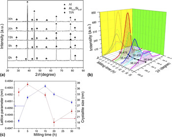
Figure 2 depicts the XRD patterns obtained over a wide range of 2θ (20–90°) and a thin range of 2θ (38–39°) with the milling time increasing. The strong diffraction peaks corresponding to Al and Al3.21Si0.47 were clearly detected and the TiN peaks seemed relatively weak due to small weight fraction and nanoscale size [Fig. 2(a)]. The intensity of main diffraction peaks became weak with milling time increasing, which might indicate that crystal lattices were distorted because of the position changes of atoms. In addition, Al diffraction peaks also broadened and simultaneously shifted to lower angles generally as the milling time prolonged from 0 to 15 h [Fig. 2(b)]. However, a further increase in the milling time to 30 h gave rise to the situation that the Al peaks shifted to higher angles.
(a) XRD patterns obtained over a wide range of 2θ (20–90°) showing different diffraction peaks of as-milled powders in the different milling times 0, 5, 15, 20, and 30 h. (b) 3-D image showing diffraction peaks change of Al in a thin range of 2θ (38–39°) with the milling time increasing; (c) change of lattice parameter and crystallite size of Al matrix with the milling time.

The changes of the lattice parameter and crystallite size of α-Al phase with the milling time are revealed in Fig. 2(c). For the beginning powder, the lattice parameter of α-Al phase was 0.404813 nm, which was smaller than that of pure Al phase without any crystal defects. In the view of the condition that the original powders were produced by rapid solidification technical, a certain quantity of silicon was dissolved into Al matrix, explaining the result of the decreasing lattice parameter. Reference Yamauchi, Takahara, Tanaka and Matsubara23–Reference Dong, He and Mi25 A solid solubility of Si in Al matrix can be estimated as about 0.557 at.% by using the linear relationship between the lattice parameter and the atomic fraction of Si given by Bendjik et al. Reference Bendijk, Delhez, Katgerman, De Keijser, Mittemeijer and Van Der Pers26 With the milling time increasing to 15 h, the lattice parameter of Al phase reached the maximum 0.405326 nm. After that, the lattice parameter of Al phase decreased significantly to 0.405086 nm when the milling time reached 30 h. Wang and Gu pointed out that the lattice distortion was mainly attributed to the solid solution of Mg and Si atoms into the Al matrix. Reference Wang and Gu16 Considering the Hume-Rothery rule Reference Mittemeijer27 that the solubility is significantly influenced by the atom size factor, it is believed that nearly full Mg atoms diffuse into Al base when the milling time increases from 0 to 15 h. As the milling time further increases to 30 h, the lattice distortion degree of α-Al phase tends to decrease, due to significant refinement of crystalline size as well as the solid solution of Si in Al, which had been observed in some researches. Reference Suryanarayana22,Reference Clark, Suryanarayana and Froes28
With regarding to the variation of crystallite size of α-Al phase, the crystallite size increased from 34.18 nm to 38.33 nm during 0–5 h milling [Fig. 2(c)]. After 20 h of milling, the crystallite size decreased sharply to 18.23 nm and slightly increased when the powder was milled for 30 h. The grain subdivision into the subgrains has been found to be the main mechanism responsible for significant grain refinement. Reference Wu, Tao, Hong, Xu, Lu and Lu29–Reference Wen, Liu, Gu, Guan and Lu31 At the early stage of ball milling, powder mixtures have a good capacity of bearing a mass of plastic deformation. The deformation in turn leads to the formation of high density of crystal defects such as dislocations and point defects lying in powder particles, driving the lattice strain to get enhanced. Dislocations interact with each other to form dense dislocation walls (DDWs) and dislocation tangles (DTs). As the milling time extending, these DDWs and DTs transform into subboundaries with small misorientations to separate individual cells or subgrains. When more and more dislocations move into the subboundaries, the misorientation increases continuously and finally the subboundaries evolve into the high-angle boundary, which means that grain refinement has occurred.
B. Particle morphology evolution of MA-processed powders
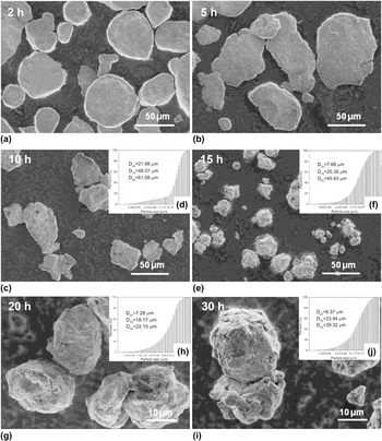
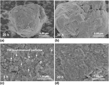
Figure 3 describes the morphology evolution and particle size distribution of the powder milled for 2, 5, 10, 15, 20, and 30 h. Furthermore, to achieve a better understanding of the surface morphology of as-milled powders as well as the distribution state of reinforcement particles throughout the Al matrix, FE-SEM characterization at a higher magnification is performed, as shown in Fig. 4. After 2 or 5 h of milling, the plate-like powder particles with a mean size of about 40–50 μm [Figs. 3(a) and 3(b)] were observed, which indicated that the powder particles suffered severe plastic deformation in this stage and consequently the cold-welding mechanism predominated the milling procedure. Additionally, traces of cold-welding could be easily seen on the surface of powder particles and these traces gradually became unconspicuous with the milling time increasing. The high-magnification FE-SEM observation revealed that the flattened powder particles had a relative rough or shaggy surface which interspersed by many fine fractured TiN reinforcement particles [Fig. 4(c)]. With the milling time increasing to 10 h, particle morphology changed to the irregular shape and the mean particle size decreased to 34.64 μm, indicating that the fracture effect had began to prevail over the cold-welding effect [Figs. 3(c) and 3(d)]. After 15 h of milling, the flattened powder particles were violently broken into smaller ones with a mean particle size of 18.67 μm and the particle morphology changed to near-spherical shape [Figs. 3(e) and 3(f)]. When the milling time reached 20 h, the equiaxed particle morphology became more apparent and the particle size distribution was the narrowest (D 25 = 7.28 μm, D 75 = 18.17 μm, D 90 = 22.15 μm) [Figs. 3(g) and 3(h)]. Also, barely free reinforcement particles could be found on the surface of powder [Fig. 4(d)]. Meanwhile, it is clearly seen from Fig. 4(d) that a relative smooth or compact surface structure was obtained successfully after the continuous ball-powder collisions. Hence, it was reasonable to believe that a balance between the fracture effect and the cold-welding effect had reached after 20 h of milling and simultaneously the hard-brittle reinforcement particles had been embedded into Al matrix completely after long-time ball milling (20 h). As the milling time prolonged to 30 h, particle size slightly coarsened and particle morphology also maintained unchanged [Figs. 3(i) and 4(b)]. It should be noted that the step morphology could be clearly seen from powder particles milled for 30 h while there were not apparent steps found in the surface of particles milled for 20 h [Figs. 4(a) and 4(b)], which indicated that atomic diffusion effect among powder particles enhanced and cold-welding mechanism started to dominant again at the end stage of MA.
FE-SEM images showing the morphology features of as-milled powder particles at various milling times: (a) 2 h, (b) 5 h, (c) 10 h, (e) 15 h, (g) 20 h, and (i) 30 h; (d), (f), (h), and (j) showing the particle size distributions corresponding to the milling time 10, 15, 20, and 30 h, respectively.

(a and b) FE-SEM images showing detailed surface microstructure of powders milled for 20 and 30 h, respectively; (c) and (d) FE-SEM images showing distribution state of TiN particles on the surface of powders after 5 and 20 h of milling, respectively.

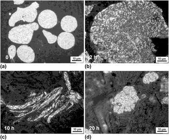
The optical metallographic images of powder particles etched corresponding to the milling time of 0, 2, 10, and 20 h are demonstrated in Fig. 5, further depicting the influence of milling time on the morphology of the powder particles. The unmilled powder particle showed a spherical morphology with a mean particle size of 20–30 μm [Fig. 5(a)]. After 2 h of milling [Fig. 5(b)], the powder particle size significantly increased in comparison with that of unmilled powder particles, which was consistent with the changes observed by FE-SEM [Figs. 3(a) and 3(b)]. After 10 h of milling [Fig. 5(c)], a long strip structure formed through a piling up of plate-like particles was obtained and the interfacial boundaries between adjacent particles were visible, which was also observed by Fogagnolo. Reference Fogagnolo, Velasco, Robert and Torralba32 When the milling time prolonged to 20 h, powder particle size significantly decreased as well as the above mentioned interfacial boundaries were invisible and the equiaxed particle morphology was obtained [Fig. 5(d)].
OM micrographs showing morphologies of as-milled powder particles after (a) 0 h, (b) 2 h, (c) 10 h, and (d) 20 h of milling, indicating the deformation mechanism of powder particles.

C. Morphology evolution and distribution state of hybrid reinforcement particles
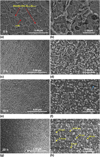
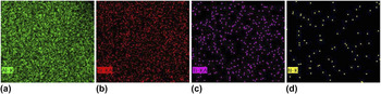
Figure 6 reveals the wispy microstructures of powder particles milled for 0, 2, 10, and 20 h with the help of high-magnification FE-SEM. For the original AlSi10Mg powder particle, a typical microstructure of needle-like Al3.21Si0.47 particles distributed along grain boundaries of α-Al phase could be clearly observed in Fig. 6(a). However, it was found that α-Al grain boundaries consist of Al3.21Si0.47 particles were no longer visible after 2 h of milling [Figs. 6(c), 6(e), and 6(g)]. Also, the original needle-like Al3.21Si0.47 particles [Fig. 6(a)] were found to get pronounced refinement to form granulated morphology, as shown in Figs. 6(c)–6(h). When being further observed, the distribution state of reinforcement particles showed local heterogeneity after 10 h of milling [Fig. 6(e)]. The local heterogeneity weakened or disappeared as the milling time prolonged to 20 h [Fig. 6(g)]. Higher-magnification FE-SEM micrographs of the microstructure of local zones in Figs. 6(a), 6(c), 6(e), and 6(g) are shown in Figs. 6(b), 6(d), 6(f), and 6(h), respectively. The original coarse Al3.21Si0.47 particles were broken into pieces easily during very short milling time, due to that Al3.21Si0.47 belonged brittle phase. An incompletely-broken particle was found in Fig. 6(f) (as pointed by the arrow), reflecting the fragmentation processing of brittle reinforcement particles under the fierce ball-powder collisions. Seen from Figs. 6(d) and 6(f) that partial reinforcement particles demonstrated the polygonal morphology, and the mean size of which was about 0.1 μm and decreased with the milling time extending. After 20 h of milling [Fig. 6(h)], the morphology of the reinforcement particles changed into near-spherical shape and the difference of particle size tended to increase that the minimum size of the reinforcement particle reached dozens of nanometers while the maximum size of the reinforcement particle was 0.3 μm. Figure 7 shows the EDX element mapping of Fig. 6(h), corresponding to the distributions of Al, Si, Ti, and N elements after 20 h of milling. This EDX element mapping basically indicated the homogenous distribution state of the reinforcement throughout the Al matrix.
(a and b) FE-SEM micrographs showing the microstructural features of the original AlSi10Mg powder particle at different magnifications; (c), (e), and (g) FE-SEM micrographs showing the morphology and distribution state of hybrid reinforcement particles within the milled powders after 2, 10, and 20 h of milling, respectively; (d), (f), and (h) high-magnification FE-SEM micrographs of local zone of (c), (e), and (g), respectively.

EDX element mapping of the whole zone in Fig. 5(f) showing distributions of (a) Al, (b) Si, (c) Ti, and (d) N elements after 20 h of milling.

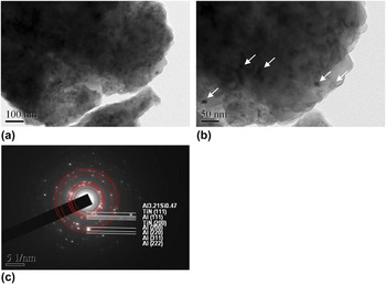
TEM and the corresponding selected area diffraction pattern (SADP) were performed to further observe the morphology and distribution state of reinforcement particles within the matrix, as shown in Fig. 8. Some nanometer-sized reinforcement particles with an average size of about 20 nm and granulous shape were clearly observed to distribute uniformly throughout the matrix [Figs. 8(a) and 8(b)]. Besides, the crystallite morphology of Al matrix was also observed from the edge of TEM images [Fig. 8(a)], the size of which was approximately 30 nm, consistent with the calculated result according to XRD datum [Fig. 2(a)]. Although the rings in the SADP [Fig. 8(c)] were broken, the corresponding Al3.21Si0.47 and TiN phases were still able to be identified. Until now, it should be reasonable to believe that Aluminum-based nanocomposites powder with hybrid reinforcements was successfully prepared by MA after 20 h of milling, owing to the uniform distribution of nanometer/submicrometer-sized TiN and Al3.21Si0.47 particles in the Al matrix as well as the formation of nanocrystalline α-Al matrix.
(a and b) TEM micrograph showing internal nanostructure of powder particle milled for 20 h; (c) the corresponding SADP of powder particle milled for 20 h.

D. Forming mechanism of aluminum-based nanocomposites powder with hybrid reinforcements prepared by MA
It has been widely accepted that MA can improve the distribution of reinforcement nanoparticles, but the explicit explains are still absent. Combined with this study, some rational reasons are present to elucidate this widely accepted fact. (i) Centrifugal effect and impact force from the high-energy ball milling. As-applied rotational speed of the ball mill reached 250 r/min, centrifugal effect was strong enough to make reinforcement particles uniformly dispersed into powder mixtures. Besides, grinding balls with high kinetic energy vehemently collided with powder particles, inducing large enough impact force to break particle agglomerations. (ii) The cut mechanism of dislocation and repeated deformation behavior. In the view of the fact that nanoscale reinforcement particles tended to agglomerate, part reinforcement particles might be embedded into Al matrix by strong ball milling in the form of agglomerations. The agglomerations demonstrated a comparatively loose structure, due to the reason that adjacent reinforcement particles were bonded together solely by van der Waals' force. When a number of dislocations were produced by constant plastic deformations, these loose structures were broken into smaller tight ones as the dislocations moving. Such process was repeated until the force induced by ball-powder collision could not drive dislocations across the powder, which efficiently alleviated the agglomeration of reinforcement particles. (iii) Fragmentation effect. Orowan bowing mechanism Reference Suryanarayana22 played a main role in the movement of dislocations after the size of reinforcement agglomeration decreased to a certain degree. The hard ceramic reinforcement phase significantly hindered the movement of dislocations and accelerated the formation of dislocation rings. As a result, stress concentration occurred in the surrounding areas of reinforcement particles. Subsequently, the accumulated strain energy led to the crack initiation and extension as well as particle fracture, thus improving homogeneous distribution of reinforcement particles.
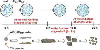
The schematic illustration is present in Fig. 9 to depict the influence of MA on the microstructure of the original AlSi10Mg powder particle and the forming process of Al matrix nanocomposites powder. For the starting powder, the microstructure of AlSi10Mg powder particle consists of dendritic shaped α-Al and coarse need-like Al3.21Si0.47 precipitation along the boundaries of α-Al phase. With ball milling energy applied to the powder mixtures increasing, dendritic shaped α-Al gets deformed and broken, and simultaneously a number of substructures evolved from DTs form in the α-Al phase, therefore leading to a continuous refinement. While coarse Al3.21Si0.47 particles occur to crack directly during very short milling time and get significant refinement, due to the fact that Al3.21Si0.47 belongs to brittle phase. After a long-time milling (20 h), a homogenous microstructure composed of nanometer/submicrometer-sized spherical Al3.21Si0.47 particles embedded into the fine α-Al matrix can be achieved.
A schematic diagram depicting the influence of MA on the microstructure of the original AlSi10Mg powder particle and the forming process of Al matrix nanocomposites powder.

In the terms of the forming process of Al matrix nanocomposites, the original TiN/AlSi10Mg powder system as investigated falls in the typical brittle-ductile component combination. At the early stage of MA (0–5 h), AlSi10Mg undergoes plastic deformation to present a plate-like morphology while TiN undergoes fragmentation to show a fine granulous shape by the ball-powder collision. The violent milling effect induces the production of high density of crystal defects and instantaneous temperature rise, which accelerates the diffusion of atoms in the adjacent particles. As a consequence, cold-welding mechanism predominates in this process and simultaneously laminar structures are formed by piling up flattened powder particles. Besides, nanometer-sized TiN particles firstly attach to the surface of the matrix powder and subsequently are wrapped in the Al matrix. However, work hardening coefficient of powder system dramatically increases due to the addition of hard brittle particles. Under the constant action of ball milling, powder particles start to get severe work hardened and consequently the accumulated strain energy cannot get released in time, thus promoting the initiation of cracks. With the ball milling continued, the cracks develop and finally powder particles undergo fragmentation. Then powder particles demonstrate the near-equiaxial morphology, which implies that fracture mechanism has advantage over cold-welding mechanism in this stage (5–15 h). At the end stage of MA (15–20 h), cold-welding and fracture mechanisms finally reach equilibrium to show a steady state, as a result of which the particle size attains the minimum and the interfacial boundaries are no longer visible by optical microscopy.
E. Characterization of SLM fabricated component
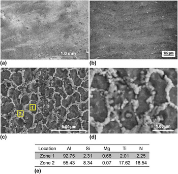
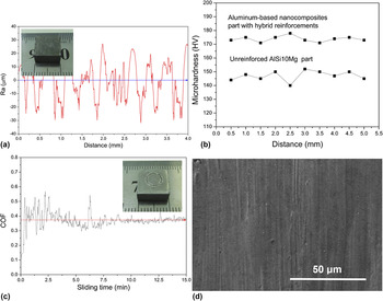
Figures 10(a) and 10(b) illustrate the typical microstructures on the untreated top surface and etched cross section of SLM-processed part. Meanwhile, high-magnification FE-SEM is also performed to show the distribution state and growth tendency of TiN and Al3.21Si0.47 particles throughout the matrix after SLM processing, as shown in Figs. 10(c) and 10(d). The top surface of SLM-processed part was smooth and near fully dense, showing no apparent pores or cracks [Fig. 10(a)]. The density of the part measured by Archimedes principle reached 99.3% theoretical density (TD). Additionally, the surface roughness of the part was also assessed, reaching a relatively low level of 14.5318 μm, as shown in Fig. 11(a). Furthermore, a uniform layerwise microstructural feature was clearly observed by the optical microscope, due to the layer-by-layer incremental deposition manner of the SLM process [Fig. 10(b)]. What is noteworthy is that the microstructure of the part involving α-Al phase and novel circular-structured hybrid reinforcement phase along the boundaries of α-Al phase was observed, which was similar as that of original AlSi10Mg powder [Figs. 10(c) and 10(d)]. The EDX result of the marked zones in Fig. 10(c) indicates that the precipitations along the boundaries of the matrix phase were the mixtures of TiN and Al3.21Si0.47 particles [Fig. 10(e)]. It was further found that the hybrid reinforcement particles bonded with each other to form a continuous circular structure and particle size of the hybrid reinforcement phase in SLM-processed part remained submicrometer scale, showing a slight growth tendency comparing with that of hybrid reinforcement phases in the 20-h milled powder. Besides, hybrid reinforcement particles showed a more rounded morphology after SLM processing.
(a and b) the typical microstructures on the untreated top surface and etched cross section of SLM-processed part; (c and d) high-magnification FE-SEM showing the distribution state and growth tendency of TiN and Al3.21Si0.47 hybrid reinforcement particles throughout the matrix powder; (e) the EDX of zone 1 and 2 in Fig. 10(c), showing the relative atom ratio of different elements.

(a) The surface roughness assessment of the SLM-processed nanocomposites part; (b) the microhardness of the SLM-processed nanocomposites part and unreinforced SLM-processed part; (c and d) the COF and worn surface morphology of the SLM-processed nanocomposites part.

During the SLM processing, the laser induced cooling rate reaches as high as 103–107 K/s, which can inhibit effectively significant growth of nanometer/submicrometer-sized hybrid reinforcement particles. Reference Sun, Zheng, Liu, Liu and Zhang33 On the other hand, the surface tension gradient is developed between the center and edge of the molten pool due to the steep temperature gradient during the high-energy density process. Consequently, a Marangoni convention Reference Kruth, Levy, Klocke and Childs34 is induced by the surface tension gradient within the molten pool, which facilitates the rearrangement of hybrid reinforcement particles and finally leads to the uniform distribution of hybrid reinforcement particles throughout the matrix. When the sufficient laser energy is applied to the powder, TiN particles maintain solid state while Al3.21Si0.47 particles undergo full melting. Then, TiN particles are continuously driven in the molten pool by the torque induced by the misalignment of TiN particle center and get together around the center of Marangoni flow. Besides, a sufficient amount of Al melts form due to the sufficient laser energy, leading to an increase of repulsion forces between TiN particles. The combined effects of repulsion forces and Marangoni flow give a rise to the formation of the circular structure. Reference Gu35 Furthermore, the existence of TiN particles promotes the nucleation of Al3.21Si0.47 crystallites surrounding the TiN particles. Finally, a uniform microstructure consisting of circularly dispersed and nanometer/submicrometer-sized hybrid reinforcement particles embedded in α-Al matrix is obtained.
The microhardness and tribological property of the SLM-processed aluminum-based nanocomposites part are depicted in Figs. 11(b)–11(d). As a reference, the microhardness of the SLM-processed unreinforced AlSi10Mg part is also shown [Figs. 11(b)]. Reference Buchbinder, Schleifenbaum, Heidrich, Meiners and Bultmann36 The Vickers hardness of the SLM-processed aluminum-based nanocomposites part reached a level as high as 178 HV0.1, which was obviously much higher than that of unreinforced AlSi10Mg part, which indicated that the existence of TiN and Al3.21Si0.47 hybrid reinforcements effectively restrained the local microdeformation in the matrix by hindering the movement of dislocations. Besides, fluctuation of the measured Vickers hardness for the nanocomposites part was mild, showing a homogenous distribution state of TiN and Al3.21Si0.47 particles in the matrix. Figure 11(c) shows the change of COF of the SLM-processed aluminum-based nanocomposites part with the sliding time and the sample geometry for the COF sample. At the initial stage of the wear test, COF of the part demonstrated considerable fluctuation and the maximum COF reached 0.569, owing to the existence of thin hard oxide film on the surface of the part. After 8–9 min of the wear test, COF value of the part tended to reach a steady state with little local fluctuation in a range of 0.35–0.40, which was similar with that of TiC/AlSi10Mg nanocomposites part processed by SLM at the laser energy per unit length of 700 J/m. Reference Gu35 The homogenous distribution of hard TiN and fine Al3.21Si0.47 particles can prevent plastic flow of ductile Al matrix under the action of shear force, which accounted for the low COF value of the nanocomposites part. The worn surface morphology is present in Fig. 11(d), showing considerably shallow grooves, free of any loose abrasive fragments, which further reflected the high wear resistance of the SLM-processed part under optimized processing parameters.
IV. CONCLUSIONS
The aluminum-based nanocomposites powder with hybrid reinforcements (TiN and Al3.21Si0.47) was successfully prepared by MA, and subsequently consolidated by SLM under the optimum processing parameters. Based on the results in this study, some conclusions were drawn.
-
(1) The lattice parameter of Al matrix increased remarkably during 0–15 h milling and subsequently decreased to 0.405086 nm after 30 h of milling, which was attributed to the dissolution of Mg and Si atoms into Al lattice as well as existence of residual strain during deformation and refinement of powder particles.
-
(2) The mean crystalline size of Al matrix experienced a significant refinement during 0–20 h milling and reached the minimum 18.23 nm after 20 h of milling. The grain subdivision into the subgrains mechanism can be used to describe the significant grain refinement process.
-
(3) The milled powder particles experienced a coarsening stage during 0–5 h milling, because that cold-welding mechanism predominated in this process, and subsequently a continuous decreasing stage during 5–20 h milling, due to the predominance of fracture mechanism in the stage.
-
(4) The 20-h milled powder showed a relatively smooth particle surface and the minimum particle size as well as crystallite size. Besides, the original Al3.21Si0.47 particles got significant refinement and meanwhile Al3.21Si0.47 particles as well as ex-situ TiN nanoparticles achieved the homogeneous distribution state within the Al matrix after 20 h of milling.
-
(5) The near fully dense (99.3% TD) part was successfully processed by SLM using the 20-h powder. The mean roughness of the part was measured as 14.5318 μm. Besides, a uniform microstructure consisting of circularly dispersed and submicrometer-sized reinforcement particles embedded in α-Al matrix was obtained after SLM processing.
-
(6) The Vickers hardness of aluminum-based nanocomposites part with hybrid reinforcements reached a level as high as 178 HV0.1 and COF of aluminum-based nanocomposites part with hybrid reinforcements was also measured as low as 0.38.
ACKNOWLEDGMENTS
We appreciate the financial support from the National Natural Science Foundation of China (No. 51322509), the Outstanding Youth Foundation of Jiangsu Province of China (No. BK20130035), the Program for New Century Excellent Talents in University (No. NCET-13-0854), the Science and Technology Support Program (The Industrial Part), Jiangsu Provincial Department of Science and Technology of China (No. BE2014009-2), and the Fundamental Research Funds for the Central Universities (Nos. NE2013103 and NP2015206).