1. INTRODUCTION
Fast ignition (FI) by laser-driven ion beams has been proposed (Tabak & Callaham-Miller, Reference Tabak and Callaham-Miller1998; Roth et al., Reference Roth, Cowan, Key, Hatchett, Brown, Fountain, Johnson, Pennington, Snavely, Wilks, Yasuike, Ruhl, Pegoraro, Bulanov, Campbell, Perry and Powell2001; Reference Roth2009) as an alternative to the standard electron fast ignition scheme (Tabak et al., Reference Tabak, Hammer, Glinsky, Kruer, Wilks, Woodworth, Campbell, Perry and Mason1994; Robinson et al., Reference Robinson, Strozzi, Davies, Gremillet, Honrubia, Johzaki, Kingham, Sherlock and Solodov2014). This last scheme is limited by the high electron divergences and kinetic energies observed in experiments (Green et al., Reference Green, Ovchinnikov, Evans, Akli, Azechi, Beg, Bellei, Freeman, Habara, Heathcote, Key, King, Lancaster, Lopes, Ma, Mackinnon, Markey, Mcphee, Najmudin, Nilson, Onofrei, Stephens, Takeda, Tanaka, Theobald, Tanimoto, Waugh, Van Woerkom, Woolsey, Zepf, Davies and Norreys2008) and PIC simulations (Debayle et al., Reference Debayle, Honrubia, Dhumíeres and Tikhonchuk2010; Kemp & Divol, Reference Kemp and Divol2012). In addition, it is very sensitive to the energy level of the laser ASE (amplified spontaneous emission) pre-pulses (Baton et al., Reference Baton, Koenig, Fuchs, Benuzzi-Mounaix, Guillou, Loupias, Vinci, Gremillet, Rousseaux, Drouin, Lefebvre, Dorchies, Forument, Santos, Batani, Morace, Redaelli, Nakatsutsumi, Kodama, Nishida, Ozaki, Norimatsu, Aglitskiy, Atzeni and Schiavi2008; Shiraga et al., Reference Shiraga, Fujioka, Nakai, Watari, Nakamura, Arikawa, Hosoda, Nagai, Koga, Kikuchi, Ishii, Sogo, Shigemori, Nishimura, Zhang, Tanabe, Ohira, Fujii, Namimoto, Sakawa, Maegawa, Ozaki, Tanaka, Habara, Iwawaki, Shimada, Nagatomo, Johzaki, Sunahara, Murakami, Sakagami, Taguchi, Norimatsu, Homma, Fujimoto, Iwamoto, Miyanaga, Kawanaka, Jitsuno, Nakata, Tsubakimoto, Morio, Kawasaki, Sawai, Tsuji, Murakami, Kanabe, Kondo, Sarukura, Shimizu, Mima and Azechi2011). On the contrary, ion fast ignition (IFI) offers the advantages of a well known and well behaved ion-plasma interaction, a much more localized energy deposition and a stiffer ion transport with the possibility of beam focusing. A review of the IFI current status can be found in Fernández et al. (Reference Fernández, Albright, Beg, Foord, Hegelich, Honrubia, Roth, Stephens and Yin2014).
Recently, quasi-mononenergetic ion beams have been proposed for IFI (Fernández et al., Reference Fernández, Honrubia, Albright, Flippo, Gautier, Hegelich, Schmitt, Temporal and Yin2009). These ions can be generated by either laser-breakout afterburner (BOA) (Fernández et al., Reference Fernández, Honrubia, Albright, Flippo, Gautier, Hegelich, Schmitt, Temporal and Yin2009; Yin et al., Reference Yin, Albright, Hegelich, Browers, Flippo, Kwan and Fernández2007; Reference Yin, Albright, Jung, Shah, Bowers, Hening, Fernández and Hegelich2011a; Reference Yin, Albright, Bowers, Jung, Fernández and Hegelich2011b, Hegelich et al., Reference Hegelich, Pomerantz, Yin, Wu, Jung, Albright, Gautier, Letzring, Palaniyappan, Shah, Allinger, Hörlein, Schreiber, Habs, Blakeney, Dyer, Fuller, Gaul, Mccary, Meadows, Wang, Ditmire and Fernandez2013; Jung et al., Reference Jung, Albright, Yin, Gautier, Shah, Palaniyappan, Letzring, Dromey, Wu, Shimada, Johnson, Roth, Fernández, Habs and Hegelich2013), radiation pressure acceleration (RPA) (Macchi et al., Reference Macchi, Cattani, Liseykina and Cornolti2005; Robinson et al., Reference Robinson, Zepf, Kar, Evans and Bellei2008) or ion solitary wave acceleration (ISWA) (Yin et al., Reference Yin, Albright, Jung, Bowers, Shah, Palaniyappan, Fernández and Hegelich2011c; Jung et al., Reference Jung, Yin, Albright, Gautier, Hörlein, Kiefer, Henig, Johnson, Letzring, Palaniyappan, Shah, Shimada, Yan, Bowers, Tajima, Fernández, Habs and Hegelich2011) schemes, which use very thin foils, tens or hundreds nanometers in thickness, illuminated by sub-picosecond laser pulses. In addition, Weng et al. (Reference Weng, Murakami, Azechi, Wang, Tasoko, Che, Sheng, Mulser, Yu and Shen2014) have proposed an in-situ hole boring IFI scheme to generate quasi-monoenergetic ions in overdense plasmas. Quasi-monoenergetic ions have several advantages over ions with Maxwellian energy distributions such as their better coupling with compressed fuel (Honrubia et al., Reference Honrubia, Fernández, Temporal, Hegelich and Meyer-Ter-Vehn2009) and the possibility to place the ion source far from the fuel without using re-entrant cones (Fernández et al., Reference Fernández, Honrubia, Albright, Flippo, Gautier, Hegelich, Schmitt, Temporal and Yin2009). The progress of IFI driven by quasi-monoenergetic ions has been summarized by Hegelich et al. (Reference Hegelich, Jung, Albright, Fernandez, Gautier, Huang, Kwan, Letzring, Palaniyappan, Shah, Wu, Yin, Henig, Hörlein, Kiefer, Schreiber, Yan, Tajima, Habs, Dromey and Honrubia2011), where it is pointed out the experimental demonstration of the required (1) particle energies (400–500 MeV), (2) energy spreads (10–20%) and (3) conversion efficiencies (>10%). The chances over the forthcoming years to achieve experimentally all these simultaneously are high, very likely in new laser facilities. The focusing of ion beams to small spots (<30 µm) still awaits experimental confirmation.
It is relevant here to recall the substantial progress on proton focusing in cone targets reported recently by Bartal et al. (Reference Bartal, Foord, Bellei, Key, Flippo, Gaillard, Offermann, Patel, Jarrott, Higginson, Roth, Otten, Kraus, Stephens, Mclean, Giraldez, Wei, Gautier and Beg2012). It is based on the setting up of an electron sheath at the cone walls, which avoids the expansion of co-moving electrons and, thus contributes to proton beam focusing. The spot size obtained in the experiments carried out by Bartal et al. (Reference Bartal, Foord, Bellei, Key, Flippo, Gaillard, Offermann, Patel, Jarrott, Higginson, Roth, Otten, Kraus, Stephens, Mclean, Giraldez, Wei, Gautier and Beg2012) suggests that it may be possible to focus protons onto the spots required for IFI. The cone wall focusing mechanism may reduce substantially the laser-to-proton conversion efficiency and the ion energy for the long pulses required in IFI. This can be mitigated by special designs of cone walls including insulator materials in order to reduce the electron flow between target and cone (Qiao et al., Reference Qiao, Foord, Wei, Stephens, Key, Mclean, Patel and Beg2013).
Here, we report on using heavier quasi-monoenergetic ions and propose an improved target irradiation scheme in order to minimize the ignition beam requirements and the number of ions to be accelerated. This may be critical for the successful demonstration of IFI in future high-power laser facilities such as HiPER (Dunne, Reference Dunne2006).
Full numerical modeling of the IFI scheme, from beam generation to fuel ignition, is not possible with the existing computer resources because it requires the integration of physical processes with very different spatial and temporal scales. Here, we use a simplified model that assumes a rather ideal initial ion distribution function and analyze the ion energy deposition and fuel ignition in an ideal IFI scenario with a precompressed fusion capsule.
This paper is organized as follows. After a short presentation of the computational model, the ignition energies of collimated beams of different ion species impinging on a precompressed DT target are presented as a function of the ion energy. Thus, we can show what is the optimal ion species for different ion acceleration conditions. Next, a new target irradiation scheme with an array of focused beams is proposed. This scheme reduces substantially the ignition energies, provided that ion beams can be focused into 10 µm diameter spots. The sensitivity of the ignition energies to the ion focal spot size is analyzed. Finally, conclusions and future work are briefly outlined.
2. SIMULATION MODEL
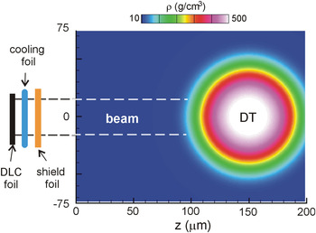
We assume cylindrical ion beams impinging on an ideal configuration of compressed DT fuel with the super-Gaussian density distribution ρ (r) = ρpeak exp[−log2(r/R)4], where r is the distance to the center, ρpeak = 500 g/cm3, R = 82 µm and the areal density is ρR = 2 g/cm2. Two configurations of the ion beams are considered in this work: perfectly collimated (constant flux within its cross section) and focused ion beams, that are studied in Sections 3 and 4, respectively (Honrubia et al., Reference Honrubia, Enriquez, Fernandez and Hegelich2013). The simulation box used for perfectly collimated beams is shown in Figure 1. Ions come from the left and propagate toward the dense core through a low density plasma at 10 g/cm3. In the particular case shown in Figure 1 of quasi-monenenergetic ions sited 5 mm far from the simulation box, a re-entrant cone is not necessary and therefore it has not been included in the calculations. Shield and cooling foils (Huang et al., 2011) have not been included either because they are too thin (around 10 µm each) to induce relevant ion energy losses. On the other hand, because the fuel is stagnated at the time of maximum compression, we assume that the DT is initially at rest with an uniform temperature of 100 eV. This corresponds to a ratio between the plasma pressure and the Fermi pressure of 2.21 at the peak density of 500 g/cm3.
(Color online) Density map of the fuel configuration considered in this work. The beam is perfectly collimated along the distance d = 5 mm from the ion source to the simulation box.

Calculations have been performed with the 2-D radiation-hydrodynamics code SARA, that includes flux-limited electron conduction, multigroup radiation transport, ion energy deposition, DT fusion reactions, and α-particle transport (Honrubia, Reference Honrubia1993a; Reference Honrubia, Velarde, Ronen and Martínez-Val1993b). This code is also coupled to a hybrid model for fast electron transport in electron-driven fast ignition (Honrubia et al., Reference Honrubia, Alfonsin, Alonso, Perez and Cerrada2006).
2.1. Ion Pulse on Target
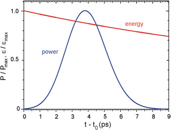
We assume that ions are generated instantaneously with a Gaussian energy distribution f(E) ∝ exp{− log2[(ε − ε0)/δε/ε0]2} where ε0 is the ion mean energy and δε/ε is the energy spread, chosen as 0.1 in this work. We refer to this distribution as “quasi-monoenergetic” throughout the paper. Instantaneous emission of the beam ions is assumed because the time of flight spread (≈3 ps) is much longer than the ion acceleration times found for the BOA scheme. Yin et al. (Reference Yin, Albright, Jung, Shah, Bowers, Hening, Fernández and Hegelich2011a; Reference Yin, Albright, Bowers, Jung, Fernández and Hegelich2011b) have shown that ions are accelerated mainly between the time of the foil relativistic transparency n e ≈ γ n c and the time when the target becomes undercritical (n e,peak ≈ n c), where n e and n c are the electron density and the critical density, respectively, and γ is the relativistic Lorentz factor. For a 100 nm thick DLC (diamond like carbon) foil illuminated by a peak laser irradiance of 5.2 × 10²⁰ W/cm2, Yin et al. obtained an enhanced acceleration time of 400 fs, still negligible when compared with the time of flight spread shown in Figure 2. Anyhow, simulations taking into account the pulse duration mentioned above show no differences when compared with the instantaneous emission used here.
(Color online) Beam power and ion kinetic energy at the left surface of the simulation box as a function of time. The incoming beam has a 5 kJ energy and a Gaussian spectrum centered at ε0 = 450 MeV with an energy spread of δε/ε0 = 0.1 (FWHM). The distance from the ion source to the left surface of the simulation box is d = 5 mm. Other parameters shown in the plot are t 0 = 55 ps, εmax = 515 MeV and P max = 1.5 PW. The beam power and ion energy on target have been obtained by using the formulas shown by Temporal (Reference Temporal2006).

Beam power and ion kinetic energy on target of a 5 kJ quasi-monoenergetic carbon ion beam generated at a distance d = 5 mm are depicted in Figure 2. This distance has been chosen in order to have a peak power about 1.5 PW and a pulse duration on target of ≈3 ps (FWHM). Note that the small time spread of quasi-monoenergetic ions allows to place the source at much higher distances than Maxwellian ions. Because beam focalization over such distances may be difficult, a number of techniques have been proposed for that. Some of them are: (1) ballistic transport (Patel et al., Reference Patel, Mackinnon, Key, Cowan, Foord, Allen, Price, Ruhl, Springer and Stephens2008; Key, Reference Key2007), (2) focusing by fields self-generated in hollow microcylinders by intense sub-picosecond laser pulses (Toncian et al., Reference Toncian, Borghesi, Fuchs, D'humiéres, Antichi, Audebert, Brambrink, Cecchetti, Pipahl, Romagnani and Willi2006) and (3) focusing by magnetic lenses (Schollmeier et al., Reference Schollmeier, Becker, Geiβel, Flippo, Blazevic, Gaillard, Gautier, Gruner, Harres, Kimmel, Nurnberg, Rambo, Schramm, Schreiber, Schutrumpf, Schwarz, Tahir, Atherton, Habs, Hegelich and Roth2008; Harres et al., Reference Harres, Alber, Tauschwitz, Bagnoud, Daido, Günter, Nürnberg, Otten, Schollmeier, Schütrumpf, Tampo and Roth2010, Hofmann et al., Reference Hofmann, Meyer-Ter-Vehn, Yan, Orzhekhovskaya and Yaramyshev2011).
Focusing of ions with Maxwellian spectra has been studied in recent years. Kar et al. (Reference Kar, Markey, Simpson, Bellei, Green, Nagel, Kneip, Carroll, Dromey, Willingale, Clark, McKenna, Najmudin, Krushelnick, Norreys, Clarke, Neely, Borghesi and Zepf2008) have demonstrated experimentally proton beam focusing by using foil rectangular or cylindrical hollow lens attached to a foil target. Offermann et al. (Reference Offermann, Flippo, Cobble, Schmitt, Gaillard, Bartal, Rose, Welch, Geissel and Schollmeier2011) have shown theoretically and experimentally that ion divergence depends on the thermal expansion of the co-moving hot electrons, resulting in a hyperbolic ion beam envelope. Using these results, Bartal et al. (Reference Bartal, Foord, Bellei, Key, Flippo, Gaillard, Offermann, Patel, Jarrott, Higginson, Roth, Otten, Kraus, Stephens, Mclean, Giraldez, Wei, Gautier and Beg2012) have shown experimentally an enhanced focusing of TNSA-protons in cone targets, inferring spot diameters about 20 µm for IFI conditions, well under the 40 µm spots required. However, as it has been shown recently by implicit PIC simulations (Qiao et al., Reference Huang, Albright, Yin, Wu, Bowers, Hegelich and Fernández2013).
For quasi-monoenergetic ions and, in particular, for those accelerated by the BOA scheme, Huang et al. (2011) have proposed recently the use of a second foil (see Fig. 1) to cool down the co-moving electrons and to absorb the trailing laser pulse that pass through the main foil after it becomes relativistically transparent (Huang et al., Reference Huang, Albright, Yin, Wu, Bowers, Hegelich and Fernández2011a; Reference Huang, Albright, Yin, Wu, Bowers, Hegelich and Fernández2011b). The electron cooling obtained in this way reduces substantially both the beam divergence and the energy spread and can be used together with the methods mentioned above for beam focusing in order to get the required spot size on target. In addition, heavier ions are less sensitive than protons to the co-moving electron expansion.
2.2. Ion Stopping
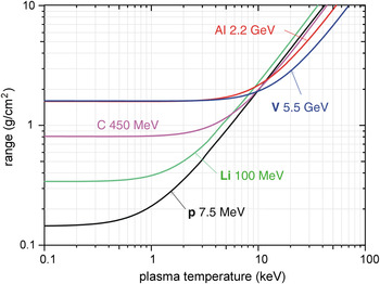
Ranges of different ion species with typical energies for FI are shown in Figure 3 as a function of the DT plasma temperature. We have used the standard stopping power formalism for classical plasmas (Trubnikov, Reference Trubnikov and Leontovich1965; Honrubia, Reference Honrubia, Velarde, Ronen and Martínez-Val1993b), which predicts range lengthening when plasma electron thermal velocities are comparable to fast ion velocity. The range lengthening effect is important for ions with Maxwellian energy distributions placed far from the target. It balances the reduction over time of the ion energy incident on the fuel, keeping the ion range almost constant (Temporal et al., Reference Temporal, Honrubia and Atzeni2002). On the contrary, as the ion energy on target is approximately constant for quasi-mononenergetic ions, range lengthening increases the volume heated by the beam and thus the ignition energies. Fortunately, the importance of range lengthening is lower for heavier ions, as shown in Figure 3. For instance, protons increase their range by one order of magnitude when the DT temperature rises from 0.1 to 10 keV, while heavier ions such as aluminum or vanadium have an almost constant range for those temperatures. Thus, a better coupling of heavier ion beams with the plasma should be expected (Honrubia et al., Reference Honrubia, Fernández, Temporal, Hegelich and Meyer-Ter-Vehn2009). Note that the range of the ions shown in Figure 3 at 10 keV is about 2 g/cm2, higher than the 1.2 g/cm2 requested for FI. However, as the ions deposit all their energy before such high temperatures are reached, the deposition range is substantially shorter in the cases analyzed here, as shown in Section 3.1.
(Color online) Range of monoenergetic ions in DT at 300 g/cm3 as a function of the plasma temperature.

It is worthwhile pointing out again that because the heavier the ion, the higher the energy they carry for a given range, the number of ions required for ignition decreases with the atomic number. It is lower by orders of magnitude for vanadium ions than for protons.
3. IGNITION ENERGIES FOR PERFECTLY COLLIMATED BEAMS
3.1. Energy Deposition
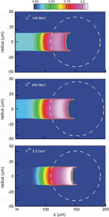
The energy deposition by lithium, carbon, and vanadium ion beams with different kinetic energies are compared in Figure 4. These energies have been chosen as those which minimize the ignition energies, as discussed in Section 3.3. Energy deposition has been computed by assuming that ions propagate in a straight line and thus neglecting the angular scattering by plasma ions, that is important for low energy ions only. Since the pulse duration is short enough compared to the resulting DT expansion (with exception of the cylindrical beam edge, where a shock wave is launched into the cold plasma), the volume heated by the beam is determined mostly by the ion energy and the range lengthening effect. The three beams shown in Figure 4 have a similar penetration into the dense core, almost up to its center. It corresponds to an areal density of around 1.6 g/cm2, higher than Atzeni's prescription of 1.2 g/cm2 (Atzeni, Reference Atzeni1999, Atzeni et al., Reference Atzeni, Temporal and Honrubia2002) due to the energy deposition in the coronal plasma. Lithium ions show a much less localized energy deposition than heavier ions, such as vanadium, due to their higher range lengthening. Note also that the energy deposition in the coronal plasma decreases for heavier ions. Thus, the coupling efficiency (defined as the energy deposited in the plasma at densities higher than 200 g/cm3) should be higher for heavier ions. In particular, for the lithium, carbon, and vanadium beams of Figure 4, the coupling efficiencies are 0.74, 0.81, and 0.89, respectively, well over the coupling efficiencies found for ions with a Maxwellian energy distribution (Honrubia et al., Reference Honrubia, Fernández, Temporal, Hegelich and Meyer-Ter-Vehn2009).
(Color online) Energy density in units of 1011 J/cm3 deposited in the target of Figure 1 by 8.5 kJ quasimonoenergetic beams (a) 140 MeV lithium ions, (b) 450 MeV carbon ions and (c) 5.5 GeV vanadium ions. The distance d from the ion source to the left surface of the simulation box is 5 mm for all beams. The dashed curves show the initial position of the density contour ρ = 250 g/cm3.

3.2. Optimal Beam Radius
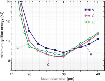
Ignition energies E ig as a function of the beam diameter for different ion beams are shown in Figure 5. They have been obtained as the minimum beam energy for which the thermonuclear fusion power has an exponential or higher growth sustained in time. The ignition energies of all beams are quite close and have a similar variation with the beam diameter. The lowest ignition energy, 8.3 kJ, is obtained for 450 MeV carbon ions. In all cases, the ignition energies rise for lower and higher beam diameters, showing almost a plateau for diameters between 20 and 40 µm, which determines the focusing requirements for IFI. For beam diameters lower than 20 µm, the energy density deposited is very high, leading to a strong plasma expansion and range lengthening with the subsequent increase of ion penetration. Ions can even pass through the compressed fuel and escape off the rear surface. For beam diameters higher than 40 µm, the ignition energies E ig rise again due to the larger spot volume that has to be heated. However, the increase of the ignition energies is less than proportional to that volume due to the reduction of α-particle losses from large spots.
(Color online) Minimum ignition energies of the target shown in Figure 1 heated by 100 MeV lithium, 450 MeV carbon and 5.5 GeV vanadium ions as a function of the beam diameter. All the beams have an energy spread of 10%. The source-core distance d is 5 mm.

3.3. Optimal Ion Energies
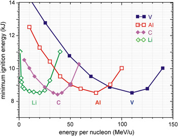
The ignition energies for different beams as a function of the ion energy per nucleon are shown in Figure 6. It is interesting to point out the remarkable result that all the ions have similar ignition energies, around 8.5 kJ for the optimal kinetic energies ε0. These optimal energies increase with the atomic number, being 140 MeV for lithium, 450 MeV for carbon, 2 GeV for aluminum, and 5.5 GeV for vanadium ions and scaling, approximately, as Z 2. This scaling is important because it prescribes the optical ion type as a function of the available ion-accelerating electric potential. The increase of the optimal ion energies with Z was also reported by Albright et al. (Reference Albright, Schmitt, Fernández, Cragg, Tregillis, Yin and Hegelich2008) and Fernández et al. (Reference Fernández, Albright, Flippo, Hegelich, Kwan, Schmitt and Yin2008) within the context of IFI capsule designs for NIF.
The shape of the curves shown in Figure 6 can be explained by taking into account that for low ion energies ε0 the pulse on target has a relatively low power, P ∝ ε01/2 and a longer duration, t pulse ∝ ε0−1/2 (Honrubia et al., Reference Honrubia, Fernández, Temporal, Hegelich and Meyer-Ter-Vehn2009). In this case, the pulse departs from the optimal one and the ignition energies E ig increase. For high ion energies, E ig increases again due to the higher fuel mass heated by the ion beam.
(Color online) Minimum ignition energies of the target shown in Figure 1 heated by quasi-mononenergetic lithium, carbon, aluminum and vanadium ions as a function of the mean kinetic energy per nucleon. The source-target distance d is 5 mm, the energy spread δε/ε = 10% and the beam diameter 30 µm in all cases.

As was mentioned in Section 2.2, the rise of the optimal ion energy with the atomic number of fast ions leads to a strong reduction of the number of ions required for ignition. For instance, around 1013 vanadium ions of 5.5 GeV ions are required to ignite the target shown in Figure 1, which is three orders of magnitude lower than that required for the standard proton fast ignition scheme (Roth et al., Reference Roth, Cowan, Key, Hatchett, Brown, Fountain, Johnson, Pennington, Snavely, Wilks, Yasuike, Ruhl, Pegoraro, Bulanov, Campbell, Perry and Powell2001).
4. IGNITION ENERGIES FOR ARRAYED BEAMS
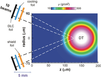
In order to reduce the IFI beam requirements, we propose a new irradiation scheme aimed at improving the beam-target coupling and igniting the compressed core more efficiently than the single beam scheme discussed in Section 3. In addition, it may lead to a further reduction of the ion number. Basically, the scheme consists of using a set of beams generated far from the imploded core and focusing them into a spot placed in the density ramp surrounding the core. Crossing beams generate a hollow cone energy deposition pattern. The scheme is shown in Figure 7, where the ions are generated in a ring placed 5 mm far from the core with a mean diameter of 2.7 mm and a tilting angle of 15°. In the reference case discussed below, we consider N = 10 ion beams generated in spots placed symmetrically at the ring with a radius r spot = 20.3 µm and area S = πr spot2 each. We assume that N = 10 beams are sufficient to have an almost homogeneous ion ring on target, as shown by Temporal et al. (Reference Temporal, Ramis, Honrubia and Atzeni2009). To illustrate the new scheme and show the advantages of more tightly focused ion beams, laser beam parameters close to those used in recent BOA experiments and simulations have been chosen. Thus, we assume a laser intensity of I L = 1021 W/cm2 and a laser-to-ion conversion efficiency η = 10%. The laser power is P L = NI LS, the laser pulse energy is E L = E ig/η, and the laser pulse duration is τ = E ig /(NI LSη). For E ig = 6.5 kJ, one obtains P L (PW) = 13 × N, E L = 65 kJ, and τ (ps) = 5/N. For the reference case N = 10 ion beams, each has a power P beam = 0.65 PW and an energy E beam = 0.65 kJ. The pulse duration would be τ = 0.5 ps, and the carbon ion mean energy 500 MeV. Lower beam powers can be obtained with longer laser pulses, that have not been studied theoretically nor experimentally yet.
(Color online) Sketch of the arrayed beams illumination scheme. Ten laser beams impinge on a ring located 5 mm far from the dense core. The ion beams generated at the rear target surface are focused on a 10 µm spot placed in the density ramp in order to generate a hollow cone energy deposition pattern.

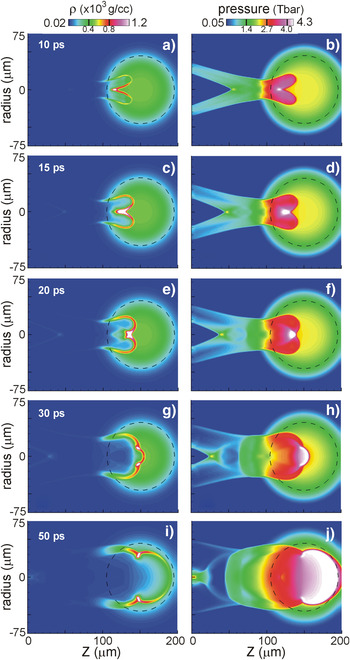
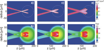
The evolution of the target shown in Figure 7 can be summarized as follows. The beams are focused into a spot placed in the density ramp such that the ions still have enough energy to penetrate further into the compressed fuel (see Figs. 8a and 8b). Most of the energy deposition in the high density fuel takes place in a hollow cone. The dense fuel within the deposition zone expands and launches a strong shock wave that propagates toward the axis, where the shocks collide and compress the fuel further to very high densities (≈1200 g/cm3) (see Fig. 8c). The pressure peaks there (see Fig. 8d) and increases its strength while propagating toward the right (see Figs. 8e and 8f). Ignition starts in this high-pressure region (see Figs. 8g and 8h) and propagates through the dense and cold fuel (see Figs. 8i and 8j). In this irradiation scheme, ignition is produced by the collision of two shocks on the axis, not by the direct heating of the fuel, being in this sense a variant of the shock ignition scheme (Betti, Reference Betti, Zhou, Anderson, Perkins, Theobald and Solodov2006). The main advantage of this irradiation scheme is that ignition can be achieved with substantially lower beam energies. For instance, a beam of 500 MeV carbon ions focused onto a 10 µm spot diameter at the depth of z = 100 µm on the axis requires 5.7 kJ for ignition, which is approximately 2/3 of the energy required for a single beam, as shown in Figure 5. It is worthwhile to emphasize that this improvement is not due to a sharper ion-beam focusing per se, as clearly shown in Figure 5 for a single beam. Contrary to the single-beam case, the success of the array scheme depends on a sharper focusing of the ion beams able to generate strong converging shock waves. For instance, if the beams could be focused into a 5 µm spot, the ignition energy would be reduced to 4.5 kJ, roughly a half of that obtained for a single beam. The dependence of the ignition energy on the spot diameter is shown in Figure 9. For diameters as large as 15 µm, the focusing beams scheme still reduces the ignition energy by ≈20% when compared with the single beam scheme. For larger diameters, the differences between both schemes are not high enough to balance the difficulties of beam focusing. Thus, its practical implementation is limited by the possibility of beam focusing into 10 µm spots, smaller than those required for single beams (30 µm), from distances of millimeters, which is a challenging task.
(Color online) Ion density (left panels) and pressure (right panels) evolution of the target shown in Figure 7 heated by carbon ion beams of 500 MeV and δε/ε = 0.1 focused onto a 10 µm spot sited at z = 100 µm. Ignition is produced by the shock waves launched by the ion beams that collide on the axis.

(Color online) Sensitivity of the target heating on beam focusing. Energy deposition of 500 MeV carbon ion beam is shown in the upper panels and DT pressure at 15 ps in the lower panels. The focusing parameter d foc, defined as the overlapped minimum beam diameter on axis, and the ignition energies E ig are: (a, b) d foc = 5 µm, E ig = 4.5 kJ; (c,d) d foc = 10 µm, E ig = 5.7 kJ; and (e,f) d foc = 15 µm, E ig = 7 kJ.

The focused beams scheme presented above has some advantages when compared with that described in Temporal et al. (Reference Temporal, Honrubia and Atzeni2008; Reference Temporal, Ramis, Honrubia and Atzeni2009) for proton FI. In this latter scheme, the imploded target is first irradiated by a number of proton beamlets with an annular set up and a total energy of 1 kJ followed, after a time delay, by a second cylindrical beam of 7 kJ. The penetration of the central part of the cylindrical beam is blocked by the higher densities generated on the axis by the annular beamlets. Meanwhile the outer part of the cylindrical beam penetrates further and generates a cylindrical shock that collides on the axis and ignites the DT fuel ahead the energy deposition of the central part of the ion beam. On the contrary, in our scheme, the shocks are produced directly by the whole beam energy deposition without any blocking effect and thus the scheme should be more effective. In addition, in the scheme of Temporal et al. (Reference Temporal, Ramis, Honrubia and Atzeni2009), ignition is very sensitive to the time delay between the annular beams and the main cylindrical beam while in ours all beams are fired simultaneously. It is also worth noting that the focusing requirements are similar in both schemes because the diameter of each beamlet is 10 µm, just the same than the spot required for our beams array.
5. CONCLUSIONS
In order to extend the possibilities of IFI with quasi-monoenergetic ions, we consider different ion species and propose a new irradiation scheme with arrayed beams. Specifically, fast ignition by quasi-monoenergetic lithium, carbon, aluminum, and vanadium ions have been analyzed for a simplified DT fuel configuration with a peak density of 500 g/cm3. Using middle or heavy ion beams has the advantage of reducing substantially, by orders of magnitude, the number of ions required for ignition. Ideal ion beams with a uniform flux within its cross section and an energy spread of 10% perfectly focused into such a configuration have been analyzed. Simulations show that the minimum ignition energies, about 8.5 kJ, are similar for the ions studied here despite being obtained with very different kinetic energies. We should point out that those ignition energies have to be considered as a lower limit due to the strong assumptions made. Anyhow, taking into account laser-to-ion conversion efficiencies around 10% or higher found so far (Hegelich et al., Reference Hegelich, Jung, Albright, Fernandez, Gautier, Huang, Kwan, Letzring, Palaniyappan, Shah, Wu, Yin, Henig, Hörlein, Kiefer, Schreiber, Yan, Tajima, Habs, Dromey and Honrubia2011), it would be possible to fast ignite a pre-compressed target with laser energies of about 100 kJ. It is worth mentioning the high laser-to-proton conversion efficiencies (15%) measured recently in target normal sheath acceleration experiments (Brenner et al., Reference Brenner, Robinson, Markey, Scott, Gray, Rosinski, Deppert, Badziak, Batani, Davies, Hassan, Lancaster, Li, Musgrave, Norreys, Pasley, Roth, Schlenvoigt, Spindloe, Tatarakis, Winstone, Wolowski, Wyatt, Mckenna and Neely2014).
In addition to the collimated beam studies, we propose a new target irradiation scheme based on an array of focused quasi-monoenergetic ion beams. As a single 100 kJ short-pulse laser cannot easily envisaged, the single beam scheme would be based on the combination/superposition of multiple beamlets to get the required energy, in a similar way that the ion beam array proposed here. The difference is that in our scheme the beamlets should be focused onto a spot sited on the target density ramp. That may be a better way of deploying individual FI laser beams (or individual clusters of laser beams).
Our results show that the arrayed beam scheme reduces substantially the ignition energies obtained for single beams, provided that the ion beams can be adequately focused into 10 µm spots. Of course, to achieve such focusing will require a substantial reduction of the transverse temperature of co-moving electrons, for instance, by using a second cooling foil (Huang et al., 2011), which shall be used together with one of the focusing techniques outlined in Section 2.1. The price to be paid for the reduction of the ignition energy would be the 3-D focusing of the beam array, which may have a similar or even higher difficulty than using lasers with energies above 100 kJ.
Future studies of IFI will include realistic beam and target configurations, and longer laser pulses in order to obtain more accurate estimations of the laser and ion beam requirements.
ACKNOWLEDGMENTS
This work was partially supported by the research grant ENE2009-1168 of the Spanish Ministry of Education and Research, was undertaken as part of the HiPER preparatory project, and used resources and technical assistance from the CeSViMa HPC Center of the Polytechnic University of Madrid. This work was also partially supported by the LDRD program at Los Alamos National Laboratory, and by the US DOE.