I. INTRODUCTION
The ubiquitous lithium-ion battery (LIB) has been developed over the past four decades into the most successful portable power source now available.Reference Tarascon and Armand1,Reference Oudenhoven, Baggetto and Notten2 It offers among the best energy density, cost, performance, and safety characteristics, and so finds application in a wide range of electric vehicles, aerospace and portable electronics, and tools. Although it has been under continuous development, the underlying chemical physics of this critical technology remains poorly understood. The charge/discharge cycle of these batteries can be described as a process of intercalation and deintercalation of Li+ ions between the host material electrodes. The dynamics during electrochemical cycling and Li transport in these materials are of great importance in determining failure mechanisms and suggesting modifications for improved performance. Ex situ observations of changes in the crystal structure and chemistry have proven useful for understanding the structure and property relationships.Reference Shao-Horn, Croguennec, Delmas, Nelson and O’Keefe3 However, the dynamic nature of the atomic process of electrochemical cycling requires in situ methods with the ability to image atomic transport directly, as well as chemical reactions at the nanometer scale. Previous in situ studies have mainly used x-rayReference Courtney and Dahn4 and neutronReference Sharma, Peterson, Elcombe, Avdeev, Studer, Blagojevic, Yusoff and Kamarulzaman5 probes. Recently, there have been several in situ transmission electron microscopy (TEM) studies on LIBs.Reference Huang, Zhong, Wang, Sullivan, Xu, Zhang, Mao, Hudak, Liu, Subramanian, Fan, Qi, Kushima and Li6–Reference Xie, Tu, Su, Du, Zhang, Zhu, Cao and Zhao20 This technique, combined with x-ray spectroscopy and/or electron energy-loss spectroscopy (EELS), has the unique merit of directly imaging and analyzing the electrochemical process and the chemical state of the ions, with a subnanometer spatial resolution, in real time. However, the current techniques for in situ TEM studies of lithiation and delithiation processes require a specialized TEM holder, in which a LIB cell is set up. The materials suitable for making a TEM LIB cell are limited. For general interest, it is necessary to develop an inexpensive and easily applied approach, which allows observation of the electrochemical reaction in real time.
Recently, we have discovered that the electron beam itself in a TEM can directly trigger Li transport on amorphous C (am-C) films, resulting in lithiation of carbons without external fields. The Li transport and reaction with carbons are powered by the induced electric field due to electron beam irradiation of a Li-containing electrolyte. This is equivalent to the charging process if the am-C is considered as the anode. The dynamics of this charging process can then be imaged directly and analyzed in real time.
II. EXPERIMENTAL
Li+ ions involving transport and lithiation of carbons were released from a Li4SiO4 crystal (Alfa Aesar, Inc.) during decomposition under the electron beam. Li4SiO4 has been used as a solid-state electrolyte due to its high ionic conductivity.Reference Nakagawa, Kuwata, Matsuda and Kawamura21 The decomposition was due to the reaction: Li4SiO4 → SiO2 + 4Li+ + O2↑.Reference Jiang22 The decomposed phase is Li-free amorphous SiO2. This was confirmed by EELS analysis (Supplementary Information (SI)). The am-C films were “lacey C” support material on a Cu grid for a TEM specimen (Ted Pella, Inc.). Li4SiO4 crystals were mounted on the am-C by picking up the Li4SiO4 particles floating in acetone on am-C covered Cu grids. Real-time spectroscopy experiments were carried out using a JEOL-2010F TEM equipped with a field-emission electron source (JEOL Ltd., Japan) operating at 200 kV and a Gatan Enfina© electron spectrometer. The energy resolution of EELS was about 1.0 eV measured at the full width at half maximum of zero-loss peak. Low energy-loss spectra and Li K-edge EELS spectra were recorded in the image mode and a 2.0 mm EELS entrance aperture was used.
III. RESULTS AND DISCUSSION
The Li transport and lithiation of carbons were confirmed by real-time EELS analysis in the following two different experimental setups [Figs. 1(a) and 3(a)]. Both sets of EELS data (similar to soft-x-ray absorption near-edge spectroscopy, XANES) were acquired in the image mode from the am-C film near a Li4SiO4 particle, the acquisition areas defined by the EELS aperture are the same, and the current density of the electron beam was similar.
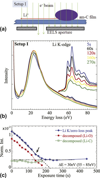
(a) Schematic of experimental Setup I. (b) A series of real-time EELS. The inset shows the background subtracted Li K-edge. (c) Integrated intensity of the Li K-edge, with the decomposed components of Li–O and Li–C.

In Setup I, as shown in Fig. 1(a), both the Li4SiO4 particle and the am-C film, where the EELS spectra were acquired, were illuminated simultaneously during data acquisition. Some selected time-resolved EELS spectra are shown in Fig. 1(b). (A full time series is given in S.I.) It is seen that there are significant changes in the Li K-edge spectra. With an increased exposure, the Li K-edge changes gradually from two-peak to one-peak structure. Most importantly, the intensity of the Li K-edge drops sharply at the beginning of the exposure. This is seen more clearly in the profile of integrated intensities, which are normalized to the intensity of the zero-loss peak [Fig. 1(c)]. (The spectra were deconvoluted from the plural scattering and so reflect Li composition change.Reference Egerton23) Initially, the amount of Li within the area defined by the EELS aperture decreased almost linearly with exposure until about 160–180 s of irradiation. The continued exposure produced little change in the Li content.
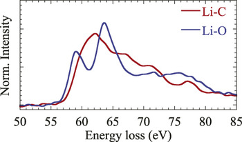
It is noticeable that the two-peak fine structure of the Li K-edge in Fig. 1(b) is slightly different from the reference Li K-edge of the Li2O crystal.Reference Jiang and Spence24 The difference is attributed to the mixture of two types of bonding states, i.e., Li–O and Li–C, respectively. The Li K-edge in Li–O exhibits a characteristic two-peak structure, while it is a single peak in Li–C, and its threshold shifts about 2 eV to higher energy (Fig. 2). This assignment has been confirmed from both the real-time EELS analysis and simulations detailed in S.I. Thus, the Li K-edge in Fig. 1(b) can be decomposed into contributions from Li–O and Li–C, respectively, using the reference spectra in Fig. 2 (see S.I.). The decomposed intensities are also plotted in Fig. 1(c). The results suggest that only a small portion (about one fifth) of Li is involved in forming Li–C bonds, i.e., lithiation of carbons, while the majority of the remainder is oxidized by the O released from the decomposed Li4SiO4. It is noticeable that the Li–O component drops rapidly to almost zero after 200 s of exposure. By contrast, the Li–C component remains constant throughout.
Extracted spectra of Li–O and Li–C bonding states.

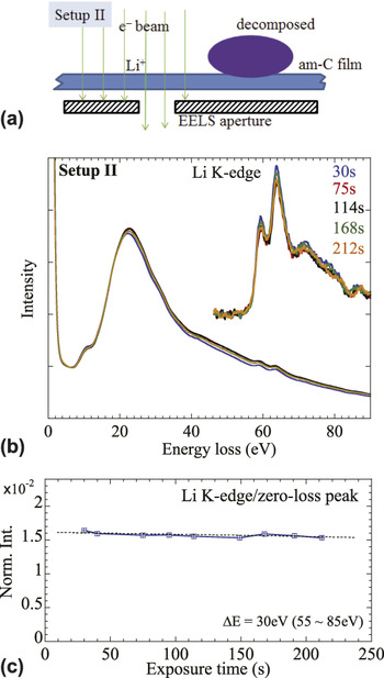
To understand the decrease in the Li–O intensity, we designed another set of experiments, Setup II [Fig. 3(a)]. In this experiment, only the am-C film was under electron illumination during real-time data acquisition, after the Li4SiO4 particle was preilluminated and decomposed. Contrary to Setup I, the Li K-edge EELS spectra show almost no change [Fig. 3(b)]. Most significantly, the decreased rate of integrated intensities [Fig. 3(c)], normalized to the intensity of the zero-loss peak, is now much slower compared to that observed in Setup I and is negligible.
(a) A schematic of experimental Setup II. (b) A series of real-time EELS. The inset shows the background subtracted Li K-edge. (c) Integrated intensity of the Li K-edge. Dotted line is a guide.

It is worth noting that in both setups, the Li4SiO4 particles have been decomposed before in situ EELS data were acquired, and the only difference between these two experiments was that the decomposed particle was still under electron beam irradiation in Setup I, but it was not in Setup II. The large difference in the rate of decrease between Setup I and Setup II indicates that knock-on sputtering or mechanisms involving radiolysis could not be responsible for the rapid loss of Li+ observed in Setup I. Otherwise similar decrease rates would be observed, since knock-on sputtering and radiolysis are due to elastic or inelastic collisions between energetic electrons and atoms. Therefore, the rapid decrease of the Li intensity must be associated with the coillumination of the decomposed Li4SiO4 particle nearby, which is the only significant difference between the two experiments.
The decomposition of Li4SiO4 under electron irradiation is caused by an induced electric field due to ionization.Reference Jiang22 When excited by energetic incident electrons, the ionization process ejects Auger and secondary electrons near the surface of the Li4SiO4 particle into a vacuum. Since Li4SiO4 is a good insulator for electrons, the charge balance cannot be immediately restored by electrons from the surroundings through the supporting am-C film.Reference Jiang22,Reference Cazaux25 A positively charged shell is thus formed around the Li4SiO4 particle, resulting in highly mobile Li+ ions flooding the supporting am-C film.
Suppose that I E is the current of emitted electrons flowing out of the particle and I A is the current of electrons flowing into the particle from the supporting am-C film, in compensation. The charge build-up rate in the particle is approximatelyReference Jiang22
 $${{{\rm{d}}Q} \mathord{\left/ {\vphantom {{{\rm{d}}Q} {{\rm{d}}t}}} \right. \kern-\nulldelimiterspace} {{\rm{d}}t}} = {I_{\rm{E}}} - {I_{\rm{A}}}\quad .$$
Beam electrons do not contribute to the charge accumulation directly, because the specimen is thin enough to be transparent to the incident electrons. Since the positive potential on the surface suppresses the yields of emissions,Reference Cazaux25I E decreases with exposure time due to a positive charge accumulation in the particle. By contrast, the charge accumulation enhances the attraction of surrounding electrons into the particle, so I A increases. Thus, at the beginning of irradiation, I E(0) has its maximum value but then drops with time, while I A(0) = 0 but increases gradually. At a certain time t 0, I E(t 0) and I A(t 0) reach balance, so that
 $${\left( {{{{\rm{d}}Q} \mathord{\left/ {\vphantom {{{\rm{d}}Q} {{\rm{d}}t}}} \right. \kern-\nulldelimiterspace} {{\rm{d}}t}}} \right)_{t = {t_0}}} = 0\quad .$$
Meanwhile, the accumulation of charge also reaches its maximum at time t 0, i.e.,
 $${Q_{{\rm{max}}}} = \int_0^{{t_0}} {\left[ {{I_{\rm{E}}}(t) - {I_{\rm{A}}}(t)} \right]{\rm{d}}t} \quad .$$
In theory, Q max is determined not only by the intrinsic physical and chemical properties of Li4SiO4, but also by the illumination conditions, the beam current density, and physical contact between the particle and am-C film.Reference Jiang22
Further irradiation (i.e., t > t 0) should not change Q max as long as the particle is exposed to the same electron beam, because  ${I_{\rm{E}}}({t_0}) = {I_{\rm{A}}}({t_0}) \ne 0$, unless the particle is decomposed. Intrinsically, this change is mainly caused by the change in the resistivity of the new phase.Reference Jiang22 Amorphous SiO2 has a band gap exceeding 9.0 eV,Reference Garvie, Rez, Alvarezb and Buseck26 which is larger than the calculated 5.24 eV band gap of Li4SiO4 (Ref. Reference Duan and Parlinski27) so that decomposition may increase the particle's resistivity. Therefore, in Setup I, the charge remains as long as am-SiO2 is continuously exposed to the same electron beam. As a result, the electric field induced by the fixed charges in the am-SiO2 particle drives away all the mobile Li+ ions within the range in which the electric field is strong enough to overcome the binding energy of a Li+ ion to am-C. By contrast, in Setup II, the charges were neutralized by electrons from the surroundings, since the beam was off the decomposed particle. Therefore, the dispersed Li ions on the am-C around the particle remain. There is no driving force to cause Li transport when the induced electric field is turned off.
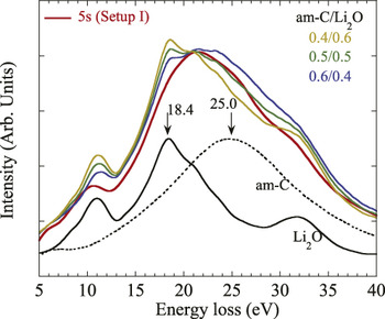
We conclude that the decrease of the Li content observed in Setup I is due to Li transport on the am-C, driven by the induced electric field on nearby decomposed am-SiO2. Apparently, the mobile Li is in ionic form, bonded to O. On the am-C, these mobile Li+ ions are in the form of ultrathin layers or clusters. This conclusion results from an analysis of plasmon excitations. As shown in Fig. 4, the plasmon peak for Li-covered am-C is significantly different from that of am-C and Li2O nanoparticles. In Li2O, the bulk plasmon has a sharp peak at about 18.4 eV, while am-C has a broad peak around 25.0 eV. The plasmon peak of Li2O is not visible in the Li covered am-C. The weighted sums of Li2O and C are also compared in Fig. 4. This clearly shows that the bulk plasmon peak of Li2O was strongly suppressed in the Li-covered am-C, indicating that the Li+ layers on am-C film are ultrathin.Reference Jiang, Su, Spence, Zhou and Qiu28
Comparison of the EELS spectrum recorded from the Li covered am-C with reference spectra of Li2O and am-C, and their weighted sums. The ratios of the weighted sum are listed.

It follows that Li+ ions in the Li–O form are responsible for Li transport driven by an induced electric field. By contrast, Li+ ions in the Li–C form are stable under the same strength of electric field. Since the Li–O species are absorbed on the surface of the am-C and the Li–O bond is ionic (polarized by electrostatic attraction between a positive Li+ ion and a negative O2− ion), Li–O can be easily decoupled by the induced electric field, resulting in Li+ transport and O2− desorption.
While the Li–C bond is less polarized than Li–O, it could be relatively stable under an electric field. Since disordered carbons show a similar short-range structure to graphite or graphene,Reference Claye and Fischer29 the intercalated Li could either be inserted between layers of graphite segmentsReference Sato, Noguchi, Demachi, Oki and Endo30 or “coat” both sides of graphene sheets,Reference Dahn, Zheng, Liu and Xue31 forming local clusters resembling the structure of LiC6.Reference Kganyago and Ngoepe32 This was confirmed by the similarity of the Li K-edge EELS between the lithiated am-C and crystal LiC6, since EELS is more sensitive to the local structure around the absorbing atom rather than long-range order (see S.I.).
IV. CONCLUSION
We have shown that the Li transport and lithiation of carbons can be achieved under electron irradiation alone, without an external power supply. The driving force is the electric field induced by excitations and ionizations in an electrolyte particle. This phenomenon is consistent with the Li transport and lithiation processes which occur during electrochemical cycling in a LIB cell, in which am-C as an anode can be charged by inserting Li+ ions driven by an applied electric field during a charging process. The mechanism of charge transport under the electric field occurs as Li+.
The material as a good electrolyte should be a good insulator to electron, but a good conductor for Li+ ions. Since the driving force for Li+ ion diffusion is the induced electric field in the insulating material, the former condition is also crucial for building up positive charges by electron irradiation.Reference Jiang22,Reference Cazaux25 The latter guarantees that the material has low-energy barrier for Li+ ion diffusion. The combination of these two conditions, which are characteristics of a good electrolyte, causes the material to be susceptible to an electron beam. The beam damage not only results in phase decomposition, but also drives Li+ ions collectively toward the electric ground. Therefore, this work raises reasonable doubts about operating a full LIB cell (electrodes and electrolytes) under electron beam illumination. The comment is that the electrolyte should be avoided from exposure to electron beam during the in situ TEM study of electrochemical process in a LIB. The exposure may at least produce a potential barrier preventing Li+ ions from passing through.
Supplementary Material
To view supplementary material for this article, please visit http://dx.doi.org/jmr.2014.550.
ACKNOWLEDGMENTS
We thank J. Spence for useful discussions. The use of facilities within the Cowley EM Center in the Center for Solid State Science at Arizona State University is acknowledged.