1. Introduction
With the development of robot control and robotic perception technologies, including machine vision, robotic systems have become increasingly capable of performing precise and repetitive tasks. However, most existing achievements still focus on the manipulation of rigid objects, while operations such as recognition, grasping, placing, and configuration control of deformable objects, such as fabrics, remain highly challenging.
The manipulation and handling of fabric is an essential part of daily life [Reference Longhini, Wang, Garcia-Camacho, Blanco-Mulero, Moletta, Welle, Alenyà, Yin, Erickson, Held, Borràs and Kragic1]. With the increasing level of automation and intelligence in both production and service environments, there is a growing demand for robotic systems capable of handling flexible textiles, especially in settings such as hotels, hospitals, fabric processing, and automated production lines. However, the deformability, irregularity, and highly diverse configuration space of fabrics [Reference Cusumano-Towner, Singh, Miller, O’Brien and Abbeel2] make it difficult for existing robotic systems to accurately perceive and reliably manipulate them. As a result, fabric handling remains a representative challenge in robotic manipulation of deformable objects.
For practical fabric handling, the key lies in the detection and selection of grasping points. Fabric appearance is easily affected by shape variation, wrinkles, texture, shadows, lighting, and occlusion, which significantly increases the difficulty of stable grasping point perception. In addition, the same mechanical action may lead to different fabric states, further increasing the uncertainty of robotic manipulation [Reference Jiménez3]. Although learning-based methods have recently achieved promising progress in tasks such as fabric unfolding, dressing, and folding, many of these methods still rely on large-scale training data, complex sensing configurations, or high deployment cost. In contrast, for constrained industrial scenarios such as towel and bed-sheet handling, lightweight and easy-to-deploy solutions are often more desirable. Moreover, for thin and deformable fabrics, ordinary depth cameras may provide unstable local depth measurements near lifted or folded corners, making precise corner height estimation difficult, while the introduction of depth sensing also increases hardware complexity, computational cost, and deployment burden. Therefore, in this work, using only RGB images should be regarded as both a practical design choice for the target scenario and a limitation of the current system: it reduces sensing and deployment complexity but also excludes direct depth cues that may be beneficial in more general fabric manipulation settings.
Motivated by these considerations, this paper focuses on fabric corner recognition for small- to medium-sized solid-color fabrics in constrained tabletop environments using only RGB images. Rather than redesigning the core line segment detector (LSD) itself, we enhance line perception for the fabric corner recognition task and further recover task-relevant geometric structures from fragmented line detections. Specifically, we propose an LSD-enhanced line perception and structural recovery framework, in which a Line Segment Classification, Deletion, and Completion Tool (LS-CDCT) is designed to repair, filter, merge, complete, and organize line segment detections into corner-supporting line structures. Based on the recovered line segment chains, we further develop a geometric fabric corner recognition method for both internal and edge-visible corners and deploy the resulting corner-to-grasp pipeline on a single-arm robotic system for automatic fabric corner grasping.
The main contributions of this paper are as follows:
-
• An LSD-enhanced line perception front-end is developed for constrained fabric scenes, improving the suitability of line detections for subsequent fabric corner reasoning under different image resolutions and texture-induced disturbances;
-
• An LS-CDCT is proposed to recover task-relevant geometric structures from fragmented line detections through repair, filtering, merging, completion, and chain-level organization, thereby enabling robust fabric corner recognition;
-
• A corner-driven robotic grasping pipeline is designed to map recognized fabric corners and their geometric orientation into executable grasping actions using a single-arm robot and a gripper with feedback signals, without relying on precise depth estimation.
2. Related work
There are comprehensive literature reviews on the broad field of fabric manipulation [Reference Longhini, Wang, Garcia-Camacho, Blanco-Mulero, Moletta, Welle, Alenyà, Yin, Erickson, Held, Borràs and Kragic1, Reference Garcia-Camacho, Longhini, Welle, Alenyà, Kragic and Borràs4–Reference Yin, Varava and Kragic6]. Here, we focus on areas more closely related to this work, including fabric model reconstruction, vision-based fabric grasping point detection, and robotic fabric manipulation methods.
Manipulating fabrics with unknown configurations presents significant challenges, and model reconstruction helps quantify fabric states, facilitates the analysis of specific geometric features, and improves the robot’s ability to manipulate flexible fabrics. Existing studies have explored simplified operation models [Reference Kita and Kita7–Reference Li, Xu, Yue, Wang, Chang, Grinspun and Allen9], learning-based dynamic modeling approaches [Reference Lin, Wang, Huang and Held10], template matching for manipulation [Reference Phyu, Funakubo, Fumiya, Shinichiro and Minami11, Reference Wang, Li, Zamora and Coros12], and simulation-based operation verification [Reference Runia, Gavrilyuk, Snoek and Smeulders13–Reference Lin, Wang, Olkin and Held15]. These studies provide diverse solutions for understanding and modeling deformable fabric behavior.
In addition to model reconstruction, many studies have focused on directly detecting fabric grasping points, investigating how grasp point selection affects manipulation outcomes [Reference Borras, Alenya and Torras16] and how to accurately identify key grasping points to improve the precision and efficiency of robotic manipulation. More generally, recent studies on robotic grasp detection have reviewed both analytic and data-driven approaches, highlighting the broader methodological context of grasp point perception in robotic manipulation [Reference Dong and Zhang17]. Early works utilized the Canny operator to extract fabric corner information [Reference Triantafyllou and Aspragathos18], which inspired subsequent geometry-based grasping point detection methods. Existing approaches include geometry-based detection [Reference Maitin-Shepard, Cusumano-Towner, Lei and Abbeel19, Reference Zhai, Zhang, Dai, Xia, Wen and Shi20], garment region segmentation [Reference Qian, Weng, Zhang, Okorn and Held21, Reference Shehawy, Rocco and Zanchettin22], point cloud recognition [Reference Caporali and Palli23], 3D descriptor representation [Reference Ramisa, Alenya, Moreno-Noguer and Torras24], and related grasping point selection methods for other deformation-sensitive objects based on geometric or model-based reasoning [Reference Du, Liu and Zhang25], as well as random decision forests recognition [Reference Doumanoglou, Kargakos, Kim and Malassiotis26] and deep learning-based grasping point detection [Reference Garcia-Camacho, Lippi, Welle, Yin, Antonova, Varava, Borras, Torras, Marino, Alenya and Kragic27–Reference Saxena and Shibata35]. These methods have significantly improved the precision, efficiency, and stability of robotic manipulation of flexible fabrics.
In terms of control strategies, studies have proposed dynamic control [Reference Ha and Song29], dynamic manipulation frameworks for deformable-object operations [Reference Gu, Zhang, He and Yu36], Fourier transform shape servoing [Reference Navarro-Alarcon and Liu37], perception-based manipulator control [Reference Cui, Huang, Lu and Chu38], RGB-D semantic segmentation unfolding strategies [Reference Zhu, Wang, Freer, Chang and Gao30], and a unified framework based on visual correspondence [Reference Wu, Lu, Wang, Wang and Dong31]. In task planning, strategies such as task decomposition and optimization [Reference Osawa, Seki and Kamiya39], action graph modeling optimization [Reference Camacho, Sol and Ribas28], and path planning with feedback control [Reference Yuba, Arnold and Yamazaki40] have been proposed. In terms of multi-arm collaboration, studies have explored dual-arm robotic fabric manipulation evaluation [Reference Garcia-Camacho, Lippi, Welle, Yin, Antonova, Varava, Borras, Torras, Marino, Alenya and Kragic27], probabilistic planning-guided decision-making [Reference Doumanoglou, Kargakos, Kim and Malassiotis26], multi-stage operation processes [Reference Bersch, Pitzer and Kammel41, Reference Kuribayashi, Yoshioka, Onda, Yamazaki, Wu, Arnold, Takase and Yamazaki42], deep learning-based strategy optimization [Reference Tamei, Matsubara, Rai and Shibata43, Reference Gu, He and Yu44], and efficient fabric folding through dual-arm manipulation and action design [Reference He, Meng, Sun, Wang and Meng45]. Additionally, methods combining perception and reasoning for manipulation [Reference Cusumano-Towner, Singh, Miller, O’Brien and Abbeel2, Reference Kita and Kita7] and end-effector grippers for fabric manipulation [Reference Borras, Alenya and Torras16, Reference Salleh, Seki, Kamiya and Hikizu46–Reference Lee, Chen, Chen and Rojas48] and flexible grasping [Reference Fu, Yu, Guo, Zheng and Gan49] have also been studied.
Although the field of fabric manipulation has developed rapidly in recent years, existing research still faces several limitations. Traditional methods based on edge extraction, geometric reasoning, or model reconstruction often require careful parameter tuning and may be sensitive to uncertainty in real-world environments. Methods relying on multimodal perception or 3D sensing can provide richer geometric information, but for thin and deformable fabrics, ordinary depth cameras may struggle to stably capture accurate local corner height, while also increasing hardware complexity and deployment cost. Learning-based methods have shown strong performance in object recognition and key point detection, but they usually require large amounts of labeled data, substantial computational resources, and complex training procedures. These limitations hinder the practical deployment of many existing methods in industrial environments that demand efficiency, low cost, and ease of use.
Fabric corners are prominent and easily manipulable features of fabric morphology, and their accurate perception directly affects the success of robotic grasping and subsequent operations. Therefore, this paper focuses on the precise detection and robotic grasping of fabric corners for small- to medium-sized solid-color fabrics in constrained tabletop environments. Different from methods that primarily rely on high-cost sensing or heavy training pipelines, this work aims to achieve efficient fabric corner recognition and grasping through an LSD-enhanced line perception process, structural recovery of fragmented line detections, and lightweight geometric reasoning. This provides a practical foundation for more complex fabric manipulation tasks.
3. Method
3.1. Principle overview
In fabric manipulation, fabric corners are among the most direct and practically useful grasping features. A common strategy is to combine edge detection methods, such as Canny or Scharr, with corner detectors such as Harris, or to use geometry-based visual cues for grasp point localization [Reference Dong and Zhang17, Reference Maitin-Shepard, Cusumano-Towner, Lei and Abbeel19, Reference Zhai, Zhang, Dai, Xia, Wen and Shi20]. However, for deformable fabrics, this strategy is often disturbed by wrinkles, texture, shadows, and illumination variation. As a result, the extracted edge information is usually noisy, fragmented, and geometrically unstable, which may lead to irrelevant interfering edges and false corner points. Moreover, edge responses are typically discrete and lack reliable structural continuity, which limits their suitability for subsequent corner reasoning and robotic grasping.
Compared with edge-based representations, line segment detection provides a more compact and geometrically meaningful description of visible fabric boundaries. Although raw line detections may still be affected by wrinkles or shadows, they preserve explicit directional and positional information, which is beneficial for subsequent filtering, structural recovery, and corner analysis. Since visible fabric corners are essentially formed by the intersection of boundary-supporting line structures, line segment detection provides a natural basis for fabric corner perception. Therefore, instead of directly reasoning from raw edge responses, this work adopts a line-based representation and further enhances it for the fabric corner recognition task.
A variety of line segment detection methods have been developed, such as the Hough Transform [Reference Duda and Hart50], LSD [Reference Von Gioi, Jakubowicz, Morel and Randall51], CannyLines [Reference Lu, Yao, Li and Li52], and FLD (Fast Line Detector) [Reference Lee, Lee, Zhang, Lim, Chung and Suh53]. Among them, LSD offers a good balance of accuracy, robustness, and computational efficiency, making it suitable for practical robotic perception. In this work, LSD is used as the front-end line detector. However, rather than directly using its raw outputs, we enhance line perception for constrained fabric scenes and further recover task-relevant geometric structures from fragmented line detections. Specifically, for industrial tabletop scenarios with relatively clean backgrounds, background removal is first employed to focus perception on the fabric region. On this basis, we develop an LSD-enhanced line perception and structural recovery framework, in which the detected line segments are repaired, filtered, merged, completed, and organized through the proposed LS-CDCT. The recovered line segment chains are then used for geometric fabric corner recognition and subsequent robotic grasping.
3.2. LS-CDCT: Structural recovery of fabric-supporting line representations
The proposed LS-CDCT serves as the core structural recovery module of the overall framework. Starting from fragmented line detections produced by the LSD-enhanced front-end, LS-CDCT aims to recover geometrically meaningful and corner-supporting line structures for subsequent fabric corner reasoning. Rather than directly using raw line detections, this module progressively suppresses noise, restores incomplete boundary fragments, organizes connected structures, and refines chain-level geometry.
Specifically, LS-CDCT addresses four main structural problems in fabric line perception:
-
• inconsistent usefulness and quantity of detected line segments across different image resolutions;
-
• the coexistence of informative short edge fragments and irrelevant short noisy segments;
-
• incomplete or disconnected line structures at fabric edges and crease regions;
-
• disordered local line configurations around corners and folds.
The overall process is illustrated in Figure 1. Given an input fabric image, LS-CDCT transforms raw line detections into refined line segment chains and their associated geometric attributes, which provide the structural basis for subsequent corner detection and robotic grasping.
Overview of the LS-CDCT-based structural recovery process. The figure shows the main stages of line processing, including resolution-aware preprocessing, LSD line detection, segment repair/filtering/merging, segment completion and chain construction, and edge/internal chain filtering with corner completion. Representative local changes during line refinement are highlighted by red circles and zoom-in views.

Figure 1. Long description
This figure shows the overall LS-CDCT-based structural recovery framework. The input fabric image is processed by resolution-aware preprocessing, LSD line detection, segment repair, filtering, merging, segment completion, chain construction, and edge/internal chain filtering with corner completion. The output is a refined set of line segment chains and their attributes, including chain ID, endpoints, endpoint segments, total length, number of sub-segments, and segment set. Representative local refinements are highlighted by red circles and zoom-in views.
Comparison of line segment detection results before and after preprocessing.

Figure 2. Long description
This figure compares six fabric images under different resolutions. Each column shows the original image, the background-removed image, the raw line segment detection result, and the detection result after preprocessing. The figure illustrates that high-resolution images may produce many texture-induced line responses, while resolution-aware preprocessing suppresses these responses and preserves major fabric-supporting edge structures.
3.2.1. Resolution-aware preprocessing
Since the proposed framework is intended to process images captured by different RGB cameras under varying resolutions, the first step is to improve the suitability of line perception under resolution-dependent appearance changes. In particular, for towel-like fabrics with fluffy texture, high-resolution images often contain fine surface details that are easily mistaken for line structures, while lower-resolution images tend to suppress such texture-induced interference. Therefore, a resolution-aware preprocessing strategy is introduced before structural recovery.
To reveal this effect, we first perform line segment detection on towel images of size 27 cm
 $\times$
27 cm under different image resolutions, and the results are shown in Figure 2(III). The towel material is non-smooth and contains fluffy surface texture. The results show that, when the image resolution is low, the pile has limited influence on line detection, and the detected segments mainly correspond to the towel boundary (as shown in Figure 2(III-f)). However, when the resolution is higher, finer texture details are increasingly detected as line segments, leading to cluttered results (as shown in Figure 2(III-b, c, d, e)). This observation indicates that preprocessing should be adapted to image scale in order to suppress texture-induced interference while preserving fabric-supporting edge structures.
To improve robustness, the input images are divided into three resolution levels according to the total number of pixels, and corresponding preprocessing strategies are applied. Specifically, images with fewer than
 $1.0\times 10^6$
pixels are classified as low-resolution, images with pixel counts between
 $1.0\times 10^6$
and
 $5.0\times 10^6$
are classified as medium-resolution, and images with more than
 $5.0\times 10^6$
pixels are classified as high-resolution. All images first undergo Gaussian filtering to suppress noise and smooth local disturbances caused by fluff and stains. For low-resolution images, Contrast Limited Adaptive Histogram Equalization (CLAHE) is applied to enhance edge visibility and local structural contrast. For high-resolution images, downsampling is used to reduce aliasing and excessive texture responses, whereas medium-resolution images are processed using only the common preprocessing pipeline without CLAHE or downsampling. After Gaussian filtering, all images are further rescaled by a factor of 1.25 to avoid undesired effects on subsequent intersection computation and robotic grasping. The resulting line detection results after preprocessing are shown in Figure 2(IV).
3.2.2. Segment repair, filtering, and merging
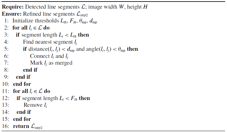
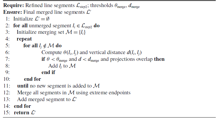
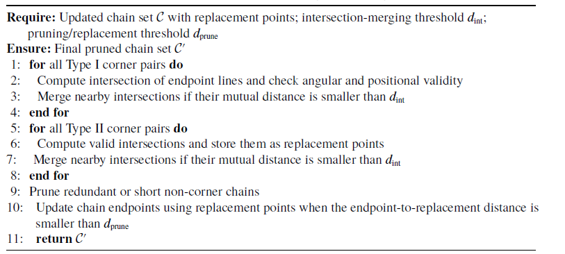
After resolution-aware preprocessing, most texture-induced interference is suppressed while the major fabric-supporting line segments are preserved. However, the remaining detections may still contain short, disordered, or partially redundant segments, especially near towel boundaries and local folds, as shown in Figure 3(a). To recover more stable boundary-supporting structures, a repair-filter-merge strategy is adopted. This stage first reconnects potentially useful short collinear fragments, then removes uninformative short segments, and finally merges overlapping or nearly parallel segments to improve structural continuity, and the detailed procedure is summarized in Appendix B1 (Algorithm 1) and Appendix B2 (Algorithm 2).
For each line segment, its length
 $L$
is computed from endpoints. Segments shorter than a threshold
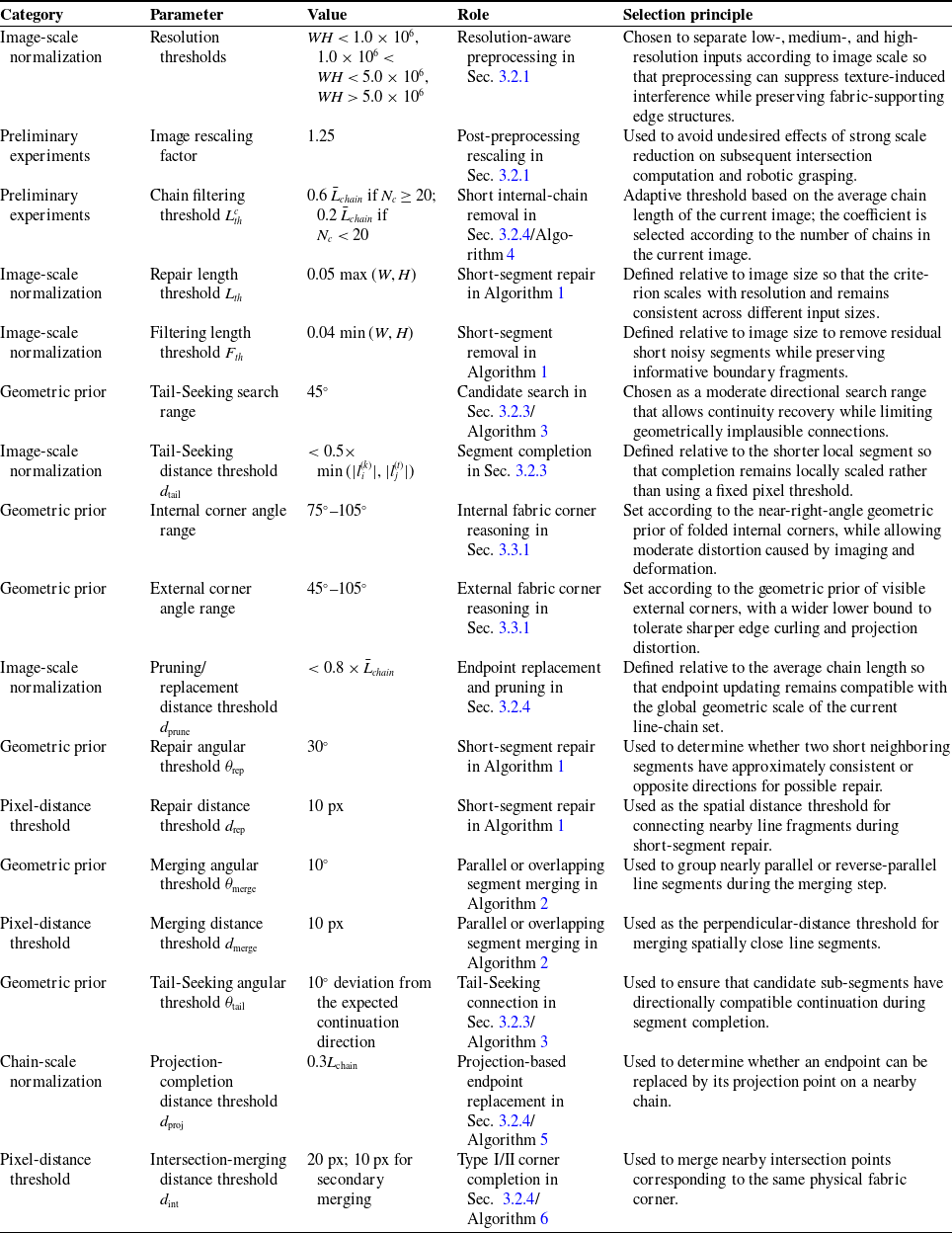
 $L_{th}=0.05\max (W,H)$
are considered for repair. The angle
 $\theta$
between a short segment and its nearest neighbor is calculated as:
 \begin{equation} \theta = \arccos \frac {(x_1-x_2)(x_3-x_4)+(y_1-y_2)(y_3-y_4)}{\sqrt {(x_1-x_2)^2+(y_1-y_2)^2}\cdot \sqrt {(x_3-x_4)^2+(y_3-y_4)^2}} \end{equation}
Short segments that are nearly collinear and close in distance are connected. Remaining segments shorter than
 $F_{th}=0.04\min (W,H)$
are filtered out.
For overlapping or parallel segments (Figure 3(c)), a merging process iteratively groups segments with small angles and distances, merging them into a single segment using the extreme endpoints. After repair, filtering, and merging, the resulting segments outline the towel contour, remove noise, and locate towel corners (Figure 3(d)), providing a solid basis for subsequent morphological analysis.
3.2.3. Segment completion and chain construction
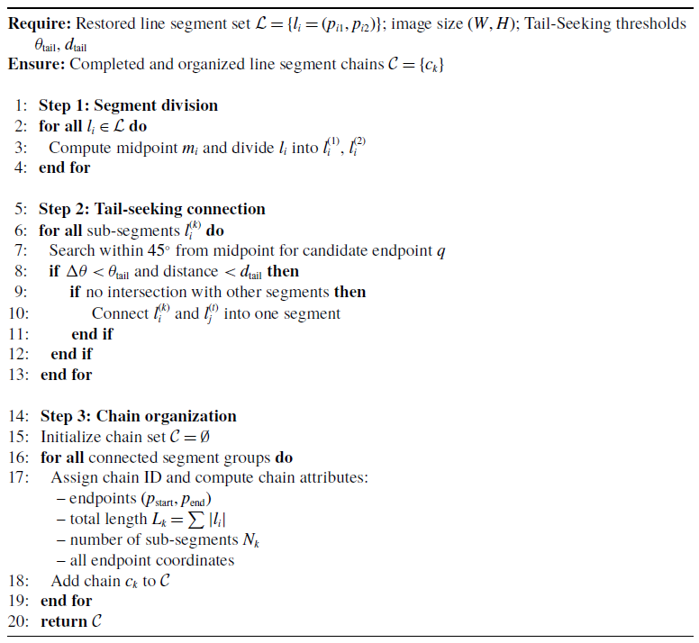
Although the repaired and merged line segments already provide a cleaner geometric description, some fabric-supporting edge structures may still remain partially disconnected. Directly computing intersections from these incomplete structures would produce many invalid corner candidates. To further improve boundary continuity and prepare for chain-level reasoning, a Tail-Seeking strategy is introduced to complete disconnected segment fragments and organize them into line segment chains, the detailed procedure is summarized in Appendix B3 (Algorithm 3).
As shown in Figure 3(e), each restored line segment is first split at its midpoint into two directional sub-segments before the completion step. This segment-splitting operation makes the subsequent Tail-Seeking process more explicit because each sub-segment can independently search for a compatible neighboring endpoint along its extending direction. The key idea is to transform isolated segment fragments into topologically organized structures while preserving their original geometric orientation.
Illustration of the LS-CDCT structural recovery process. (a) Raw line detections after preprocessing. (b) Restoration of short but useful boundary fragments. (c) Filtering of residual short noisy segments. (d) Merging of overlapping or nearly parallel segments. (e) Splitting of each restored segment into two directional sub-segments for Tail-Seeking. (f) Completion of previously unconnected segment fragments into more continuous edge-supporting structures. Red circles and zoom-in views highlight representative local regions during the refinement process.

Figure 3. Long description
This figure shows the line segment refinement process. Subfigure (a) shows raw detections after preprocessing; (b) shows restoration of useful short boundary fragments; (c) shows removal of short noisy segments; (d) shows merging of overlapping or nearly parallel segments; (e) shows splitting each restored segment into directional sub-segments; and (f) shows completion of disconnected fragments into more continuous edge-supporting structures. Red circles and zoom-in views indicate representative local changes.
Each line segment
 $l_i=(p_{i1},p_{i2})$
is first divided at its midpoint
 $m_i=\frac {p_{i1}+p_{i2}}{2}$
into two sub-segments, denoted as
 $l_i^{(1)}=(m_i,p_{i1})$
and
 $l_i^{(2)}=(m_i,p_{i2})$
, as illustrated in Figure 3(e). For each sub-segment, a search is then performed within a
 $45^\circ$
range from
 $m_i$
toward its endpoint
 $p_e$
to find a candidate endpoint
 $q$
belonging to another segment
 $l_j^{(t)}$
. A candidate is accepted if it satisfies both the Tail-Seeking angular and distance constraints:
 \begin{equation} \Delta \theta (l_i^{(k)}, l_j^{(t)}) \lt \theta _{\mathrm{tail}}, \quad \mathrm{dist}(p_e, q) \lt d_{\mathrm{tail}}, \end{equation}
where
 $\Delta \theta (l_i^{(k)}, l_j^{(t)})$
denotes the angular deviation from the expected continuation direction, and
 $\theta _{\mathrm{tail}}$
and
 $d_{\mathrm{tail}}$
are the Tail-Seeking angular and distance thresholds listed in Appendix Table A1, respectively. Once such a pair is found, the two sub-segments are connected to form a continuous edge, as illustrated in Figure 3(f).
During this process, the original geometric orientation of the detected line segments is preserved, while continuity along fabric-supporting edges is explicitly enhanced. To manage the recovered structures efficiently, we define a line segment chain as a topologically connected group of original and completed segments. Chain construction provides a higher-level structural representation than individual line segments, which is more suitable for subsequent corner reasoning.
The geometric attributes stored for each line segment chain include:
-
• Line segment chain ID: a unique identifier for each line segment chain in the image;
-
• Line segment chain endpoints: the coordinates of the start and endpoints of the current line segment chain;
-
• Line segments at chain endpoints: the endpoint information of the sub-segments at the start and endpoints of the line segment chain;
-
• Total chain length: the sum of the lengths of all sub-segments that make up the line segment chain;
-
• Number of internal segments: the number of sub-segments that make up the line segment chain;
-
• All line segments in the chain: the endpoint information of all sub-segments within the line segment chain.
Illustration of edge/internal chain filtering. (a) Local endpoint analysis of two line segment chains, where red indicates the presence of nonzero pixels in the corresponding direction and green indicates the absence of nonzero pixels. (b) Edge/internal classification results for the same local example. (c) Filtering result of the corresponding local line segment chains after applying the edge/internal chain decision.

Figure 4. Long description
This figure explains how line segment chains are classified as edge chains or internal chains. Subfigure (a) shows local endpoint analysis, where red indicates directions with non-zero pixels and green indicates directions without non-zero pixels. Subfigure (b) shows the resulting edge/internal chain classification. Subfigure (c) shows the filtered line-chain result after preserving edge chains and removing short internal chains.
3.2.4. Edge/internal chain filtering and corner completion
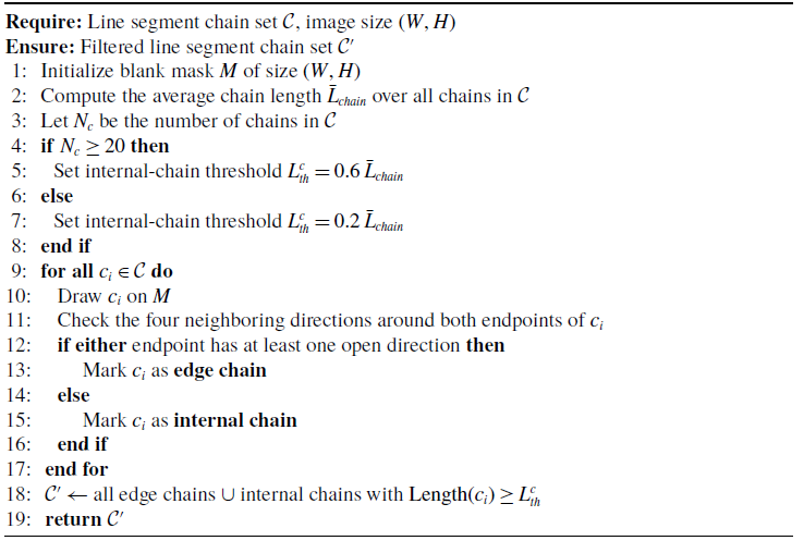
After chain construction, several short internal chains may still remain and interfere with corner localization. To suppress these disturbances while preserving fabric contour continuity, an edge/internal chain filtering strategy is introduced. The key idea is that edge chains are more likely to support visible fabric boundaries, whereas short internal chains are more likely to correspond to local texture, wrinkles, or incomplete fold structures.
Each chain is rasterized on a blank mask image, and the nonzero occupancy around its two endpoints is examined in the four neighboring directions (up, down, left, and right). If at least one neighboring direction around either endpoint does not contain nonzero pixels on the rasterized mask, the chain is classified as an edge chain; otherwise, it is classified as an internal chain. Let
 $L_k$
denote the total length of chain
 $c_k$
, and let
 $\bar {L}_{chain}$
denote the average length of all chains in the current image. Instead of using a fixed absolute pixel threshold, the short-chain removal criterion is adaptively defined with respect to the current chain statistics:
 \begin{equation} L_k \ge \begin{cases} 0.6\,\bar {L}_{chain}, & N_c \ge 20,\\[2mm] 0.2\,\bar {L}_{chain}, & N_c \lt 20, \end{cases} \end{equation}
where
 $N_c$
is the number of chains in the current image. All edge chains are retained directly, whereas only internal chains satisfying the above condition are preserved. In this way, the filtering threshold is not explicitly tied to a fixed image-size coefficient but is adaptively determined by the chain-length distribution of the current image. The principle and result of this filtering process are illustrated in Figure 4, and the detailed procedure is summarized in Appendix B4 (Algorithm 4).
Illustration of corner completion and pruning. Stage 1 shows the classification of two types of candidate corners, where red circles indicate Type I corners and green circles indicate Type II corners. Stage 2 shows the corresponding processing results for the two corner types. Stage 3 shows the final results after pruning and filtering.

Figure 5. Long description
This figure presents the corner completion process in three stages. Stage 1 classifies two types of candidate corners: Type I corners, marked by red circles, where the closest distance occurs between two chain endpoints; and Type II corners, marked by green circles, where one endpoint projects onto another chain. Stage 2 shows the corresponding processing results for these two corner types. Stage 3 shows the final refined results after pruning and filtering redundant chain extensions.
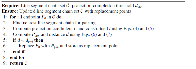
To further improve geometric continuity and corner localization at the chain level, a corner completion procedure is introduced to bridge gaps between adjacent line segment chains by detecting valid intersections and replacing incomplete endpoints. This completion step explicitly handles two common geometric gap patterns observed around fabric corners and folded boundaries. Two geometric cases are considered, as illustrated in Figure 5(I): (1) Type I corners, where the closest distance occurs between two chain endpoints (Figure 5(I-a)), and (2) Type II corners, where one endpoint projects perpendicularly onto another chain (Figure 5(I-b)).
For the latter case, the projection coefficient
 $t$
is introduced to determine whether the projection point lies within the segment. Let the current point be
 $P_0(x_0,y_0)$
, and the two endpoints of another line segment chain be
 $P_1(x_1,y_1)$
and
 $P_2(x_2,y_2)$
. The projection computation is expressed as:
 \begin{equation} t' = \frac {\boldsymbol{P} \cdot \boldsymbol{L}}{|\boldsymbol{L}|^2} \end{equation}
where
 $\boldsymbol{P}=(x_0-x_1,\,y_0-y_1)$
is the vector from
 $P_1$
to
 $P_0$
, and
 $\boldsymbol{L}=(x_2-x_1,\,y_2-y_1)$
is the vector along the target line segment.
The projection coefficient
 $t$
is constrained within the range
 $[0,1]$
:
 \begin{equation} t = \max (0, \min (1, t')) \end{equation}
The coordinates of the projection point and the corresponding distance are then computed as:
 \begin{align} \boldsymbol{P_{proj}} = (x_1 + t(x_2 - x_1),\, y_1 + t(y_2 - y_1)) \\[-6pt] \nonumber \end{align}
 \begin{align} \text{Distance} = \sqrt {(x_0 - x_{proj})^2 + (y_0 - y_{proj})^2} \\[12pt] \nonumber \end{align}
If the projection point lies outside the segment (
 $t=0$
or
 $t=1$
), the distance to the nearest endpoint is used instead. Otherwise, the distance between
 $P_0$
and
 $P_{proj}$
determines the degree of geometric continuity. When this distance is smaller than the projection-completion threshold
 $d_{\mathrm{proj}}$
,
 $P_0$
is replaced by
 $P_{\mathrm{proj}}$
to complete the edge connection. The value of
 $d_{\mathrm{proj}}$
is listed in Appendix Table A1. The projection and replacement procedure is summarized in Appendix B5 (Algorithm 5).
Subsequently, Type I corner pairs are processed to compute intersection points between the extended lines of adjacent segment chains, and those satisfying angular and positional constraints are retained. If multiple intersection points from different chain pairs are close to each other, namely within the intersection-merging threshold
 $d_{\mathrm{int}}$
, they are merged to restore the actual edge continuity, as indicated by the red regions in Figure 5 (Stage 2). The value of
 $d_{\mathrm{int}}$
is listed in Appendix Table A1.
For Type II corners, valid projection-based intersection points are stored as “replacement points” in the chain data structure to support endpoint substitution and pruning. The corresponding completion segments are also recorded for subsequent refinement. The green-marked regions in Figure 5 (Stage 2) show the results of this process.
However, some redundant extensions may remain at chain ends due to intersections located inside the segment. To address this, a pruning algorithm is introduced to remove superfluous parts. Specifically, endpoints that appear only once and are close to their replacement points, according to the pruning/replacement distance threshold
 $d_{\mathrm{prune}}$
, are replaced and updated, yielding the final refined line segment chain collection, as shown in Figure 5 (Stage 3). The overall Type I/II corner handling and pruning procedures are summarized in Appendix B6 (Algorithm 6).
Figure 5 summarizes this procedure in three stages: Stage 1 shows the classification of Type I and Type II candidate corners, Stage 2 shows the corresponding intermediate processing results, and Stage 3 shows the final refined results after pruning and filtering.
After these steps, LS-CDCT outputs a refined set of line segment chains with improved continuity, reduced local disorder, and more reliable corner-supporting geometry, which directly supports the fabric corner reasoning stage described in the next subsection.
3.3. Geometric fabric corner reasoning
Based on the refined line segment chains produced by LS-CDCT, the next step is to identify real fabric corners from geometrically plausible chain intersections. Rather than directly treating all intersections as candidate grasping points, we formulate fabric corner recognition as a geometric reasoning problem under fabric-specific structural priors. This design is motivated by the observation that many intersections produced by wrinkles, shadows, folds, or incomplete boundaries do not correspond to true graspable fabric corners.
3.3.1. Geometric priors for visible fabric corners
Building on prior analyses of fabric corner categories [Reference Lin, Wang, Olkin and Held15], this work adopts a lightweight reasoning strategy using only the line segment chain information recovered in the previous subsection. For visible fabric corners, we use the following prior knowledge:
-
(i) Fabric corners can generally be divided into internal fabric corners (usually referring to corners folded inward into the fabric) and external fabric corners (where the corner point lies on the fabric edge). Considering image distortion or environmental influences, the angle of internal fabric corners is set between 75
 $^\circ$
and 105
$^\circ$
, as shown in Figure 6(a); the angle of external fabric corners is set between 45
$^\circ$
and 105
$^\circ$
(external fabric corners are more likely to exhibit edge curling, with the corner appearing sharp), as shown in Figure 6(b);
-
(ii) External fabric corners typically present a convex shape relative to the fabric center, as shown in Figure 6(c);
-
(iii) Internal fabric corners, due to the folding process, form a triangular shape with the crease line on both sides of the corners, as indicated by the triangle annotation in Figure 6(a) (where the yellow line represents the fabric corner edge, and the blue line represents the crease);
-
(iv) Fabric corner points are formed by the intersection of two edges. If a certain intersection point is not formed by only two line segments, or if the intersection lies within a line segment and forms a “y” shape with another line segment, it is considered not to be a fabric corner point, as shown in Figure 6(d).


3.3.2. Candidate corner generation and intersection filtering
Based on the above priors, fabric corner recognition is performed using the chain-level geometric information recovered by LS-CDCT. The goal of this stage is to progressively reject invalid intersections and retain only those that are structurally consistent with real visible fabric corners. First, the endpoint set of the refined line segment chains is processed by convex hull analysis, and the centroid of the resulting convex hull is defined as the fabric center. This fabric center serves as a global geometric reference point for subsequent convexity/concavity reasoning of candidate corner intersections. It should be noted that the fabric center here does not refer to the image center, but to the centroid of the convex hull formed by the endpoints of the refined line segment chains. If no valid fabric corner is detected, the centroid coordinates are returned for subsequent robotic repositioning or state adjustment.
Some fabric corners (green circles) and non-fabric corners (red circles).

Figure 6. Long description
This figure shows representative cases for fabric corner reasoning. Green circles indicate valid fabric corners, including internal and external corners. Red circles indicate non-fabric corners caused by folds, invalid intersections, or Y-shaped line structures. The examples illustrate the geometric priors used to distinguish real visible fabric corners from false corner-like structures.
Real visible fabric corners are expected to appear at intersections formed by processed line segment chains and, more specifically, within the set of chain endpoints. According to prior knowledge (iv), valid fabric corners should be formed by exactly two boundary-supporting structures. Therefore, within the set of line segment chain endpoints, we first identify those endpoints that appear exactly twice, indicating that one endpoint of the current chain coincides with only one endpoint of another chain. This step excludes cases in which an endpoint lies inside another segment or where three or more line structures converge at the same point.
For the filtered candidate endpoints, the corresponding intersection coordinates are computed together with the angle formed by the two supporting line segments. These intersections are then partitioned into edge intersections and non-edge intersections. The criterion for identifying an edge intersection is whether at least one of the four neighboring directions around the intersection does not contain nonzero pixels. If such a direction exists, the point is classified as an edge intersection; otherwise, it is treated as a non-edge intersection. According to prior knowledge (i), external fabric corners are selected from edge intersections, whereas internal fabric corners are selected from non-edge intersections. These filtered intersections are then passed to the subsequent external and internal corner reasoning stage.
Special selection of internal and external corner points. I shows the convexity/concavity analysis of external fabric corners (point 1 represents a concave state, point 2 represents a convex state). The point labeled as center denotes the fabric center, defined as the centroid of the convex hull formed by the endpoints of the refined line segment chains. II shows the crease existence analysis for internal fabric corners.

Figure 7. Long description
This figure shows two special reasoning steps for fabric corner selection. Part I illustrates convexity and concavity analysis for external fabric corners, where point1 represents a concave state and point2 represents a convex state relative to the fabric center. Part II illustrates crease existence analysis for internal fabric corners, where additional line structures along the bisector direction support the identification of folded internal corners.
3.3.3. External and internal corner reasoning
For external fabric corners, a convexity-based reasoning step is further applied to the edge intersections, following prior knowledge (ii). Specifically, we compute the geometric relationship between the convex hull centroid and each processed edge intersection, together with the angles formed by the two supporting line segments. Intersections in a convex state typically exhibit at least one sharp angle between the two sides, as illustrated by the green region in Figure 7(I), whereas concave intersections usually show obtuse local geometry, as illustrated by the red region. Only intersections consistent with the convex-state assumption are retained as candidates for external fabric corners.
For internal fabric corners, angle constraints alone are insufficient because internal folds may be partially occluded or visually ambiguous. Therefore, in addition to angular screening, a crease-consistency analysis is introduced according to prior knowledge (iii). In towels and similar fabrics, internal corners are often accompanied by fold-related line structures on both sides of the corner. Since the complete triangular folding pattern may not always be fully visible in practice, we adopt a simplified criterion and examine whether additional line structures exist along the bisector direction of the candidate corner. This strategy preserves the structural meaning of internal corners while remaining tolerant to partial occlusion and incomplete fold visibility, as illustrated in Figure 7(II-a). It also helps recover internal corners that may be missed during edge-intersection selection, such as those formed by nearly horizontal or vertical supporting segments, as shown in Figure 7(II-b).
3.3.4. Bisector extraction for grasp orientation
For each selected internal or external corner candidate, the bisector direction is further extracted to characterize the local corner geometry and provide a grasp-orientation reference for the robotic gripper. Let the selected corner point be
 $P^*=(x^*,y^*)$
, and let the two non-shared endpoints of the supporting line segments be
 $P_1=(x_1,y_1)$
and
 $P_2=(x_2,y_2)$
. Then the two line segments incident to the corner are denoted as
 $\boldsymbol{S_1}=(P^*,P_1)$
and
 $\boldsymbol{S_2}=(P^*,P_2)$
. Their direction vectors are given by Eq. (8):
 \begin{equation} \boldsymbol{v_1}=P_1-P^*, \boldsymbol{v_2}=P_2-P^* \end{equation}
Next, calculate the unit vectors of the two line segment direction vectors as Eq. (9):
 \begin{equation} \boldsymbol{\hat {v}_1}=\frac {\boldsymbol{v_1}}{\left | v_1 \right | } = \left(\frac {x_1-x^*}{\left | v_1 \right |}, \frac {y_1-y^*}{\left | v_1 \right |}\right), \boldsymbol{\hat {v}_2}=\frac {\boldsymbol{v_2}}{\left | v_2 \right | } =\left(\frac {x_2-x^*}{\left | v_2 \right |}, \frac {y_2-y^*}{\left | v_2 \right |}\right) \end{equation}
where
 $\left | v_1 \right |$
and
 $\left | v_2 \right |$
are the magnitudes of the vectors, and the direction vector of the bisector can be obtained as Eq. (10):
 \begin{equation} \boldsymbol{\hat {v}_{bisector}}=\boldsymbol{\hat {v}_1}+\boldsymbol{\hat {v}_2} \end{equation}
The angle from the horizontal
 $x-axis$
to the direction of the bisector can be calculated using the arctangent function
 $atan2(y,x)$
as Eq. (11):
 \begin{equation} \theta _{bisector}=atan2(\boldsymbol{\hat {v}_{bisector,y} },\boldsymbol{\hat {v}_{bisector,x} }) \end{equation}
where
 $\boldsymbol{\hat {v}_{bisector,x}}$
and
 $\boldsymbol{\hat {v}_{bisector,y}}$
denote the
 $x$
- and
 $y$
-components of the bisector direction vector, respectively.
Figure 8 shows representative corner detection results obtained by applying the proposed chain-based geometric reasoning procedure to the refined line representations recovered by LS-CDCT.
Corner detection results for images with different resolution sizes.

Figure 8. Long description
This figure presents several examples of final fabric corner detection results after applying chain-based geometric reasoning to the refined line segment representations. The examples include fabric images with different resolutions and show detected corner locations and bisector directions used for subsequent robotic grasping.
3.4. Corner-to-grasp mapping and robotic execution
Based on the detected fabric corners and their bisector orientations, the final step of the proposed framework is to convert the corner perception results into executable robotic grasping actions. To this end, we employ a single six-axis robotic arm with an eye-in-hand camera configuration to capture the target fabric and perform corner-guided grasping on a tabletop platform.
During image acquisition, the robotic arm carries the camera to a designated observation pose, and the height
 $d$
between the camera and the fabric placement platform can be calculated from the robot pose and the camera mounting parameters. Since the fabric is easily deformed under external forces, its corners may rise, fold, or locally collapse, resulting in uncertain height variation. For thin and deformable fabrics, such local height changes are difficult to estimate accurately using ordinary depth sensing. Therefore, rather than assuming precise corner depth, we adopt a feedback-guided top-down grasping strategy to tolerate depth uncertainty during execution.
Specifically, let
 $d$
denote the height from the camera to the fabric placement platform. To avoid relying on an accurate estimate of the local fabric-corner depth, we introduce a platform-clearance offset
 $\delta$
, which denotes the vertical distance between the grasping plane and the platform surface. Considering that the fabric thickness is less than 3 mm and may increase to nearly 9 mm when naturally folded into multiple layers, the initial clearance offset is set to
 $\delta _0=15\,\mathrm{mm}$
. Therefore, the initial grasping plane is located 15 mm above the platform, and the corresponding vertical coordinate used for coordinate transformation is given by
 \begin{equation} z_0=d-\delta _0=d-15\,\mathrm{mm}. \end{equation}
Once the fabric corner coordinates and the associated grasping angle are obtained from the corner reasoning stage, the robot aligns the gripper orientation with the bisector direction of the selected corner and starts the first grasping attempt at the initial grasping plane. After each attempt, the gripper feedback signal is used to determine whether the grasping action has been successful. If the grasp fails at the
 $k$
-th attempt, the clearance offset is reduced by a fixed step
 $\Delta \delta =3\,\mathrm{mm}$
, and the next grasping plane is updated as:
 \begin{equation} \delta _{k+1}=\delta _k-\Delta \delta ,\qquad z_{k+1}=d-\delta _{k+1}. \end{equation}
Equivalently, the robot moves the gripper downward by 3 mm toward the platform after each failed attempt. This feedback-guided top-down adjustment continues until the fabric corner is successfully grasped and lifted.
For grasp point selection, priority is given to the external fabric corner closest to the current robot end position. If no valid internal or external fabric corner is detected, the centroid of the fabric is used as the fallback grasp point. Figure 9 illustrates the overall robotic setup and the corresponding corner-to-grasp execution procedure, with the lower part redrawn as a standard flowchart for clarity.
System overview and standard flowchart of the corner-to-grasp execution procedure. The upper part shows the robotic fabric corner recognition and grasping setup, and the lower part shows the feedback-guided execution workflow. In the flowchart,
 $d$
denotes the camera-to-platform height,
 $\delta$
denotes the clearance offset above the platform, and
 $z=d-\delta$
denotes the grasping plane used for coordinate transformation.

Figure 9. Long description
The upper part shows the robotic setup, including the industrial computer, robotic arm, eye-in-hand camera, gripper with feedback signal, platform, and target fabric. The lower part shows the execution workflow. The robot first reaches the image capture position, detects fabric corners, and calculates either the target corner point or the fabric centroid if no valid corner is detected. The gripper then moves to the grasping plane. If grasping fails, the clearance offset is reduced by 3 mm and the grasping plane is updated until the fabric corner is successfully grasped and lifted.
4. Experimental evaluation
This section evaluates the proposed framework from four aspects: visible fabric corner recognition performance, quantitative comparison with traditional geometry-based baselines and detector-replacement variants, robotic grasping validation, and supplementary capability-limit evaluation on non-rectangular fabrics.
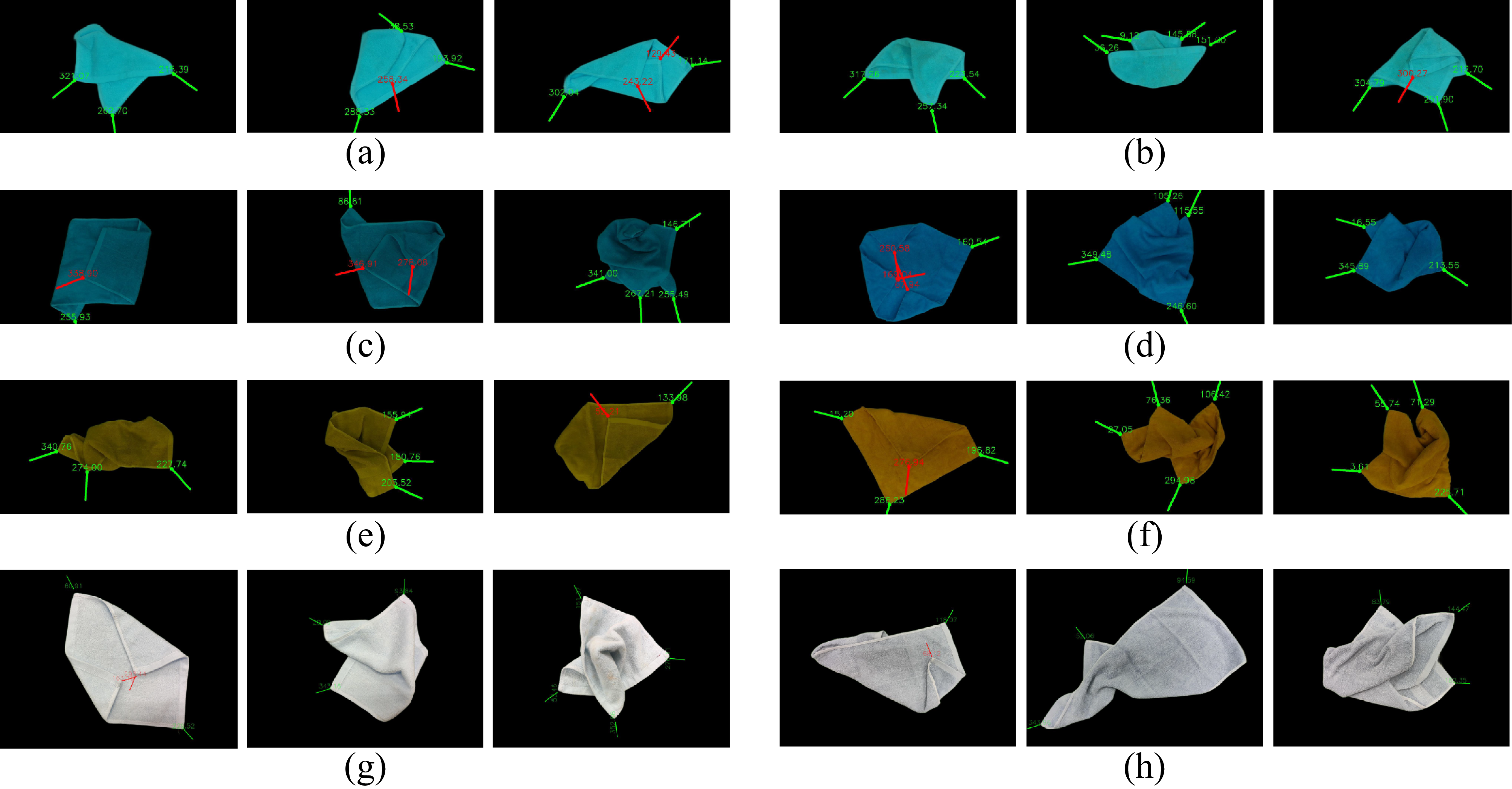
Partial fabric sample images. In the figure, (a), (b), and (g) show images of 27 cm
 $\times$
27 cm towels in different colors under various conditions; (d) and (f) show images of 50 cm
 $\times$
50 cm towels in different colors under various conditions; (c), (e), and (h) show images of 70 cm
 $\times$
32 cm towels in different colors under various conditions.

Figure 10. Long description
This figure shows partial fabric sample images used in the experiments. The examples include towels with different colors, sizes, and random configurations. The samples cover small and medium-sized fabrics, including square and rectangular towels, under various folded, wrinkled, and partially occluded states.
4.1. Experimental setup and fabric dataset
To evaluate the proposed LSD-enhanced line perception, structural recovery, and geometric corner reasoning framework, experiments were conducted on a fabric image dataset collected under constrained tabletop conditions. The fabric images were captured using monocular RGB cameras and were used to evaluate visible fabric corner recognition under variations in fabric size, color, posture, lighting, and image resolution. Representative fabric samples are shown in Figure 10.
Fabric objects: Due to the limitations of the perception conditions, this paper mainly focuses on detection experiments for common light-colored, solid-colored medium and small towels. The selected samples include various common sizes such as 27 cm
 $\times$
27 cm, 50cm
 $\times$
50 cm, 70 cm
 $\times$
32 cm, and common colors like blue, yellow, gray, light blue, and gray-white.
Fabric postures: We randomly configure the fabric as much as possible, including fully unfolded states (where all fabric corners are visible), partially occluded fabric corners, and varying degrees of wrinkling. The configuration methods include manually placing the fabric into specific postures and allowing it to fall freely to obtain different postures.
Representative fabric corner recognition results on the collected dataset. Green annotations indicate external fabric corners, and red annotations indicate internal fabric corners. The short line drawn at each detected corner denotes the corresponding corner bisector direction, which is further used as the mapped grasping direction in robotic execution. Subfigures (a) and (b) show results for low-resolution small fabrics; (c)–(f) show results for low-resolution medium-sized fabrics with different colors; (g) shows results for a high-resolution small fabric; and (h) shows results for a high-resolution medium-sized fabric. A legend is included in the figure for clarity.

Figure 11. Long description
This figure shows recognition examples from the collected fabric dataset. Green annotations indicate detected external fabric corners, and red annotations indicate detected internal fabric corners. The short line at each detected corner denotes the corresponding bisector direction, which is used as the mapped grasping direction during robotic execution. The examples cover low-resolution and high-resolution images, different fabric sizes, and different fabric colors.
Background setting: As mentioned at the beginning of the article, considering that in operational scenarios such as industrial production, the workbench surface is often of a single color with no other distracting objects, we place the fabric on a solid-colored platform and perform background removal on the obtained images, focusing solely on the fabric itself.
Lighting conditions: Based on the detection principle, when detecting fabric corners in a 2D image, for fabrics with obvious edge features (such as thickened edges, wide seams, or a significant color contrast between the fabric edge and the main body), the detection of internal fabric corners relies more on the shadow information at the fabric edges. Therefore, in terms of lighting selection, we avoid using light sources with excessive intensity. Instead, we place the light source above the fabric placement platform and set three levels of brightness: dim light, normal light close to natural light, and bright light.
Image acquisition: The main method for acquiring images is by using the monocular RGB function of the RealSense D435i camera, capturing images with resolutions such as 1920
 $\times$
1080 and 1280
 $\times$
720. Additionally, images are also captured using a mobile phone camera at a resolution of 4096
 $\times$
3072, allowing the algorithm to process input images of different resolutions.
Based on the above settings, a total of 160 fabric images were collected under different lighting conditions, fabric configurations, colors, sizes, and image resolutions. Among them, 489 visible fabric corners were annotated, including 428 visible external corners and 61 visible internal corners.
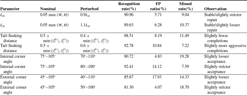
For reproducibility, the main parameter settings used in the proposed framework are summarized in Appendix Table A1. In addition, a compact one-at-a-time robustness verification for representative parameters is provided in Appendix Table A2.
4.2. Fabric corner recognition performance
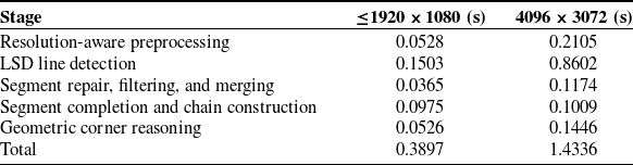
The proposed corner recognition method was evaluated on the collected fabric dataset using an industrial control computer equipped with Intel(R) UHD Graphics 630 integrated graphics. For images with a resolution of 1920
 $\times$
1080 or lower, the average processing time was 0.3897 s, while for high-resolution images of 4096
 $\times$
3072, the average processing time was 1.4336 s. Representative recognition results on background-removed images are shown in Figure 11.
To provide a clearer runtime profile, the average processing time was further broken down into the main stages of the proposed pipeline, namely resolution-aware preprocessing, LSD line detection, segment repair/filtering/merging, segment completion and chain construction, and geometric corner reasoning, as summarized in Table I. The results show that LSD line detection is the dominant time-consuming stage in both cases, especially for high-resolution images, whereas the later geometric corner reasoning stage accounts for a relatively smaller portion of the total runtime.
Average time consumption of different stages in the detection pipeline.

Table I. Long description
A table comparing the average time consumption of different stages in a detection pipeline for two image resolutions. The table has six rows and five columns. The columns are labeled Stage, Resolution-aware preprocessing, LSD line detection, Segment repair, filtering, and merging, Segment completion and chain construction, and Geometric corner reasoning. The rows are labeled with the stages of the pipeline and the time consumption in seconds for two different resolutions: less than or equal to 1920 x 1080 and 4096 x 3072. Row 1: Resolution-aware preprocessing, 0.0528, 0.2105. Row 2: LSD line detection, 0.1503, 0.8602. Row 3: Segment repair, filtering, and merging, 0.0365, 0.1174. Row 4: Segment completion and chain construction, 0.0975, 0.1009. Row 5: Geometric corner reasoning, 0.0526, 0.1446. Row 6: Total, 0.3897, 1.4336.
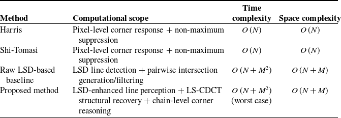
In addition to the empirical runtime reported above, we provide a compact theoretical complexity comparison. It should be noted that the compared methods are not fully equivalent in function. Harris and Shi-Tomasi are classical pixel-level corner detectors, while raw LSD is a line segment detector. In contrast, the proposed method is not merely a detector, but a task-oriented framework built on top of LSD, including LS-CDCT-based structural recovery, chain-level corner reasoning, and grasp-oriented geometric filtering. Therefore, the following comparison is intended as a compact computational reference rather than a claim of strict functional equivalence among all methods.
Let
 $N$
denote the number of image pixels,
 $M$
the number of detected line segments, and
 $K$
the number of refined line segment chains, where
 $K \leq M$
. Classical pixel-level corner detectors such as Harris and Shi-Tomasi mainly operate on image gradients and local response maps and therefore have
 $O\,(N)$
time complexity and
 $O\,(N)$
space complexity. The raw LSD-based baseline requires
 $O\,(N)$
line extraction together with pairwise intersection generation and filtering, which leads to a worst-case complexity of
 $O\,(N+M^2)$
and a space complexity of
 $O\,(N+M)$
. The proposed framework retains the
 $O\,(N)$
image-level front-end, while LS-CDCT-based structural recovery and chain-level corner reasoning involve pairwise segment/chain checks in the worst case. Since
 $K \leq M$
, the corresponding chain-level reasoning is absorbed into the worst-case term
 $O(M^2)$
. As a result, the proposed method has an overall worst-case time complexity of
 $O\,(N+M^2)$
and a space complexity of
 $O\,(N+M)$
. A summary is provided in Table II.
Compact theoretical time and space complexity comparison.

Table II. Long description
A table comparing computational methods and their complexities. The table has four rows and four columns. The columns are labeled Method, Computational scope, Time complexity, and Space complexity. The rows are labeled Harris, Shi-Tomasi, Raw LSD-based baseline, and Proposed method. Each row provides details on the computational scope, time complexity, and space complexity for each method. For example, the Harris method has a computational scope of Pixel-level corner response + non-maximum suppression, a time complexity of O(N), and a space complexity of O(N). The Shi-Tomasi method has similar complexities. The Raw LSD-based baseline method has a computational scope of LSD line detection + pairwise intersection generation/filtering, a time complexity of O(N + M^2), and a space complexity of O(N + M). The Proposed method has a computational scope of LSD-enhanced line perception + LS-CDCT structural recovery + chain-level corner reasoning, a time complexity of O(N + M^2), and a space complexity of O(N + M) in the worst case.
Therefore, the proposed method is asymptotically heavier than classical pixel-level detectors such as Harris and Shi-Tomasi, but it remains in the same worst-case complexity class as the raw LSD-based baseline, while providing more structured and task-relevant geometric reasoning for fabric corner recognition.
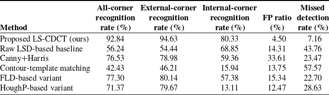
The recognition results were evaluated against manually annotated visible fabric corners using the point-matching protocol described in Section 4.3. Performance was analyzed for all visible fabric corners, as well as separately for external and internal fabric corners. The recognition rate, FP ratio, and missed detection rate were used as the main evaluation metrics. Here, the recognition rate measures the proportion of annotated visible fabric corners that are correctly detected, the FP ratio measures the number of unmatched detected corner points normalized by the number of annotated visible corners in the corresponding category, and the missed detection rate measures the proportion of annotated corners that are not detected. The results of the proposed method are summarized together with the baseline comparisons in Table III.
As shown in Table III, the proposed method performs reliably on the collected fabric dataset, with external fabric corners achieving a higher recognition rate than internal fabric corners. This is mainly because external corners usually present clearer boundary-supporting line structures, whereas internal corners are more easily affected by folds and shadows. In particular, the recognition rate for visible external fabric corners reaches 94.63%.
Quantitative comparison with traditional geometry-based baselines and detector-replacement variants.

Table III. Long description
A table comparing different corner recognition methods and their performance metrics. The table has 6 rows and 6 columns. The columns are labeled Method, All-corner recognition rate (percent), External-corner recognition rate (percent), Internal-corner recognition rate (percent), FP ratio (percent), and Missed detection rate (percent). The rows list different methods: Proposed LS-CDCT (ours), Raw LSD-based baseline, Canny+Harris, Contour-template matching, FLD-based variant, and HoughP-based variant. Each row provides the recognition rates, FP ratio, and missed detection rate for the respective method. Notable trends include the Proposed LS-CDCT method having the highest all-corner recognition rate at 92.84 percent and the Contour-template matching method having the lowest at 42.43 percent. The FP ratio and missed detection rate vary significantly across methods, with the Proposed LS-CDCT method showing a balanced performance across all metrics.
Examples of false positives or missed detections.

Figure 12. Long description
This figure illustrates typical recognition errors. Some missed detections occur when fabric corners are distorted by folding, lifting, or imaging perspective and no longer appear as clear right-angle structures. False positives may occur when wrinkles, shadows, or overlapping fabric edges form pseudo-corner structures that resemble true fabric corners.
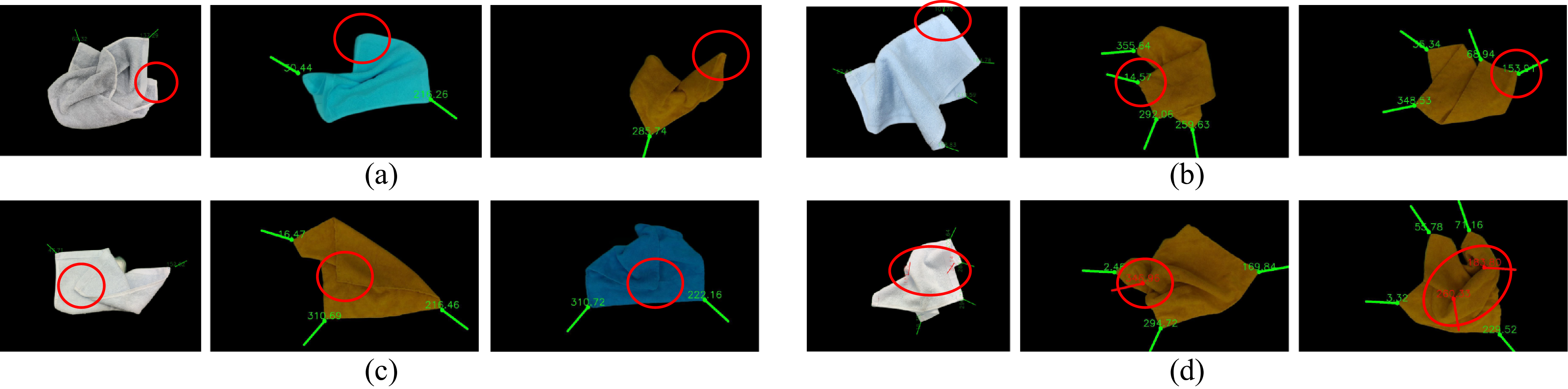
To better understand the remaining errors, we further analyze the main causes of false positives and missed detections for external and internal fabric corners. For external fabric corners, the main reason for missed detection is the diversity of fabric configurations, such as random folding, lifting, and other conditions, combined with distortion caused by the shooting angle or during the capturing process, which results in the fabric corner not appearing as a right angle in the 2D image (as shown in Figure 12(a)). To address these situations, we adopted a discarding strategy to reduce false detections. The main reason for false detection of external fabric corners is caused by fabric folds, as shown in Figure 12(b). When fabric edges overlap due to folding, or when the upper layer of fabric covers the lower layer, some parts of the crease may resemble a fabric corner, leading the fabric corner detection algorithm to mistakenly identify it as a corner, thus causing a false positive.
For internal fabric corners, the main reason for missed detection is the lack of distinct fabric edge features, especially under strong lighting conditions where the fabric corners within the fabric are difficult to reveal with clear contour features (as shown in Figure 12(c)). This results in the line segment detection failing to capture the edges of the fabric corners, leading to missed detections. The false detection of internal fabric corners is primarily caused by wrinkles or protrusions within the fabric and the shadows they form, as shown in Figure 12(d). If the shadow contours form a distinct and relatively regular triangular shape, the algorithm may mistakenly identify it as an internal fabric corner.
4.3. Comparison with baseline methods
Recent cloth corner or grasp-point detection studies include both learning-based and geometry-based approaches. Learning-based methods, such as cloth keypoint detectors or RGB-D-based manipulation systems, can improve perception robustness under diverse materials, patterns, backgrounds, and occlusion conditions, but they often require large-scale annotated data, additional sensing modalities, substantial computational resources, or more complex deployment pipelines. This work focuses on lightweight RGB-only perception and robotic execution in constrained tabletop industrial scenarios. Therefore, the quantitative comparison in this section is conducted with traditional geometry-based baselines and line-detector-replacement variants under the same RGB-based evaluation setting.
As the main geometry-based baseline, we use our earlier raw LSD-based fabric corner recognition method. In this baseline, background removal is first applied, after which raw LSD detections are directly used for corner candidate generation, without the LS-CDCT-based structural recovery and chain-level reasoning introduced in the present work. After removing short line segments, the algorithm computes the angles at the intersections of adjacent remaining segments and selects those satisfying the angular constraints as candidate fabric corner points. These candidates are then further filtered: intersection points outside the fabric convex hull, as well as those located on the line segment itself or its extensions, are removed. Clustering is further applied to regions with a high density of intersection points to suppress concentrations caused by wrinkles or shadows. In addition, intersection points formed by the convergence of multiple line segments are excluded to eliminate erroneous points caused by creases. Internal and external fabric corner candidates are then distinguished using similar geometric filtering principles wherever applicable.
To provide a broader quantitative comparison with traditional geometric methods, two additional conventional baselines were implemented. The first one is a Canny+Harris baseline. In this method, the background-removed RGB image is converted to grayscale and smoothed using Gaussian filtering. Canny edge detection is then applied to extract edge responses, and Harris corner response is computed within the fabric region. Non-maximum suppression and local clustering are used to remove duplicated responses, and candidate points outside the fabric mask are discarded. Since this baseline directly produces local corner responses rather than structured boundary-supported corners, it is used mainly as a point-localization baseline.
The second one is a contour-template matching baseline. After background removal, the largest fabric contour and its edge map are extracted, and a set of rotated and scaled corner templates is matched against local contour regions. The matched template vertices are then taken as candidate fabric corners. This baseline represents a traditional template-based geometric strategy. However, because the template shape is predefined, its performance is expected to be more sensitive to folding, occlusion, wrinkles, and non-rectangular local contour deformation.
To further examine the influence of the line-detection front-end, two detector-replacement variants are also considered by replacing the original LSD front-end with FLD and probabilistic Hough transform (HoughP), respectively, while keeping the subsequent geometric processing procedure unchanged. These variants are used to examine how the quality of front-end line detection affects the candidate line structures available to the overall framework.
All compared methods were evaluated on the same dataset of 160 fabric images containing 489 annotated visible fabric corners. The annotated corners were used only as reference points for offline evaluation and were not involved in the proposed corner recognition or robotic grasping pipeline. For fair evaluation across different image resolutions, each manually annotated visible fabric corner was allowed to match at most one detected point. A detected point was counted as a true positive (TP) if its Euclidean distance to an unmatched manually annotated visible corner was smaller than the image-size-normalized matching radius (
 $r=0.02\max (W,H)$
), which was used to account for minor annotation uncertainty and local fabric-corner localization ambiguity. If multiple detected points fell within the matching radius of the same annotated corner, only the closest one was counted as TP, and the remaining detections were counted as false positives (FP). Detected points without matched annotations were counted as FP, while annotated corners without matched detections were counted as false negatives (FN). The same matching rule and evaluation metrics were used for all compared methods.
The recognition rate, FP ratio, and missed detection rate were computed as:
 \begin{equation} R_{\mathrm{rec}}=\frac {TP}{N_{\mathrm{ann}}}\times 100\%, \quad R_{\mathrm{FP}}=\frac {FP}{N_{\mathrm{ann}}}\times 100\%, \quad R_{\mathrm{miss}}=\frac {FN}{N_{\mathrm{ann}}}\times 100\%. \end{equation}
The same matching rule and metric definitions were used for all compared methods, where (
 $N_{\mathrm{ann}}$
) denotes the number of annotated visible fabric corners in the corresponding category, and (
 $R_{\mathrm{rec}}$
), (
 $R_{\mathrm{FP}}$
), and (
 $R_{\mathrm{miss}}$
) denote the recognition rate, FP ratio, and missed detection rate, respectively.
For the proposed method, the raw counts were 454 TP, 22 FP, and 35 FN among all 489 annotated visible corners; 405 TP, 20 FP, and 23 FN for 428 external corners; and 49 TP, 2 FP, and 12 FN for 61 internal corners. The Wilson 95% confidence intervals for the recognition rates were 90.21–94.81% for all corners, 92.07–96.39% for external corners, and 68.69–88.37% for internal corners, indicating that the internal-corner result should be interpreted cautiously due to the smaller sample size. Since the proposed method is rule-based, all parameters were fixed before the final quantitative evaluation and applied consistently to all images without per-image adjustment.
The quantitative results are summarized in Table III. The Canny+Harris baseline can detect some visually salient corner-like responses, but it is easily affected by wrinkles, shadows, fragmented edges, and texture-induced responses. The contour-template matching baseline performs reasonably when the visible fabric contour is close to the predefined template shape, but its performance decreases when the fabric is folded, partially occluded, or strongly deformed. The detector-replacement results based on FLD and HoughP show that the choice of line detector influences the quality of low-level line candidates. Nevertheless, all these traditional baselines achieve lower recognition rates than the proposed method. This indicates that robust fabric-corner recognition depends not only on local edge, corner, or line responses but also on recovering boundary-supporting line structures and performing chain-level geometric reasoning. Under the same LSD front-end, the substantial improvement over the raw LSD-based baseline further demonstrates the contribution of the proposed LS-CDCT-based structural recovery and fabric-corner reasoning framework.
4.4. Robotic grasping evaluation with post-grasp reconfiguration
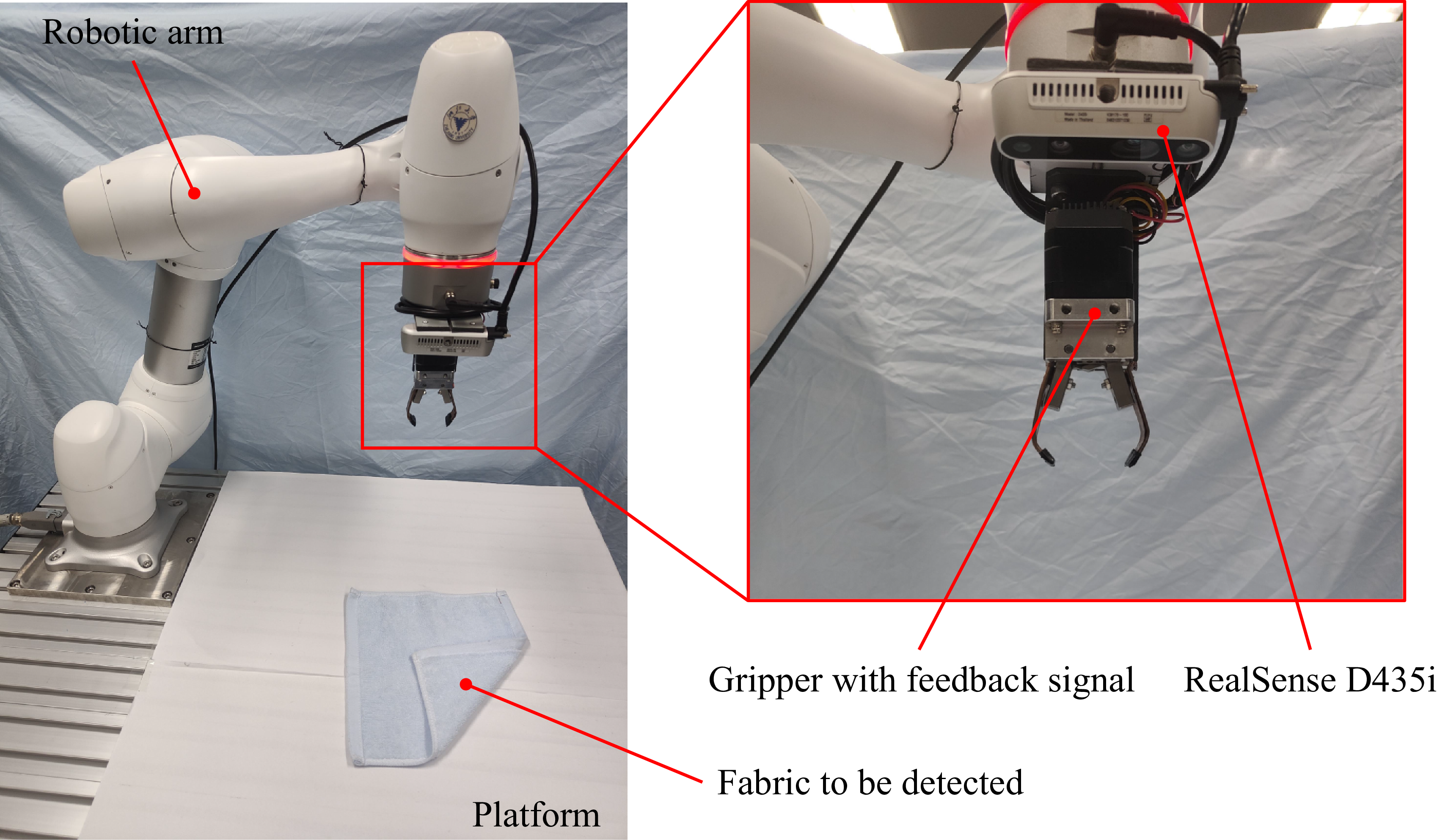
To verify that the detected fabric corners can be effectively translated into executable robotic actions, robotic grasping experiments were conducted using the corner-to-grasp pipeline proposed in this work. The experimental system is shown in Figure 13. A Doosan M0609 robotic arm was used for grasping, and a RealSense D435i camera with a resolution of 1280
 $\times$
720 was used for image acquisition. The system adopts an eye-in-hand configuration and a two-finger gripper equipped with grasping feedback signals.
Robot fabric corner recognition and grasping system.

Figure 13. Long description
This figure shows the physical robotic grasping system. A Doosan M0609 robotic arm carries a RealSense D435i camera and a two-finger gripper with feedback signals. The fabric is placed on a platform. The setup is used to evaluate whether detected fabric corners can be converted into executable robotic grasping actions.
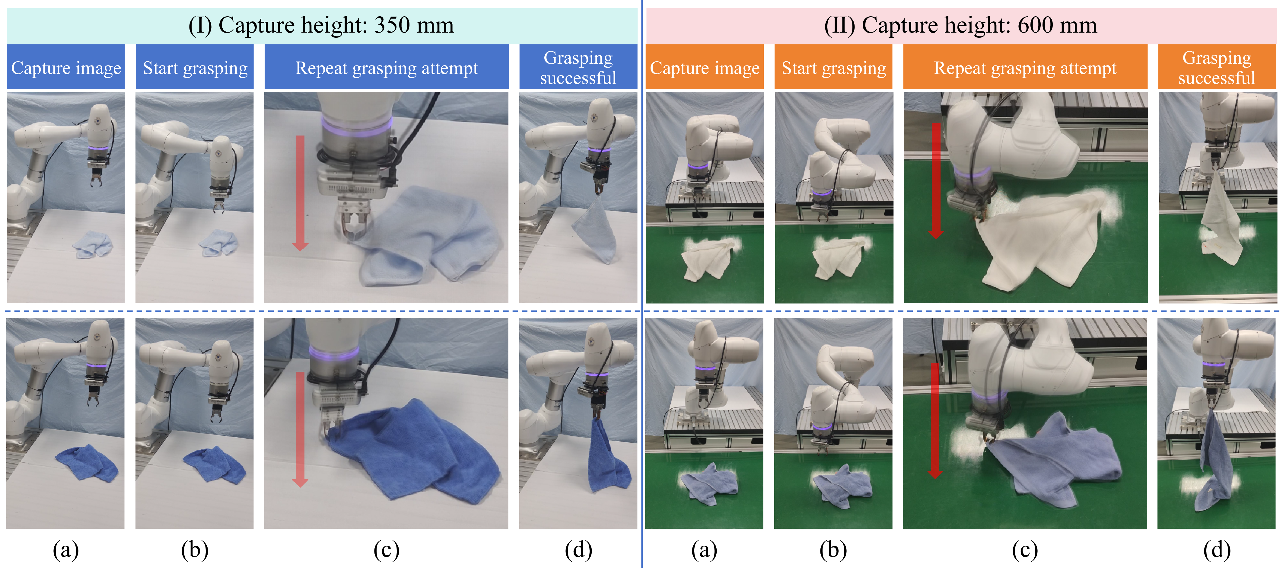
Representative robotic grasping examples under two image capture heights. (I) shows the grasping process at a capture height of 350 mm, and (II) shows the grasping process at a capture height of 600 mm. In each group, (a) shows image capture, (b) shows grasp initiation, (c) shows repeated grasping attempt, and (d) shows successful corner grasping.

Figure 14. Long description
This figure shows robotic grasping examples at two camera capture heights: 350 mm and 600 mm. Each group includes four stages: image capture, grasp initiation, repeated grasping attempt, and successful corner grasping. The figure demonstrates that the proposed corner-to-grasp pipeline can operate across different fabric sizes and capture heights.
To explicitly evaluate the robustness of the proposed pipeline under post-grasp fabric state changes, a post-grasp reconfiguration protocol was adopted in the repeated grasping experiments. In each recognition-and-grasping cycle, the robot first recognized a visible fabric corner and attempted to grasp it according to the proposed corner-to-grasp strategy. After a successful grasp, the fabric was lifted to a certain height and then immediately released, allowing it to fall freely onto the platform and form a new random posture. The next round of fabric corner recognition and grasping was then performed on this updated fabric state. In this way, the system was repeatedly tested under continuously changing fabric configurations rather than under a fixed manually prepared state.
Two different image capture heights were used to evaluate the grasping performance for fabrics of different sizes, as shown in Figure 14. The experiments show that the proposed corner recognition and grasping pipeline can operate effectively across different fabric sizes and colors. Even when the fabric exceeds the camera field of view, visible fabric corners can still be recognized and grasped.
A total of 100 recognition-and-grasping trials with post-grasp reconfiguration were carried out to examine the repeatability and robustness of the corner-to-grasp execution process under varying fabric configurations. Since the fabric samples are lightweight and far below the nominal operating range of the robot-gripper system, the experiments mainly emphasize grasping feasibility, repeatability, and robustness to state changes rather than payload-limit characterization.
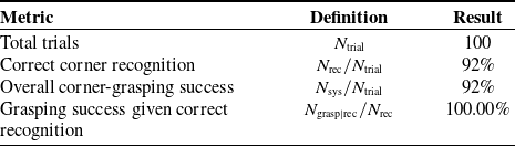
For a more transparent evaluation of the complete robotic pipeline, three trial-level metrics were additionally reported. Let
 $N_{\mathrm{trial}}$
denote the total number of recognition-and-grasping trials,
 $N_{\mathrm{rec}}$
the number of trials in which the fabric corner was correctly recognized,
 $N_{\mathrm{sys}}$
the number of trials in which the system both recognized the intended fabric corner and successfully grasped and lifted it, and
 $N_{\mathrm{grasp|rec}}$
the number of successful grasping trials among the correctly recognized cases. The perception success rate, overall corner-grasping success rate, and grasping success rate conditioned on correct recognition are defined as
 \begin{equation} R_{\mathrm{rec}}=\frac {N_{\mathrm{rec}}}{N_{\mathrm{trial}}}, \quad R_{\mathrm{sys}}=\frac {N_{\mathrm{sys}}}{N_{\mathrm{trial}}}, \quad R_{\mathrm{grasp|rec}}=\frac {N_{\mathrm{grasp|rec}}}{N_{\mathrm{rec}}} \end{equation}
The corresponding results are summarized in Table IV. The results show that the overall system performance is primarily limited by the corner-recognition stage. Once a correct corner point and its bisector direction are obtained, the feedback-guided top-down grasping strategy achieves stable execution, with
 $R_{\mathrm{grasp|rec}}=100.00\%$
in the tested trials. These results also indicate that the system can continue to perform corner recognition and grasping after the fabric state is immediately altered by post-grasp lifting and free release.
Robotic grasping performance under repeated post-grasp reconfiguration trials.

Table IV. Long description
A table with four rows and three columns. The columns are labeled Metric, Definition, and Result. The rows are as follows: Row 1: Metric, Total trials; Definition, N trial; Result, 100. Row 2: Metric, Correct corner recognition; Definition, N rec / N trial; Result, 92 percent. Row 3: Metric, Overall corner-grasping success; Definition, N sys / N trial; Result, 92 percent. Row 4: Metric, Grasping success given correct recognition; Definition, N grasp / N rec; Result, 100.00 percent.
In the tested trials, grasping failure was mainly associated with perception uncertainty in difficult fabric states. When a visible corner was partially occluded, weakened by local shadows, or confused with wrinkle-induced pseudo-corner structures, the selected grasp point could deviate from the intended fabric corner, causing the gripper to contact a flat region or an unstable fold. By contrast, once a correct corner point and its bisector direction were obtained, the feedback-guided top-down grasping strategy showed stable execution and successful corner lifting in repeated trials. These results indicate that the main challenge lies in robust corner perception under complex fabric configurations, whereas the execution strategy is sufficiently stable for the lightweight fabrics considered in this work.
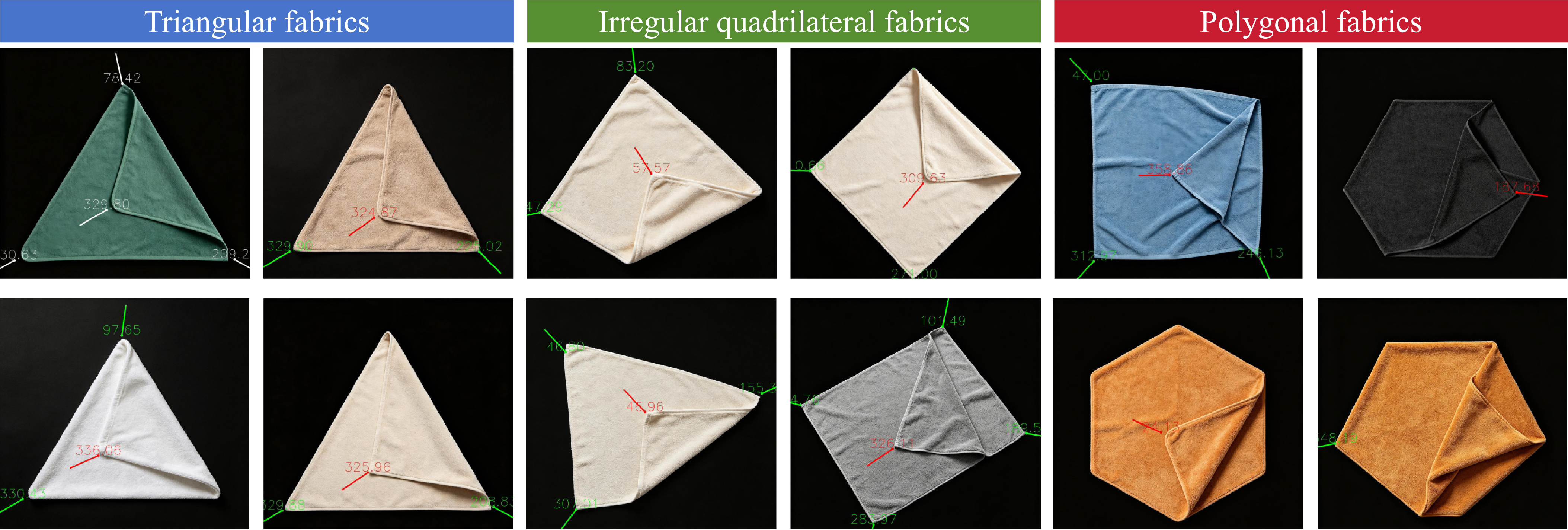
4.5. Supplementary capability-limit evaluation on non-rectangular fabrics
Since the proposed method relies on fixed geometric angle constraints and line-based corner reasoning, its current design is more naturally suited to rectangular or near-rectangular fabric corners. To further examine its capability boundary, supplementary experiments were conducted on non-rectangular solid-color fabrics without changing the main parameter settings used in the primary experiments. The tested samples included triangular fabrics, irregular quadrilateral fabrics, and polygonal fabrics, as shown in Figure 15.
The quantitative recognition results are summarized in Table V, using the same recognition rate, FP ratio, and missed detection rate definitions as in Eq. (14). The corresponding raw recognition counts were 28 TP, 9 FP, and 13 FN for triangular fabrics; 44 TP, 7 FP, and 12 FN for irregular quadrilateral fabrics; and 26 TP, 14 FP, and 34 FN for polygonal fabrics. The results show that the method retains partial recognition capability for triangular and irregular quadrilateral fabrics, while its performance decreases notably for polygonal fabrics whose corner angles deviate more significantly from the predefined geometric assumptions.
Capability-limit recognition results on non-rectangular fabrics.

Table V. Long description
The table presents the quantitative recognition results for different types of fabrics. It has five columns: Shape type, No. of images, Annotated visible corners, Recognition rate (%), FP ratio (%), and Missed detection rate (%). The table includes data for three shape types: Triangular fabrics, Irregular quadrilateral fabrics, and Polygonal fabrics. Each row provides the number of images, annotated visible corners, recognition rate, false positive (FP) ratio, and missed detection rate for each fabric type. For triangular fabrics, there are 20 images, 41 annotated visible corners, a recognition rate of 68.29 percent, an FP ratio of 21.95 percent, and a missed detection rate of 31.71 percent. For irregular quadrilateral fabrics, there are 20 images, 56 annotated visible corners, a recognition rate of 78.57 percent, an FP ratio of 12.50 percent, and a missed detection rate of 21.43 percent. For polygonal fabrics, there are 20 images, 60 annotated visible corners, a recognition rate of 43.33 percent, an FP ratio of 23.33 percent, and a missed detection rate of 56.67 percent.
Supplementary corner recognition results on non-rectangular fabrics without changing the main parameter settings. From left to right: triangular fabrics, irregular quadrilateral fabrics, and polygonal fabrics. The method remains effective for corners whose geometry is close to the rectangular-case angular assumptions, whereas the recognition of polygonal external corners becomes less reliable when the corner angles deviate more significantly.

Figure 15. Long description
This figure shows supplementary recognition results on non-rectangular fabrics without changing the main parameter settings. The tested cases include triangular fabrics, irregular quadrilateral fabrics, and polygonal fabrics. The examples show that the method retains partial recognition capability when corner geometry is close to the rectangular-case assumptions, but recognition becomes less reliable for polygonal fabrics with more significantly deviated corner angles.
Robotic grasping was also evaluated for correctly detected non-rectangular fabric corners. A total of 60 grasping trials were conducted, with 20 trials for each non-rectangular fabric category. All 60 grasping trials were successful, corresponding to a grasping success rate of 100.00% given correct corner recognition. These results indicate that the main limitation in the non-rectangular cases lies primarily in corner recognition rather than in the subsequent grasp execution stage.
5. Discussion and limitations
The experimental results indicate that the proposed framework can effectively support fabric corner recognition and robotic grasping in constrained tabletop environments. By combining LSD-enhanced line perception, LS-CDCT-based structural recovery, and chain-level geometric reasoning, the method provides an interpretable and lightweight alternative to heavily trained perception pipelines for the recognition of visible fabric corners. The robotic grasping results further demonstrate that the detected corner positions and bisector orientations can be directly translated into executable grasping actions through the proposed feedback-guided top-down strategy.
A key design choice of this work is the adoption of an RGB-only perception setting. In the target scenario considered here, this choice reduces sensing complexity, computational burden, and deployment cost, while remaining sufficient for recognizing visible corner-supporting structures from fabric images. At the same time, this should also be regarded as a limitation of the current system. Since direct depth cues are not used, the method relies on image-based geometric reasoning and a grasping strategy that tolerates height uncertainty during execution. Although this design is suitable for thin and deformable fabrics in constrained tabletop conditions, richer depth information may still be beneficial in more general manipulation scenarios involving severe self-occlusion, stacking, or large out-of-plane deformation.
The current framework is mainly applicable to constrained tabletop or production-line scenarios involving small- to medium-sized solid-color fabrics with relatively clear visible corner structures. As shown by the experimental observations, the method is more reliable for external fabric corners than for internal ones, because external corners usually provide clearer boundary-supporting line structures, whereas internal corners are more easily influenced by folds, shadows, and partial occlusion. Compared with the current experimental setup, practical applications may involve moving conveyors, more complex backgrounds, stronger illumination variation, patterned or dark fabrics, severe occlusion, and stacked fabrics, which may degrade performance by affecting background removal, line segment detection, chain completion, and corner reasoning.
In addition, the method may be less effective for several challenging fabric conditions beyond the patterned and large-fabric cases mentioned above. For dark fabrics, weak image contrast and underexposed boundary regions may reduce the visibility of corner-supporting edges, making the extracted line structures incomplete or unstable. For highly reflective fabrics, specular highlights and local saturation can introduce spurious bright boundaries and interrupt true contour continuity, which may lead to false intersections or missing supporting segments. For heavily wrinkled fabrics, dense local creases generate many short line fragments and pseudo-corner structures, increasing the difficulty of distinguishing true fabric corners from wrinkle-induced geometric responses. For stacked or partially overlapping fabrics, visible corners can still be detected in some cases, but occlusion, layer interaction, and boundary mixing may introduce ambiguous supporting structures and make corner attribution less stable. In all of these cases, the main difficulty is that the RGB-only image no longer provides sufficiently stable boundary-supported geometric evidence for reliable corner reasoning.
It should also be noted that the current framework still relies on fixed geometric angle constraints. In practical deployment, for several known fabric shape categories, such as triangular, irregular quadrilateral, and polygonal fabrics, shape-specific parameter presets can be prepared in advance and directly invoked according to task requirements. This may improve recognition performance for particular shape classes, but it also indicates that the current implementation still depends on manually specified geometric priors rather than fully shape-independent corner reasoning.
The comparative study includes several traditional geometry-based baselines and detector-replacement variants but does not cover modern learning-based cloth keypoint detectors or RGB-D-based manipulation systems. The reported comparison therefore mainly reflects the performance of the proposed lightweight LS-CDCT-based geometric reasoning framework within traditional RGB-based vision settings. Broader comparisons with learning-based and multimodal perception methods will be considered in future work.
Future work will focus on improving the robustness of line perception and corner reasoning under more challenging visual conditions, extending the method to a broader range of fabric types, and incorporating more comprehensive comparative experiments. For practical deployment, controlled illumination, stable camera calibration, background simplification, and task-specific parameter presets may be adopted to reduce the gap between the current experimental setup and real application environments. In addition, we plan to explore more advanced robotic manipulation settings, including dual-arm coordination and more complex fabric state transitions, so as to further extend the applicability of the proposed framework.
6. Conclusion
This paper presents an LSD-enhanced line perception and structural recovery framework for fabric corner recognition and robotic grasping in constrained tabletop environments. Starting from raw line detections, the proposed LS-CDCT progressively repairs, filters, merges, completes, and organizes fragmented line structures into refined line segment chains, which are then used for geometric fabric corner reasoning. Based on the detected corner positions and bisector orientations, a corner-to-grasp robotic execution pipeline is further constructed to achieve automatic fabric corner grasping.
Experimental evaluation on 160 fabric images containing 489 visible fabric corners demonstrates the effectiveness of the proposed framework. The method achieves an overall corner recognition rate of 92.84%, with a recognition rate of 94.63% for visible external fabric corners. In robotic experiments, 100 recognition-and-grasping cycles were conducted. The overall corner-grasping success rate reached 92.00%, while the grasping success rate conditioned on correct corner recognition reached 100.00%. In comparison with the raw LSD-based baseline, the proposed framework shows clear advantages in recognition rate and robustness for randomly configured small- to medium-sized solid-color fabrics.
Overall, the proposed method provides a lightweight, interpretable, and practically deployable solution for visible fabric corner recognition and robotic grasping under constrained perception settings. Beyond the specific application studied in this work, the idea of combining line perception enhancement, structural recovery, and geometry-based reasoning may also provide useful insight for other lightweight robotic vision tasks involving incomplete or fragmented visual structures.
Acknowledgments
Supported by the Open Research Project of Innovation Center of Yangtze River Delta, Zhejiang University.
Author contributions
Ziyue Hao was responsible for the overall design of the proposed method, including the development and implementation of the detection algorithm, the construction of the line segment processing and fabric corner recognition framework, the experimental analysis, and the writing and revision of the manuscript; Ze’an Liu contributed to the experimental design and optimization and was responsible for the design, implementation, and refinement of the robotic system control architecture; Shuo Yang conducted and supervised the overall experimental procedures; Feng Pan contributed to the experimental preparation and related experimental design work; Xuanyin Wang performed the background investigation and contributed to the realization of the application scenarios.
Financial support
This research received no specific grant from any funding agency, commercial, or not-for-profit sectors.
Competing interests
The authors declare no conflicts of interest exist.
Ethical approval
Not applicable.
Author biographies
Ziyue Hao received his B.E. degree in mechanical engineering from Beijing Jiaotong University, Beijing, China, in 2023. He is currently pursuing his Ph.D. degree in the School of Mechanical Engineering, Zhejiang University, Hangzhou, China. His current research interests include collaborative robots and machine vision.
Ze’an Liu received his Ph.D. degree in mechanical engineering from Zhejiang University in 2025. He is now working at China Mobile (Hangzhou) Information Technology Co., Ltd. as an algorithm engineer. His current research interests include machine vision and robotics.
Shuo Yang received the B.E. degree in automation from Zhejiang University, Hangzhou, China, in 2023, where he is currently pursuing the Ph.D. degree with the School of Mechanical Engineering. His current research interests include robotics and reinforcement learning.
Feng Pan received his Ph.D. degree in mechanical engineering from Zhejiang University in 2005. He is now working at Zhejiang Sunny Optical Intelligence Technology Co., Ltd. as the principal engineer. His current research interests focus on image processing and intelligent machines.
Xuanyin Wang received his Ph.D. degree in mechanical engineering from Harbin Institute of Technology, Harbin, China, in 1995. He is currently a professor in the State Key Laboratory of Fluid Power and Mechatronic Systems at Zhejiang University. His main research interests are intelligent machine, image vision information technology, and multi-degree of freedom motion servo control.
Appendix A. Main parameter settings and compact robustness verification
For reproducibility, the main parameters reported below correspond to the values explicitly used in the manuscript. To keep the main text concise, only a compact one-at-a-time robustness verification is provided here for representative thresholds, while all other parameters are kept fixed.
Main parameter settings used in the proposed framework

Table A1. Long description
This table summarizes the main parameters used in the proposed framework. It includes image-scale thresholds for resolution-aware preprocessing, image rescaling factor, chain filtering threshold, repair and filtering length thresholds, Tail-Seeking search range and distance threshold, internal and external corner angle ranges, pruning and replacement distance threshold, repair and merging thresholds, Tail-Seeking angular threshold, projection-completion threshold, and intersection-merging threshold. For each parameter, the table lists its value, role, and selection principle.
Compact one-at-a-time robustness verification for representative parameters

Table A2. Long description
This table reports a compact robustness verification by perturbing representative parameters one at a time while keeping other parameters fixed. The evaluated parameters include repair length threshold, Tail-Seeking distance, internal corner angle range, and external corner angle range. For each perturbation, the table reports recognition rate, FP ratio, missed rate, and an observation about the effect of the parameter change. The results show that recognition performance remains reasonably stable under moderate parameter perturbations, although looser or stricter angle ranges affect false positives and missed detections.
Appendix B. Detailed pseudocode of the LS-CDCT framework
Repair and filter short line segments

Algorithm 1 Long description
An equation describing an algorithm for refining line segments. The algorithm initializes thresholds and iterates over all line segments. If a segment’s length is below a threshold, it finds the nearest segment and checks if they are close enough and have a small enough angle to be connected. If so, it marks them as merged. After processing all segments, it removes any segments that are still too short. The refined line segments are then returned.
Merge parallel or overlapping line segments

Algorithm 2 Long description
An algorithm for merging line segments. The process starts by initializing the final merged line segments. For each unmerged segment, a merging set is initialized. The algorithm then iterates, computing the angle and vertical distance between segments. If these values are below specified thresholds and projections overlap, the segment is added to the merging set. This repeats until no new segments are added. All segments in the merging set are then merged using extreme endpoints and added to the final merged line segments.
Tail-Seeking and line segment chain construction

Algorithm 3 Long description
Panel A: The flowchart begins with segment division, where each line segment is divided into sub-segments. Panel B: The tail-seeking connection step involves searching for candidate endpoints within a specified angle and distance, connecting sub-segments if criteria are met. Panel C: The chain organization step initializes a chain set, assigns chain IDs, computes chain attributes, and adds chains to the set.
Edge/internal chain filtering

Algorithm 4 Long description
Panel A: A flowchart outlining the steps for filtering line segment chains. Panel B: A diagram showing the process of examining chain endpoints in four neighboring directions. Panel C: A visual representation of the filtering process with chains classified as edge or internal.
Corner completion: Projection and replacement points

Algorithm 5 Long description
The algorithm starts with a line segment chain set and a projection-completion threshold. It iterates over all endpoints in the set. For each endpoint, it finds the nearest line segment chain for pairing and computes projection coefficients and constrained values using given equations. It then calculates the projection point and distance. If the distance is below the threshold, the endpoint is replaced with the projection point, which is stored as a replacement point. This process continues until all endpoints are processed, and the updated line segment chain set is returned.
Corner completion: Type I/II corner handling and pruning

Algorithm 6 Long description
An image displaying a formal pseudocode block for a computer vision or geometry-based algorithm designed to refine and prune a set of geometric chains.
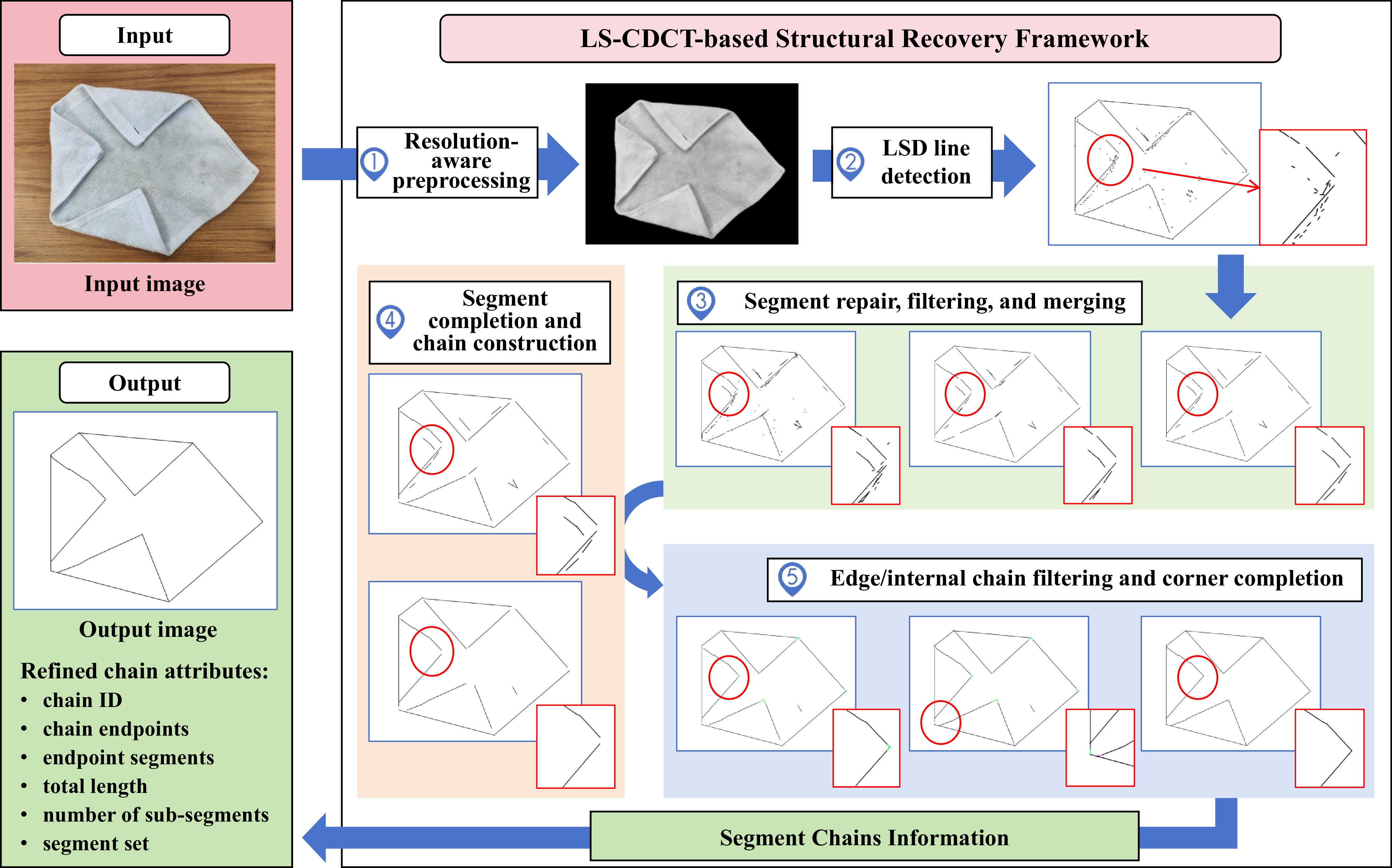
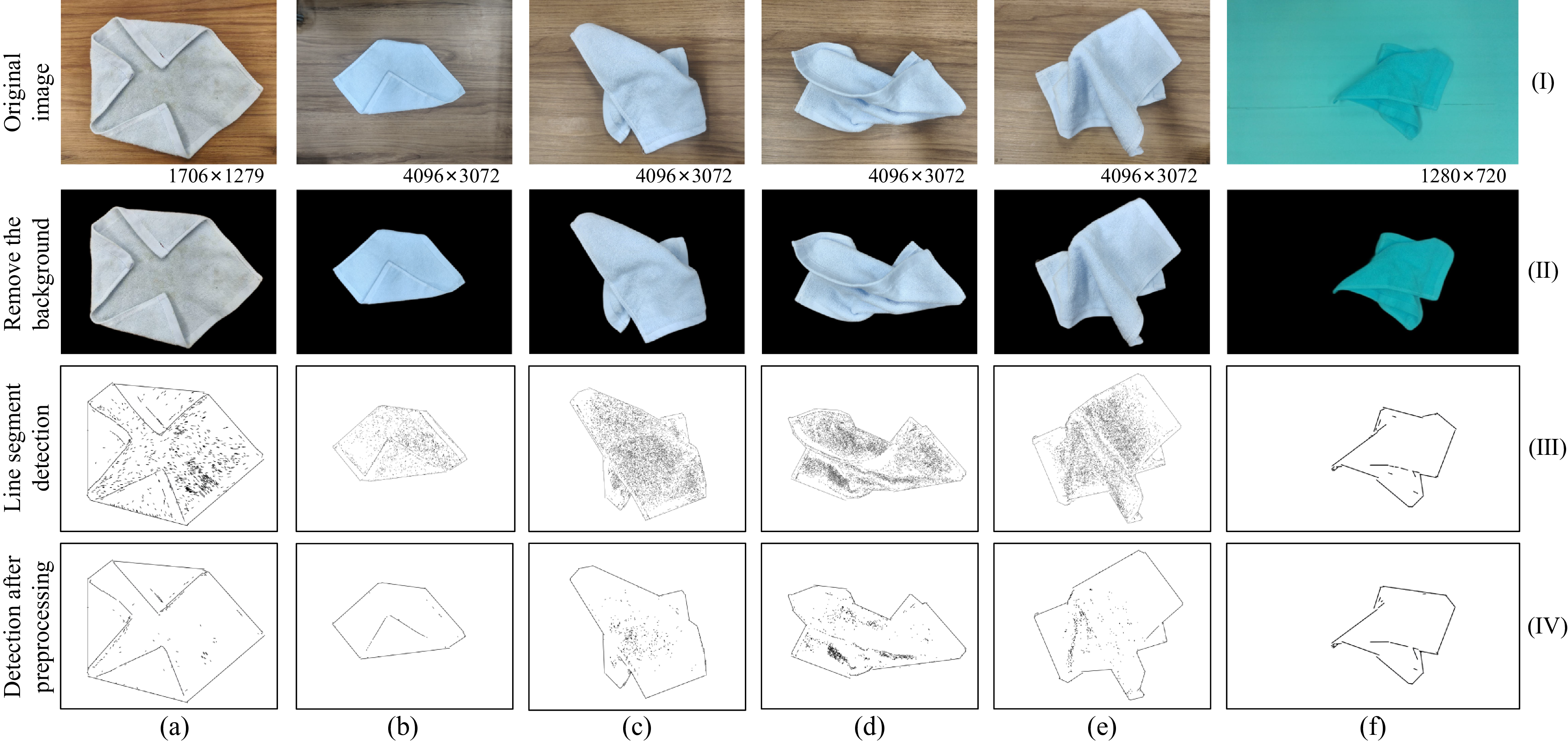
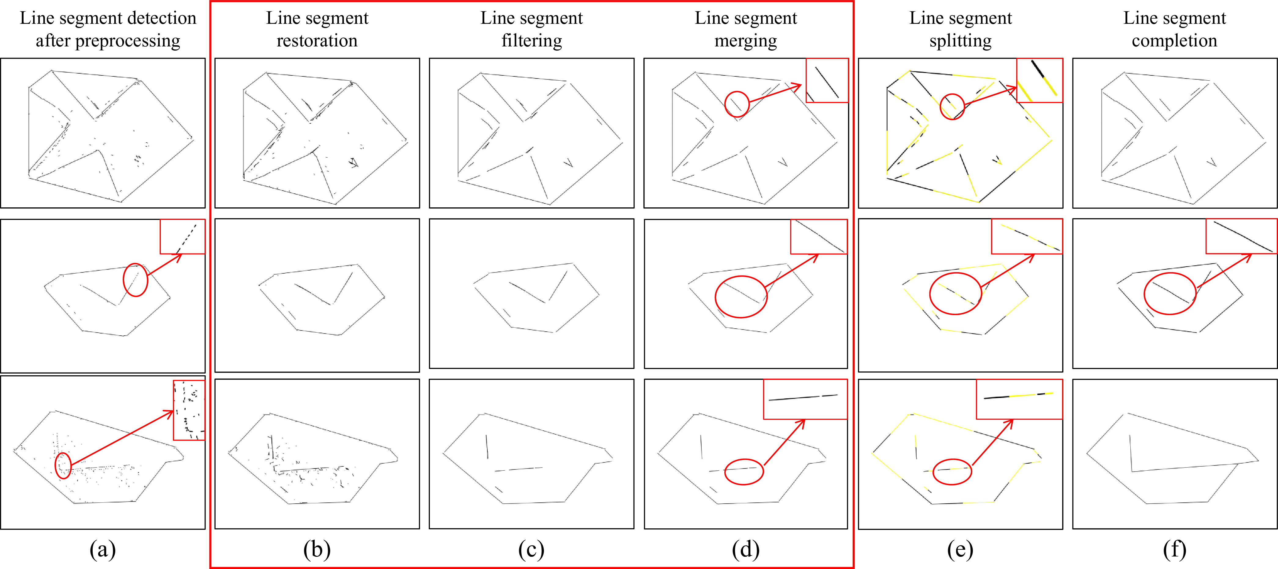
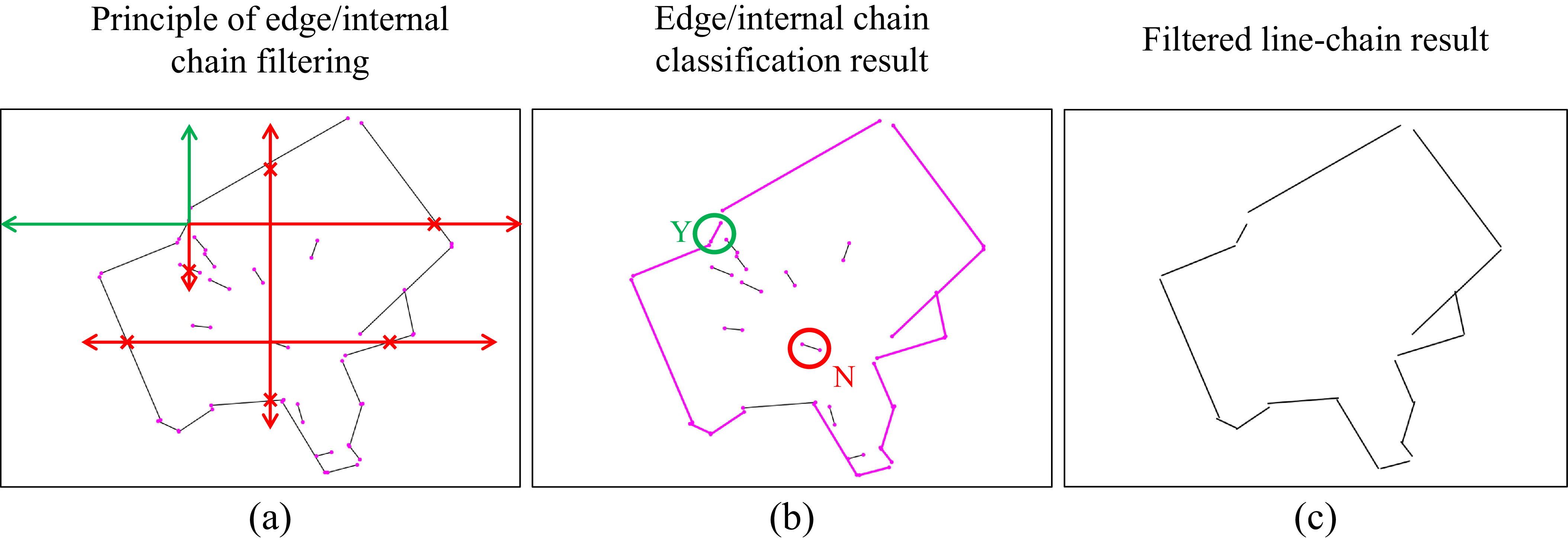
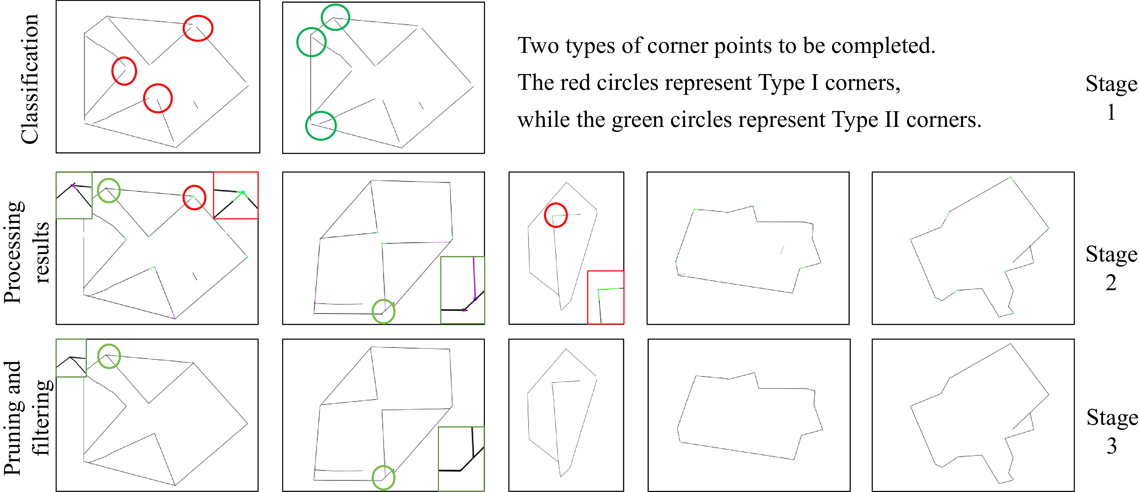
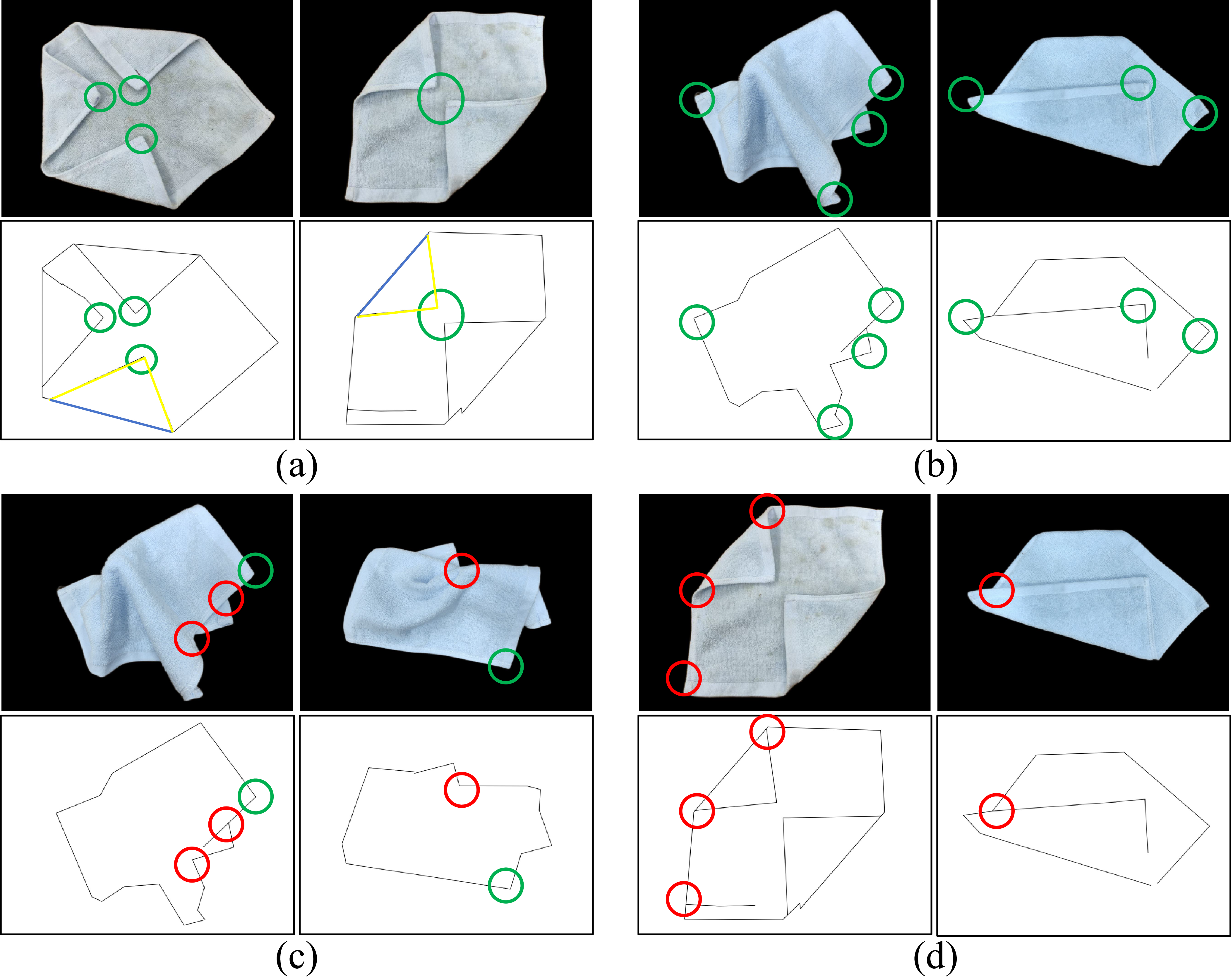
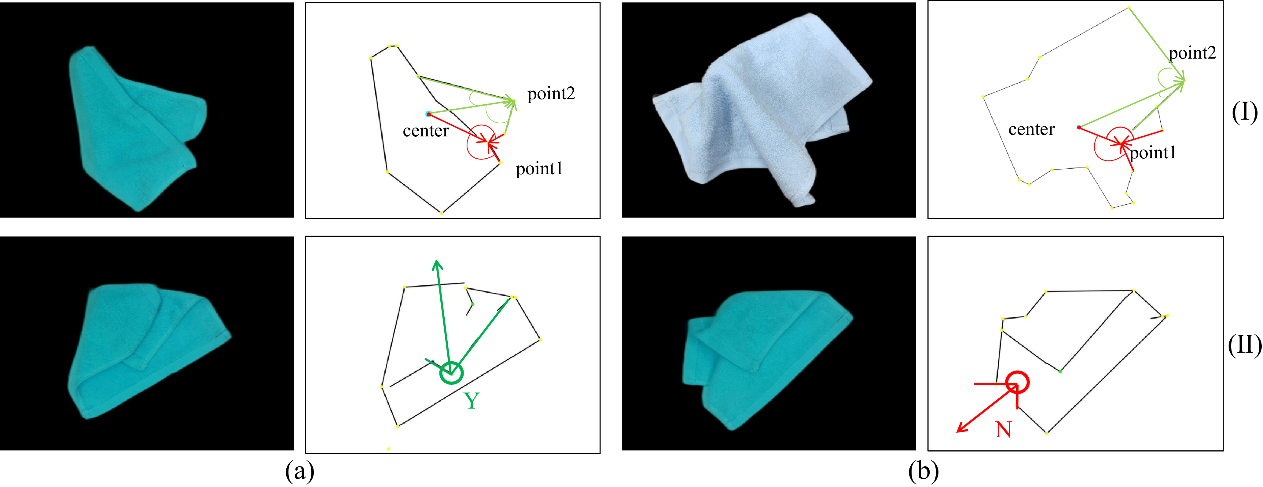
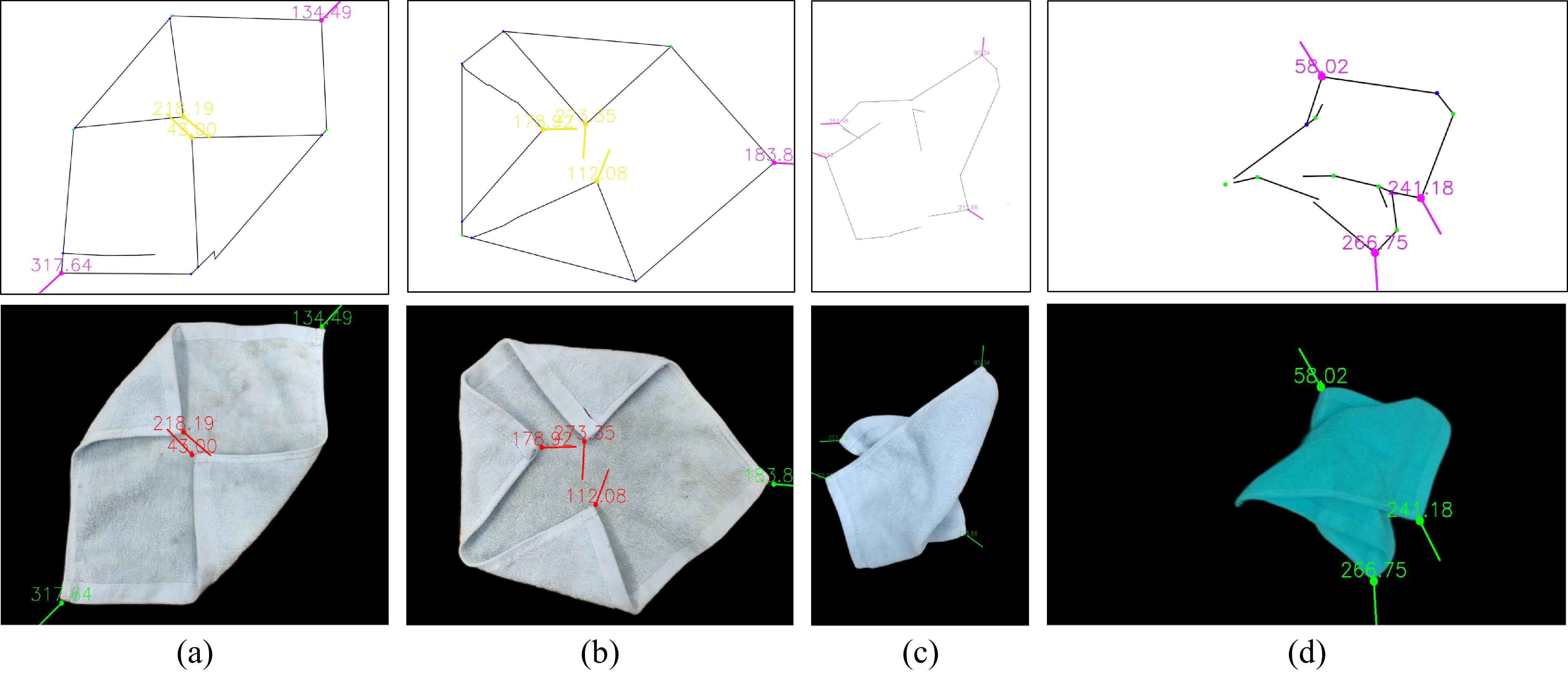
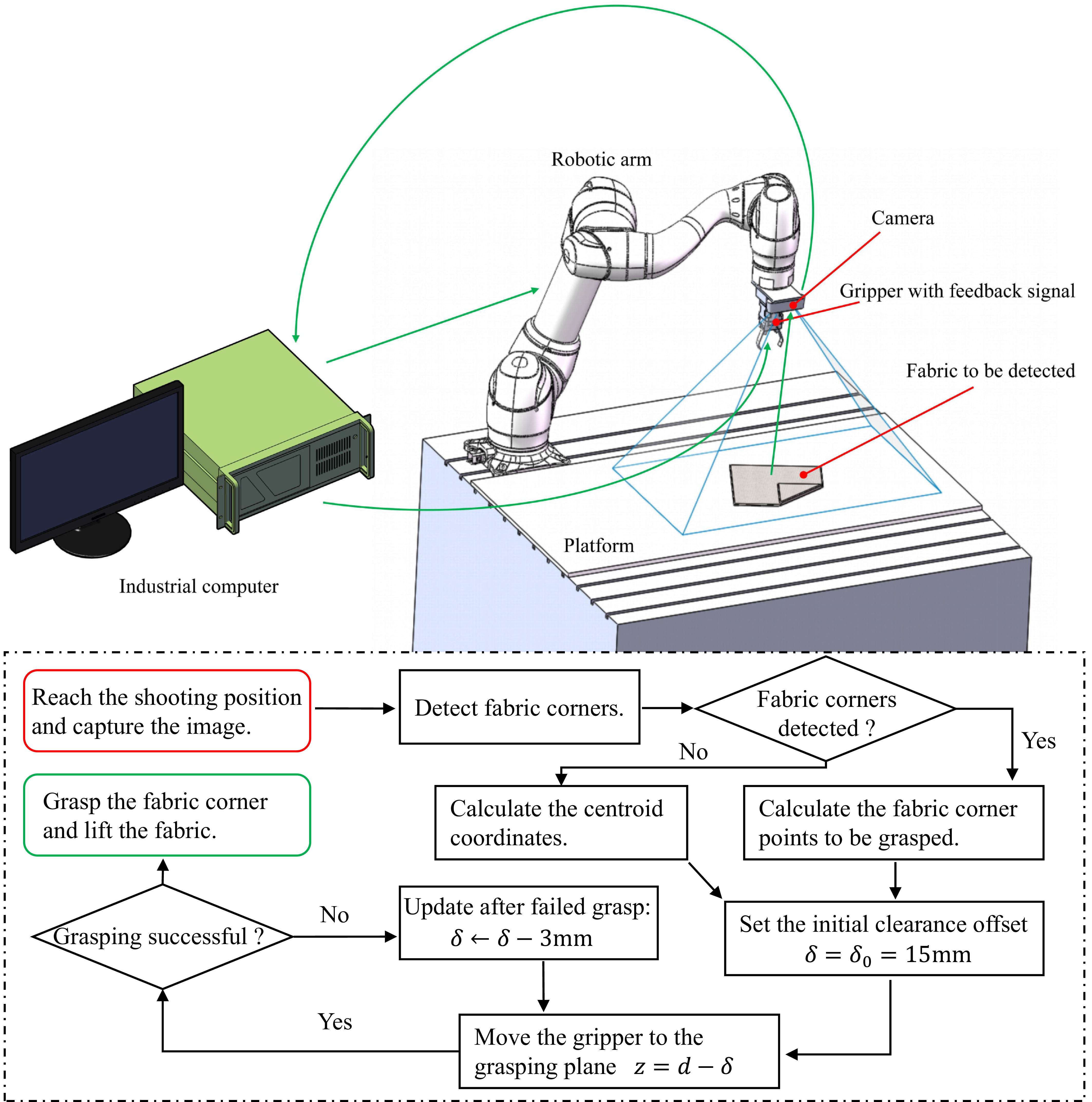
 d
 δ
 z=d−δ
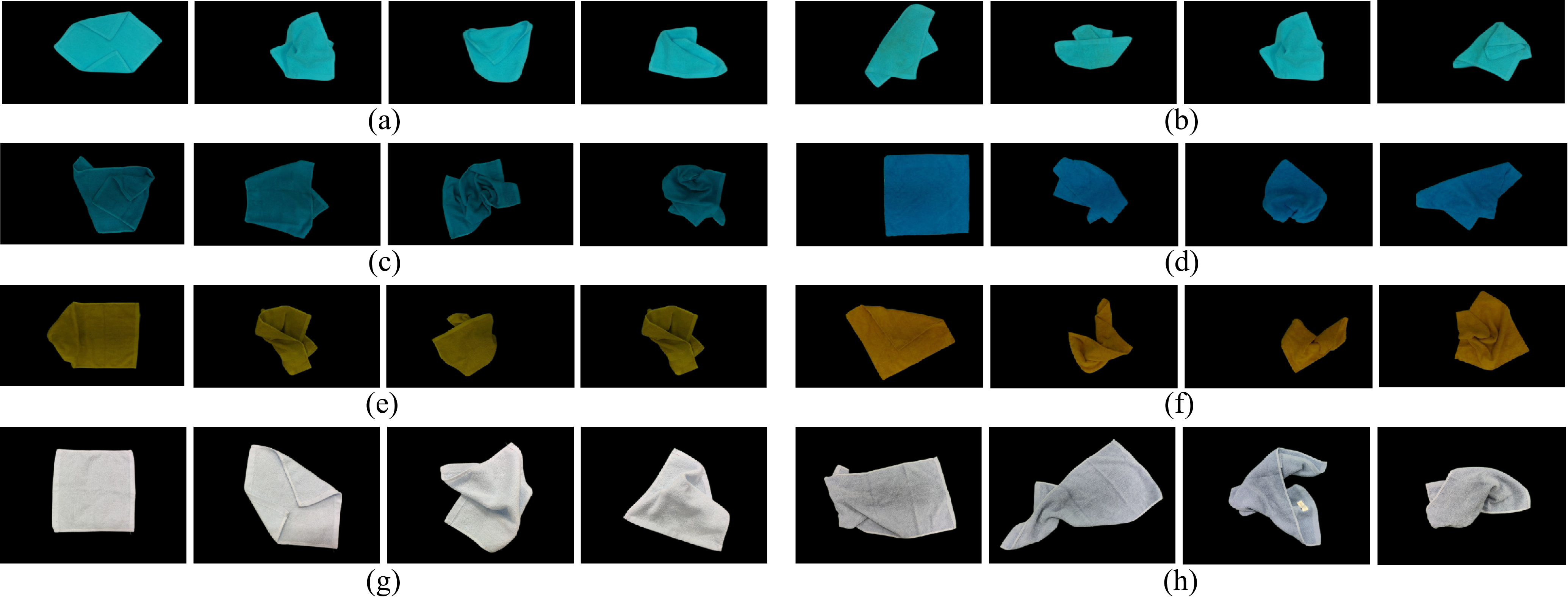
 ×
 ×
 ×