I. INTRODUCTION
Aluminum foam is a kind of porous metal, which has lots of cellular pores inside. According to Chen and LiReference Chen and Li1 and Banhart,Reference Banhart2 besides low density, high specific strength, and high specific stiffness, the aluminum foam also has performances of sound absorption and crash energy absorption. The gas injection foaming process is an important method to produce the aluminum foam. Its product usually has big pores and high porosity, about 5–25 mm and 90 ∼ 98% according to Banhart.Reference Banhart2 In this process, the gas containing oxygen is injected by a nozzle into the aluminum melt, which contains ceramic particles. According to Babcsán et al.,Reference Babcsán, Leitlmeier, Degischer and Banhart3 via adsorbing the particles and forming the oxide layers, the bubbles will not burst after floating on the melt surface and then form the foam.
KennyReference Kenny4 had proved that the performance of the aluminum foam was affected by the pore size. The pore size mainly depends on the size of the bubbles created by the nozzle. The nozzle has two types, dynamic type and static type. The dynamic nozzle creates bubbles by relative motion between the orifice and the melt.Reference Jin, Kenny and Sang5 However, the static nozzle keeps still, and the bubble size depends on the nozzle's structure.Reference Leitlmeier, Degischer and Flankl6 In this study, the static nozzle was used.
For a static nozzle, the parameters influencing the bubble size are the nozzle's wettability, inner and outer diameters of the orifice, gas chamber volume, orifice number, gas flux, and so on. According to the reviews by Kulkarni and Joshi,Reference Kulkarni and Joshi7 and by Yang et al.,Reference Yang, Du and Fan8 many researches have studied these factors. Recent researches mostly focus on the dynamic process of bubble formation by the numerical method. As a matter of fact, early researches, which got empirical or semiempirical formula based on a large amount of experimental data, also have an important reference value for today's study. Some of them are main references of this study.
Gnyloskurenko et al.Reference Gnyloskurenko, Byakova, Nakamura and Raychenko9 found that when the nozzle's wettability is bad, the three-phase-boundary of the bubble would spread to the outer diameter of the nozzle. And it results in big bubbles. They found that nozzle with better wettability could create smaller bubbles. Because their experiments were carried out in the liquid aluminum, the conclusion is suitable for the gas injection foaming process in aluminum melt.
Davidson and AmickReference Davidson and Amick10 presented a semiempirical formula about the influence of the gas flux and the nozzle diameter on the bubble size. The formula agreed well with the air bubbling experiments, which were carried out in the aqueous system (water and mineral oil). The nozzle was a hole in a brass sheet or was a tube made of brass or copper. The wettability of brass and copper in the aqueous system was good.
Park et al.Reference Park, Tyler and Nevers11 studied the effect of the gas chamber volume on air and nitrogen bubble size in the aqueous system (water, iso-octane, and glycerine). The nozzle was a hole in a thin sheet made of brass or teflon. The materials' wettability in the aqueous system was good. In their study, when the gas chamber volume was small, it did not affect the bubble size. If it was moderate, the bubble size would increase with its increase. If it was too large, it did not affect the bubble size any more.
Sano and MoriReference Sano and Mori12 investigated the effect of the wettability, the gas chamber volume, the nozzle diameter, and the gas flux on the bubble size. They used the silica nozzle to produce air and nitrogen bubbles in mercury, liquid silver, water, and alcohol. The nozzle's wettability was good in some conditions and bad in other conditions. They found that the influence of the gas chamber volume had different stages, similar to Park et al.Reference Park, Tyler and Nevers11 Based on previous researches, including Davidson and Amick's study,Reference Davidson and Amick10 Sano and MoriReference Sano and Mori12 presented a semiempirical formula to calculate the bubble size. For wetted and nonwetted nozzles, the formula was different. They also discussed the effect of temperature when bubbling in liquid silver. However, the effect of temperature needs further discussion (see Sec. IV. A).
Irons and GuthrieReference Irons and Guthrie13 proved that the formula presented by Sano and MoriReference Sano and Mori12 was reasonable by the argon bubbling experiments in liquid pig iron with the graphite nozzle, which was not wetted. They modified the parameters of the formula to agree with their experimental data. More important, they found that although the gas chamber volume had been very large, the bubble size continued to increase with its increase. The conclusion was different from the one described by Sano and MoriReference Sano and Mori12 and Park et al.Reference Park, Tyler and Nevers11
This literature studied the influencing parameters of the bubble size. However, because of the different experimental conditions, some conclusions and the formula presented by Sano and MoriReference Sano and Mori12 may be not applicable for bubbling in aluminum melt. In this study, first, the influences of the factors on the bubble size in the aluminum alloy melt during the foaming process are studied. Then, the formula is modified based on the experimental data.
II. EXPERIMENTAL
A. Foaming process
A356 aluminum alloy was used in the experiments. 10 vol% Al2O3 particles, size of 9 μm, were added into the alloy melt by a mechanical stirrer. To clear impurity and gas on the surface, the particles were heated to 400 °C and held for several hours before adding. During adding, the particles were divided into several parts. The detailed parameters about stirring particles were introduced in the authors' previous study.Reference Liu14
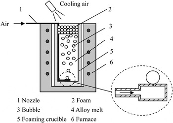
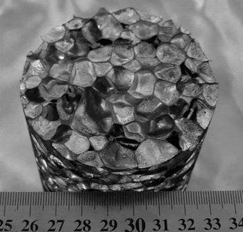
Then, the mixture was carried into a foaming crucible and the air was injected to produce the foam, shown in Fig. 1. According to the authors' previous studies,Reference Liu, Li, Chen, Liu and Fan15,Reference Liu and Li16 the foam had enough stability under the experimental conditions. The nozzle was a stainless steel sheet with one or more orifices, which is wetted by the aluminum alloy melt, shown in Fig. 1. The thickness of the sheet is 2 mm. When the nozzle has more than one orifice, the distance between the two nearest orifices is large enough to avoid emerging of bubbles. The aluminum foam produced by this processing is shown in Fig. 2.
Schematic of the gas injection foaming process.

Sample of the aluminum foam.

B. Bubble size
In this study, the “bubble size” means the size of the bubble in its last state, when the bubble had reached the surface of the melt. Because the bubble has only a little gas inside, before it reached the surface, the gas temperature had been the same with the one of the melt, about 933–1003 K in this study. The depth of the melt is less than 200 mm, so the expansion of the bubble due to reducing pressure during rising was ignored. The foaming crucible opened in the atmosphere, and there was cooling air above the foam. When the bubbles reached the surface, they solidified within several seconds. And the bubbles' coalescence is rare. The temperature of the A356 solid–liquid two-phase region is about 850–888 K. After solidification, the diameter of the bubble will decrease by less than 5.7%, from 1003 to 850 K. This value is less than the calculation error by the semiempirical formula (see Sec. IV). So for simplicity, the foam pore size is used to replace the “bubble size” which was not able to be measured directly.
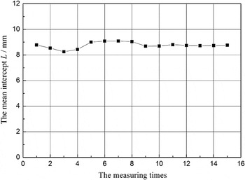
The foam pore size was measured by the mean intercept method.Reference Liu17 The mean intercept is denoted as L, and the pore size D = L/0.616. Figure 3 shows the relationship between the mean intercept and the measuring times. Measuring more than 10 times can get the stable result.
Relationship between the mean intercept L and the measuring times.

C. Gas circuit
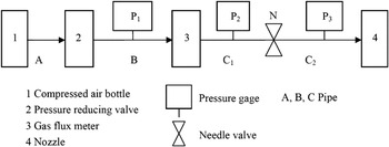
The gas circuit is shown in Fig. 4. The concept of the “gas chamber volume” is the volume of the space between the orifice and the nearest place where there is a large pressure loss.Reference Sano and Mori12 In our experiments, when the needle valve is totally opened, there is no pressure loss after pressure reducing valve. So, the gas chamber volume comprises the space of three pipes, B, C1, and C2, and the space of the nozzle. When the needle valve is not closed totally, named “half-closed,” it causes a large pressure loss. Then, the gas chamber volume comprises the space of pipe C2 and the space of the nozzle. So, the gas chamber volume can be changed by changing the open state of the needle valve and by changing the space of the nozzle or the pipes.
Schematic of the gas circuit in experiments.

The gas flux in this study is the equivalent value under 101,325 Pa and 293.15 K. It is the reading of flow meter 3, corrected by the pressure gage P 1 and the environment temperature.
D. Experimental parameters
In the experiments, the effects of the orifice diameter, the gas chamber volume, the orifice number, and the gas flux on the bubble size were studied.
First, the effect of the orifice diameter was studied. Some single-orifice nozzles were used. They had the same structure and different orifice diameters: 0.4, 0.51, 0.82, 1.0, 2.4, and 3.0 mm. The gas chamber volume is 11 cm3. The gas flux was 10–100 L/h. The foaming temperature is 933–953 K.
Second, the effect of the gas chamber volume was studied. A nozzle with multiorifice was used. The orifices were 0.3 mm in diameter. The gas chamber volume had two values, 800 and 100 cm3, by changing the state of the needle valve. The foaming temperature is 983–1003 K.
Then, the effect of the orifice number was studied. Two nozzles were used. The orifice was 0.6 mm in diameter, and the gas chamber volume was 45 cm3. One nozzle had a single orifice, and another had four. The foaming temperature is 933–943 K.
At last, the effect of the gas flux was studied. Two single-orifice nozzles were used, with similar structure. The orifice was 0.6 mm in diameter. The gas chamber volume is 45 and 47 cm3, respectively. One nozzle always blew under low flux. And another first blew under high flux, and then under low flux. The foaming temperature is 933–953 K.
III. RESULTS
A. Effect of the orifice diameter
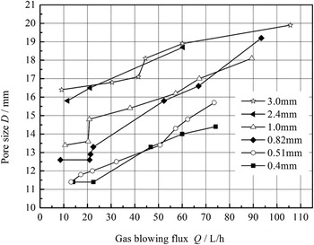
The pore sizes of the foams, produced by some single-orifice nozzles with different orifices in diameter at 933–953 K, are shown in Fig. 5. These nozzles have similar structures and the same chamber volume, 11 cm3. As shown, the pore size increases with the increasing of the orifice diameter and also with the increasing of the gas flux. All the foams were produced in “stable bubbling stage” (see Sec. III. D).
Relationship between the pore size and the gas flux under different orifice diameters (the foam was produced by single-orifice nozzle with the same chamber volume 11 cm3, in “stable bubbling stage,” at 933–953 K.).

B. Effect of the gas chamber volume
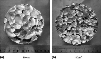
Two foam samples are shown in Fig. 6, produced by the same nozzle with the same gas flux. The nozzle had multiple orifices, 0.3 mm in diameter. The two foams were produced with different gas chamber volumes, by changing the open state of the needle valve (see Sec. II. C). The pore size is 19.1 and 12.3 mm when the gas chamber volume is 800 and 100 cm3, respectively. The pore size decreases significantly with the decreasing of the gas chamber volume. The two foams were produced in “stable bubbling stage” (see Sec. III. D), at 983–1003 K.
Foam samples produced by a multiorifice nozzle whose orifice is 0.3 mm in diameter and gas chamber volume is (a) 800 cm3 and (b) 100 cm3, in “stable bubbling stage,” at 983–1003 K.

C. Effect of the orifice number
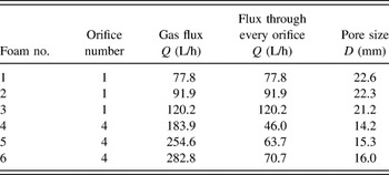
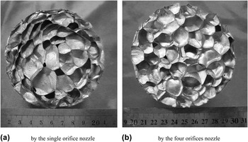
Two nozzles were used to form the foams at 933–943 K. The two nozzles have the same structure, the same orifice diameter (0.6 mm), the same chamber volume (45 cm3), and different orifice numbers (1 and 4). The foaming parameters and the pore sizes are shown in Table I. The foam samples are shown in Fig. 7. As shown, the pore size of the foam formed by four orifice nozzles is smaller than the one formed by the single orifice nozzle. The pores close to the foam's border in Fig. 7(a) were not used to measure the pore size because of compression. All the foams were formed in “metastable large bubble stage” (see Sec. III. D).
Foaming parameters and the pore sizes of the foams, formed by two nozzles with the same orifice diameter 0.6 mm, and the same gas chamber volume 45 cm3, but different orifice numbers, 1 and 4, in “metastable large bubble stage,” at 933–943 K.

Foam samples formed (a) by the single orifice nozzle and (b) by the four orifice nozzles, with the same orifice diameter 0.6 mm and the same gas chamber volume 45 cm3, in “metastable large bubble stage,” at 933–943 K.

D. Effect of the gas flux
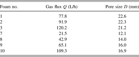
Two single-orifice nozzles were used, with the same orifice diameter, 0.6 mm, and the similar chamber volumes, 45 and 47 cm3. The experimental conditions and the foam pore size are shown in Table II. One nozzle produced foam no. 1 ∼ 3 at 933–943 K, the same as the ones in Table I. The gas flux was always low during the whole processing. Another nozzle produced foam no. 7 ∼ 10 at 933–953 K. The gas flux was once very high before producing foam no. 7 ∼ 10.
Experimental conditions and pore size of the foams, produced by two single-orifice nozzles, with the same orifice diameter, 0.6 mm, and similar gas chamber volume, 45 and 47 cm3, respectively in “metastable large bubble stage,” at 933–943 K, and in “stable bubbling stage,” at 933–953 K.
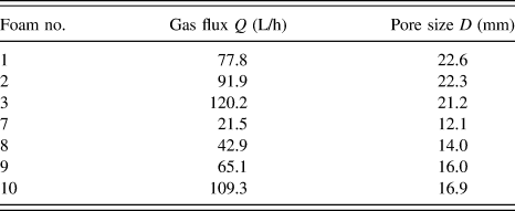
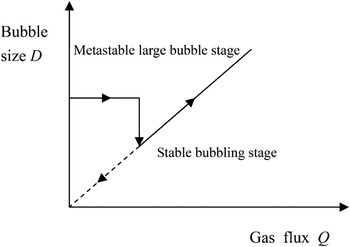
It' is found that the gas flux had a dual-stage effect on the bubble size. If the gas flux is always small during the whole foaming process, the bubble would be always large, and its size will not change with the flux almost, like foam no. 1 ∼ 3 in Table I or Table II. When the gas flux increases to some certain value, the bubble size would decrease suddenly. And then it will change with the flux apparently, like foam no. 7 ∼ 10 in Table II. Even the flux decreases to the former range, where the large bubbles were once produced, the large bubbles cannot be generated any more. The stage when large bubbles come out under low flux is called “metastable large bubble stage,” and the stage when bubble size changes with flux apparently is called “stable bubbling stage”. The relationship between the two stages is shown in Fig. 8.
The dual-stage effect of gas flux Q on the bubble size D.

As a matter of fact, it was found that all the stainless steel nozzles used in this study had this phenomenon, which was more apparent for the smaller orifice. It is may be due to the change in the wettability of the orifice. When the nozzle was put into the aluminum melt, some aluminum oxide would cover the orifice because of the adsorbed air on the surface of the orifice. The oxide would worsen the wettability of the orifice, and it could not be removed by low gas flux. So, large bubbles were generated. After the oxide had been removed by large gas flux, the aluminum melt could cover the orifice because of the good wettability of the stainless steel. From then on, small bubbles could be generated. The phenomenon has not been reported in other literature, in which there were not so special experimental conditions, such as wetted nozzle, liquid metal, and oxidizing gas.
IV. CALCULATION OF THE PORE SIZE
A. Correction of the semiempirical formula
Sano and MoriReference Sano and Mori12 presented Eqs. (1) and (2) to calculate the bubble size (when the nozzle has only one orifice and is wetted):
 $$D\prime = {\left[ {{{3{D_{\rm{o}}}\sigma } \over {g{\rho _{{\rm{lq}}}}}}\mathop {{N_{\rm{c}}}}\nolimits^m + {{\left( {{{9\mathop {{D_{\rm{o}}}}\nolimits^2 {\sigma ^2}} \over {{g^2}\mathop {{\rho _{{\rm{lq}}}}}\nolimits^2 }}\mathop {{N_{\rm{c}}}}\nolimits^{2m} + K{{{Q^2}{D_{\rm{o}}}} \over g}} \right)}^{1/2}}} \right]^{1/3}}\quad ,$$
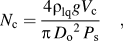 $${N_{\rm{c}}} = {{4{\rho _{{\rm{lq}}}}g{V_{\rm{c}}}} \over {\pi \mathop {{D_{\rm{o}}}}\nolimits^2 {P_{\rm{s}}}}}\quad ,$$
where D′ denotes the bubble size, D o inner diameter of the orifice, σ surface tension of the liquid, g the acceleration of gravity, ρlq density of the liquid, N c the gas chamber parameter calculated by Eq. (2), Q the gas flux, V c the gas chamber volume, P s the static pressure (101,325 Pa in this study), m the correction coefficient for the effect of the gas chamber volume, and K the correction coefficient for the effect of the flux.
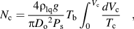
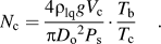
If the gas is heated during the foaming process, Sano and MoriReference Sano and Mori12 proposed that N c should be modified as Eq. (3), where T b and T c denote the temperature in the bubble and in the gas chamber, respectively. Equation (4) is the simplification of Eq. (3) when T c is uniform in the whole gas chamber.
 $${N_{\rm{c}}} = {{4{\rho _{{\rm{lq}}}}g} \over {\pi {D_{\rm{o}}}^2{P_{\rm{s}}}}}{T_{\rm{b}}}\int_0^{{V_{\rm{c}}}} {{{d{V_{\rm{c}}}} \over {{T_{\rm{c}}}}}} \quad ,$$
 $${N_{\rm{c}}} = {{4{\rho _{{\rm{lq}}}}g{V_{\rm{c}}}} \over {\pi {D_{\rm{o}}}^2{P_{\rm{s}}}}} \cdot {{{T_{\rm{b}}}} \over {{T_{\rm{c}}}}}\quad .$$
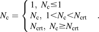
The substituting rules of N c to Eq. (1) are shown in Eq. (5), where N crt represents the upper limit of N c. It will be discussed below.
 $${N_{\rm{c}}} = \left\{ \matrix{ 1,\;{N_{\rm{c}}} \le 1 \hfill \cr {N_{\rm{c}}},\;1 \lt {N_{\rm{c}}} \lt {N_{{\rm{crt}}}} \hfill \cr {N_{{\rm{crt}}}},\;{N_{\rm{c}}} \ge {N_{{\rm{crt}}}} \hfill \cr} \right.\quad .$$
As a matter of fact, it has problem to consider N c like Eqs. (3) or (4). According to Eqs. (3)–(5), the bubble size will not be affected by the temperature when N c ≤ 1. It does not agree with the fact apparently. At the same time, when the gas is heated, the item containing Q in Eq. (1) also need be corrected. So, Eq. (6) is presented in this study, where the temperature affects the whole formula. And N c is determined by Eqs. (2) and (5). This modification agrees with the original physical meaning of N c, which reflects the amplification of the bubble volume because of the gas chamber. According to Park et al.,Reference Park, Tyler and Nevers11 the volume of the gas chamber affected the pressure fluctuation in the gas chamber and then affected the bubble volume. Only when the gas chamber volume was tiny, the smallest bubble could be produced. The smallest bubble volume just depended on the orifice diameter, the surface tension, and the liquid density. The parameter N c was presented to denote the ratio of the bubble's actual volume, with the existing of the gas chamber, to its potentially smallest volume.Reference Irons and Guthrie13 And N c had nothing to do with the temperature.
 $$D\prime = {\left[ {{{3{D_{\rm{o}}}\sigma } \over {g{\rho _{{\rm{lq}}}}}}\mathop {{N_{\rm{c}}}}\nolimits^m + {{\left( {{{9\mathop {{D_{\rm{o}}}}\nolimits^2 {\sigma ^2}} \over {{g^2}\mathop {{\rho _{{\rm{lq}}}}}\nolimits^2 }}\mathop {{N_{\rm{c}}}}\nolimits^{2m} + K{{{Q^2}{D_{\rm{o}}}} \over g}} \right)}^{1/2}}} \right]^{1/3}} \cdot {\left( {{{{T_{\rm{b}}}} \over {{T_{\rm{c}}}}}} \right)^{1/3}}\quad .$$
B. Critical gas chamber parameter N crt
Using Eq. (6) needs the value of N crt. Sano and MoriReference Sano and Mori12 found N crt = 9. However, Irons and GuthrieReference Irons and Guthrie13 found N crt >> 9. And Park et al.Reference Park, Tyler and Nevers11 proposed that N crt had a relationship with the orifice diameter.
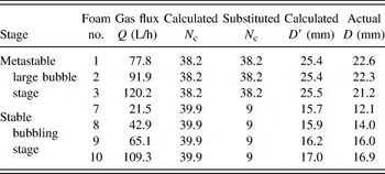
In our study, the gas flux has the dual-stage effect, and it was found that N crt in these two stages is different. For the foaming samples in Table II, the pore size calculated by Eqs. (2), (5), and (6) is shown in Table III. And the calculated and the substituted N c were also shown. During the calculation, D o = 0.6 mm, V c = 45 cm3 for no. 1 ∼ 3, V c = 47 cm3 for no. 7 ∼ 10, ρlq = 2400 kg/m3, g = 9.8 m/s2, P s = 101,325 Pa, σ = 0.9 N/m, T b = 943 K, T c = 300 K, m = 1, and K = 10. Seen from Table III, for the metastable large bubble stage, i.e., foam no. 1 ∼ 3, when the calculation of N c was substituted to Eq. (6), the results are closer to the actual values. However, for the stable bubbling stage, i.e., foam no. 7 ∼ 10, when N crt is 9, the results are more appropriate.
Substituted value of N c and calculated bubble size in different foaming processes.

According to Irons and Guthrie,Reference Irons and Guthrie13 when the wettability of the orifice is bad, N crt is much larger than 9. This study also reached a similar conclusion. In Sec. III. D, the wettability is considered to be worse in the metastable stage than in the stable stage. Seen from Table III, for the metastable stage, N crt is large. However, for the stable stage, N crt is about 9. It shows that, for the metastable stage, the influence of the gas chamber on the bubble size is big, while for the stable stage, the influence of the gas chamber is limited and the influence of the gas flux increases relatively.
C. Coefficient m and K
Using Eq. (6) also needs the values of m and K. Sano and MoriReference Sano and Mori12 found the values of m and K to be 1 and 10, but 0.816 and 10 according to Irons and Guthrie.Reference Irons and Guthrie13 As a semiempirical formula, the values of the two parameters depend on the experimental conditions strongly.
1. Correction coefficient in the metastable large bubble stage
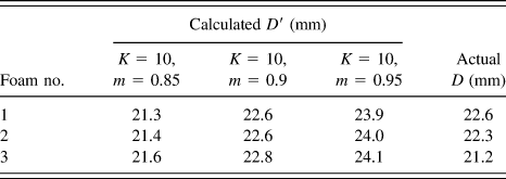
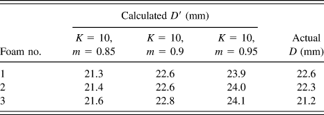
Seen from Table III, the calculation results of foam no. 1 ∼ 3 are larger than the actual values when m = 1 and K = 10. The new calculation results are listed in Table IV, when m = 0.85, 0.9, and 0.95, respectively, and K = 10. The other parameters for the calculation are the same as Table III. Seen from Table IV, it is appropriate that m = 0.9.
Effect of m on the pore size calculation in the metastable large bubble stage.
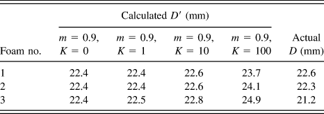
Some other new calculation results are listed in Table V, at m = 0.9 and K = 0, 1, 10, and 100 respectively. The other parameters for the calculation are the same as Table III. Seen from Table V, the value of K has little influence on the calculation. This is because in the metastable large bubble stage, the gas flux is small, and the value of N c is large. Compared with the gas chamber volume, the influence of the flux on the bubble size is relatively small. That is the reason why the pore size of foam no. 1 ∼ 3 does not change with the flux. Because the effect of K is little, it is possible to make K be 0 in the metastable stage.
Effect of K on the pore size calculation in the metastable large bubble stage.
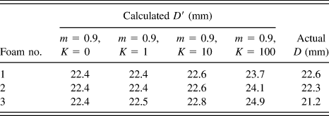
From above, m = 0.9 and K = 0. And there is no need to consider the upper limit of N c in the metastable large bubble stage, see Sec. IV. B. So, Eq. (6) can be simplified to Eq. (7).
 $$D\prime = {\left[ {{{6{D_{\rm{o}}}\sigma } \over {g{\rho _{{\rm{lq}}}}}}\mathop {{N_{\rm{c}}}}\nolimits^{0.9} } \right]^{1/3}} \cdot {\left( {{{{T_{\rm{b}}}} \over {{T_{\rm{c}}}}}} \right)^{1/3}},\;{N_{\rm{c}}} = \left\{ \matrix{ 1,\;{N_{\rm{c}}} \le 1 \hfill \cr {N_{\rm{c}}},\;{N_{\rm{c}}} > 1 \hfill \cr} \right.\quad .$$
2. Correction coefficient in the stable bubbling stage
It is easier to create small bubbles in the stable bubbling stage. Many experiments were carried in this stage, with the parameters as below: D o = 0.3–1.0 mm, V c = 0.34–104 cm3, Q = 10–120 L/h, and the foaming temperature 933–953 K.
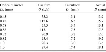
According to the experimental data, when m = 0.75 and K = 30, the calculation results agree well with the data. Their difference is less than ±2 mm. Part of the experiments and the calculations are listed in Table VI, where V c is 11 cm3 and other parameters for the calculation are the same as Table III. Compared with the metastable large bubble stage, m decreases and K increases in this stage. It shows that the effect of the gas chamber volume on the pore size is limited, and the effect of the gas flux increases.
Experiments and calculations in the stable bubbling stage.

From the above, in the stable bubbling stage, the pore size is calculated with Eq. (8).
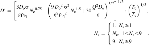 $$D\prime = {\left[ {{{3{D_{\rm{o}}}\sigma } \over {g{\rho _{{\rm{lq}}}}}}\mathop {{N_{\rm{c}}}}\nolimits^{0.75} + {{\left( {{{9\mathop {{D_{\rm{o}}}}\nolimits^2 {\sigma ^2}} \over {{g^2}{\rho _{{\rm{lq}}}}^2}}\mathop {{N_{\rm{c}}}}\nolimits^{1.5} + 30{{{Q^2}{D_{\rm{o}}}} \over g}} \right)}^{1/2}}} \right]^{1/3}} \cdot {\left( {{{{T_{\rm{b}}}} \over {{T_{\rm{c}}}}}} \right)^{1/3}},\;{N_{\rm{c}}} = \left\{ \matrix{ 1,\;{N_{\rm{c}}} \le 1 \hfill \cr {N_{\rm{c}}},\;1 \lt {N_{\rm{c}}} \lt 9 \hfill \cr 9,\;{N_{\rm{c}}} \ge 9 \hfill \cr} \right.\quad .$$
D. The effective gas chamber volume
Seen from Table I, by comparing foam no. 1 and no. 6, it is found that even though the gas flux through every orifice is almost the same, the pore size of the two foams is different. It is found that the orifice number has a division-effect not only on the gas flux but also on the gas chamber volume. The concept of the “effective gas chamber volume” is presented in this study, which denotes the nominal gas chamber volume divided by the effective orifice number. The pore size should be calculated by the “effective gas chamber volume,” not the nominal value.
For foam no. 4 ∼ 6, the effective gas chamber volume is used to calculate the pore size as Eq. (7). During the calculation, Q was substituted by the quarter of the total flux and the other parameters are the same as Table III. The calculation result is 14.8 mm, which agrees with the experimental data. To get small bubbles, the effective gas chamber volume should be as small as possible, especially for the metastable large bubble stage.
The foam no. 1 ∼ 6 in Table I is generated in the “metastable large bubble stage”. In this stage, the effect of the orifice number on the bubble size is apparent. In fact, the number determines the “effective gas chamber volume” which has larger influence on the “metastable large bubble stage” than on the “stable bubbling stage” (see Sec. IV. B). So we select the metastable stage to show the effect of the orifice number.
V. CONCLUSIONS
(1) In the gas injection foaming process, the bubble size decreases with the decreasing of the orifice diameter for the wetted nozzle.
(2) The bubble size decreases with the decrease of the gas chamber volume and the increase of the orifice number. The effective gas chamber volume, which is the nominal gas chamber volume divided by the effective orifice number, can characterize the effect of the two parameters. To get the small bubbles, the effective gas chamber volume should be as small as possible.
(3) The effect of the gas flux on the bubble size has a dual-stage. If the flux is always small during the process, the foaming is in the “metastable large bubble stage”. At this time, the bubbles are large and their size is affected mostly by the gas chamber volume, not the flux. When the flux increases to some certain value, the bubbles decrease suddenly, and the foaming comes into the “stable bubbling stage”. At this time, bubble size changes with the flux apparently and is smaller than the one in the metastable stage under the same flux. However, the influence of the gas chamber volume is limited in this stage. To get small and controllable pores, the foaming should be in the stable bubbling stage.
(4) The pore size can be calculated by a modified formula, where the foaming temperature affects the whole formula. For the metastable large bubble stage, m = 0.9, K = 0, and the upper limit of the gas chamber parameter, N crt, is ignored. That is to say, the influence of the gas flux is ignored, and the calculated value of N c can be substituted directly. For the stable bubbling stage, m = 0.75, K = 30, and N crt = 9.
ACKNOWLEDGMENT
The authors gratefully acknowledge the help from Ms. Fan Xueliu and Mr. Zhang Huiming.
VI. NOTATION
(For calculation, the International System of Units is needed.)
- D
the measured mean pore size of the aluminum foam, replacing the bubble size, m.
- D′
the calculated bubble size, m.
- D o
the inner diameter of the nozzle orifice, m.
- g
the acceleration of gravity, 9.8 m/s2.
- K
the correction coefficient for the effect of the flux in bubble size formula.
- L
the mean intercept for measuring the mean pore size, m.
- m
the correction coefficient for the effect of the gas chamber volume in bubble size formula.
- N c
the gas chamber parameter.
- N crt
the upper limit of the gas chamber parameter N c.
- P
the gas pressure, Pa.
- P Q
the relative gas pressure near the flow meter, Pa.
- P s
the static pressure, 101,325 Pa in this study.
 ${P_{{V_{\rm{c}}}}}$
the relative gas pressure in the gas chamber, Pa.
- Q
the gas flux under 101,325 Pa and 293.15 K, m3/s.
- T c
temperature in the gas chamber, K.
- V c
gas chamber volume, m3.
- σ
surface tension of the liquid, N/m.
- ρlq
density of the liquid, kg/m3.