

DISCUSSION POINTS
-
• Is methanol a renewable fuel for the future?
-
• Can you imagine powering your laptop computer with alcohol?
-
• What will be the role of fuel cells versus batteries in the future energy economy?
Introduction
Globally, around 90% of the transport sector depends on fossil fuel powered internal combustion engines (ICEs). Reference Van Vilet, Brouwer, Kuramochi, van den Broek and Faaij1 While this technology has enabled an unprecedented increase in human mobility, the consumption of fossil fuels by the transport sector has also greatly contributed to the atmospheric emission of greenhouse gases (mainly carbon dioxide) and other pollutants, such as nitrogen oxides (NO x ) and volatile organic compounds (VOCs). Reference Dunn2,3 Besides these environmental concerns, fossil fuels are considered to be unsustainable in the long-term as they represent a finite resource fraught with geopolitical constraints and increasing costs of extraction. Reference Bent, Orr and Baker4 Because of these factors, a number of alternative, sustainable energy solutions are under active development.
Among potential long-term solutions, fuel cells based on potentially renewable fuels, such as hydrogen and methanol have received considerable attention. Reference Wang, Chen, Mishler, Cho and Adroher5–Reference Chan7 In the portable power and transportation sector, polymer electrolyte membrane fuel cells (PEMFCs) have been the major focus, as they provide higher power density and more facile cycling performance than other fuel cell archetypes. In the transportation arena, PEMFCs can extract significantly more power out of the same quantity of fuel when compared to traditional combustion engines, thereby providing 30–90% higher efficiency (on a “well-to-wheels” basis) than regular gasoline-powered ICEs. 8 Most vehicular fuel cells are based on hydrogen-powered PEMFC technology. However, the commercialization of hydrogen-powered PEMFC vehicles suffers from challenges due to on-board storage constraints (even at 1000 bar, H2 takes up about 3000 times more space than an equivalent amount of gasoline), and lack of a consumer H2 distribution infrastructure. Reference Ogden, Steinbugler and Kreutz9,Reference Armaroli and Balzani10
The leading direct liquid fuel PEMFC technology, known as the direct methanol fuel cell (DMFC), produces electric power directly from high energy density liquid methanol fuel. Deploying DMFC in the vehicles can resolve on-board storage constraints, as liquid methanol fuel can be distributed using the existing gasoline distribution infrastructure with only minor modifications. Reference Dillon, Srinivasan, Arico and Antonucci11,Reference McNicol, Rand and Williams12 Despite this advantage, the higher materials fabrication cost and the typical lower efficiency and power density of DMFCs pose daunting barriers for the deployment of DMFC technology in the transportation sector. Weighing in favor of DMFC technology, however, the transition to a methanol-powered transportation sector could be accomplished through a series of more incremental steps compared to the significant infrastructure investments needed for a future H2-powered transportation sector. For example, methanol might first be introduced into the existing ICE-based transportation sector by means of blending methanol with gasoline for flex fuel vehicles (FFV). The FFV scenario is intriguing considering the recent abundance of inexpensive natural gas, which has rendered methanol competitive with gasoline under large-scale production scenarios. Couple that with the fact that methanol has a higher octane value and is less toxic than gasoline Reference Aricò, Baglio and Antonucci13,Reference Basak, Kausshik and Biswas14 and the case for methanol blended gasoline FFV gains strength.
Methanol is less expensive (per unit energy) and provides significantly higher volumetric and gravimetric energy density compared to compressed hydrogen (at 1000 bar) or even compared to liquid hydrogen. Reference Aricò, Baglio and Antonucci13,Reference Basak, Kausshik and Biswas14 Interestingly, one liter of methanol contains more hydrogen (99 g) than a liter of liquid hydrogen (71 g). Reference Basak, Kausshik and Biswas14
Methanol can be produced by a number of methods. Methanol is mostly obtained from feedstocks such as coal and natural gas by means of the gasification and steam reforming processes, respectively. Reference Olah, Goeppert and Prakash15,Reference Nichols16 In recent years, interest has grown in producing methanol from renewable energy sources such as wood, agricultural wastes, and other biomass resources by thermochemical processes. Such processes produce around 170 gallons of methanol per ton of biomass. Reference Nichols16 While methanol production from coal and biomass is less efficient than from natural gas (50–60% compared to 70–80% efficiency), the renewable nature of biomass feedstock coupled with the possibility for improving production efficiency makes methanol production from biomass an attractive long-term solution. But production of methanol from biomass raises some concern over the possibility of crop displacement, which could become a serious issue. Reference Mitchell17
Here, it is interesting to recall the opinion of Dr. George A. Olah, winner of the 1994 Nobel Prize in chemistry, who stated that “methanol in its own right is an excellent fuel in liquid form as it can be mixed with gasoline in any proportion, easily stored, transported and can be considered as a universal energy carrier that could eventually replace all the hydrocarbons and ethanol.” Reference Olah, Goeppert and Prakash15 Once established, a methanol transportation sector could be further enhanced by the introduction of DMFC-powered vehicles, which would yield environmental, efficiency, and associated operating-cost advantages compared to combustion-based methanol-fueled vehicles. Thus, the attractive properties of methanol in terms of its energy density, ease of distribution, and potential for production from clean fossil-based resources (natural gas) or from renewable sources (biomass, solar) make the DMFC an intriguing, although still far-off transportation power technology. Reference Bromberg and Cheng18–Reference McGrath, Prakash and Olah20
Because of the daunting cost, durability, and power-density issues impeding the application of DMFC to the transportation sector, it is likely that DMFC technology will first be commercialized for small portable power applications (e.g., the displacement of batteries in consumer electronic applications), where the shorter product lifetimes (∼1–2 years for a battery versus 8–15 years for a car) and the much higher price points (∼$10/W for a laptop battery versus ∼$0.05/W for a vehicle) provide a more attractive entry point. Reference Colpan, Dincer, Hamdullahpur, Kakac, Pramuanjaroenkij and Vasiliev21,Reference Garche, Stimming, Friedrich, Feidenhans'l, Garche, Stimming, Friedrich, Feidenhans'l, Sønderberg Petersen and Sønderberg Petersen22 In fact, a number of organizations are actively developing DMFCs for portable electronics devices such as cell phones and laptop computers. Reference Jung, Jo, Jung, Cho, Kim and Shin23–Reference Hockaday25 While such applications are not likely to significantly impact the global energy sustainability picture, they provide an important initial market for fuel cell technology. As such, in this review, we provide an overview of current methanol-based FC technologies and applications, recent research and development, and the challenges to their commercialization for both the portable (shorter-term) and transport (longer-term) sectors.
Concept and principles of DMFC
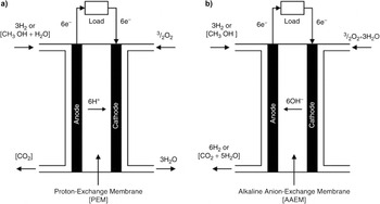
Figure 1 illustrates the basic operating principles of both acid- and alkaline-based DMFCs. Reference Slade, Kizewski, Poynton, Zeng, Varcoe and Kreuer26 In a DMFC, the key component is the membrane electrode assembly (MEA), in which anode and cathode catalyst layers are in intimate contact on either side of the polymer electrolyte membrane (PEM) (either acid or alkaline based membranes can be used). Conventionally, carbon-supported PtRu or (unsupported) PtRu black catalysts are used in the anode and carbon-supported Pt or Pt black catalysts are used in the cathode. Gas diffusion layers (GDLs) are placed in intimate contact with the catalyst layers to aid reactant distribution, current collection, and catalyst-layer protection. GDLs are typically made by coating a carbon and polytetrafluoroethylene (Teflon) mixture on the catalyst-facing-side of a carbon paper/cloth. The presence of Teflon in the GDLs exerts hydrophobic properties necessary to transport oxygen molecules to the catalytic sites at the cathode or to facilitate the escape of CO2 from the anode.
(a) Principles involved in the operation of acid and (b) alkaline based DMFCs. Reproduced with permission from Springer Science, Copyright 2013. Reference Slade, Kizewski, Poynton, Zeng, Varcoe and Kreuer26

In the DMFC, a methanol/water mixture is directly fed to the anode. Methanol is directly oxidized to carbon dioxide with the possible formation of intermediate species such as carbon monoxide, formaldehyde, and/or formic acid. The formation of these intermediate species is held responsible for the sluggish kinetics of the methanol oxidation reaction (MOR) in the anode. Reference Iwasita, Vielstich, Lamm and Gasteiger27 The protons produced during the MOR conduct from the anode to the cathode through the Nafion membrane, while the produced electrons flow from the anode to cathode through an external circuit as shown in Fig. 1. The electrons and protons react with oxygen molecules at the cathode and produce water. In the case of an alkaline DMFC, the methanol is oxidized by OH− ions that are conducted from the cathode to the anode through the alkaline membrane and water is therefore produced at the anode instead.
The overall reaction process that occurs in an acid-based DMFC is shown below:
Anode reaction:
 $${\rm{C}}{{\rm{H}}_3}{\rm{OH}} + {{\rm{H}}_2}{\rm{O}} \to {\rm{C}}{{\rm{O}}_2} + 6{{\rm{H}}^ + } + 6{{\rm{e}}^ - }.$$
Cathode reaction:
 $${3 \mathord{\left/ {\vphantom {3 2}} \right. \kern-\nulldelimiterspace} 2}{{\rm{O}}_2} + 6{{\rm{H}}^ + } + 6{{\rm{e}}^ - } \to 3{{\rm{H}}_2}{\rm{O}}{\rm{.}}$$
Overall reaction:
 $${\rm{C}}{{\rm{H}}_3}{\rm{OH}} + {3 \mathord{\left/ {\vphantom {3 {\rm{2}}}} \right. \kern-\nulldelimiterspace} {\rm{2}}}{{\rm{O}}_{\rm{2}}} \to {\rm{C}}{{\rm{O}}_2} + 2{{\rm{H}}_2}{\rm{O}}.$$
In the case of an alkaline-based DMFC, the reaction process is shown below:
Anode reaction:
 $${\rm{C}}{{\rm{H}}_3}{\rm{OH}} + 6{\rm{O}}{{\rm{H}}^ - } \to {\rm{C}}{{\rm{O}}_2} + 5{{\rm{H}}_2}{\rm{O}} + 6{{\rm{e}}^ - }.$$
Cathode reaction:
 $${{\rm{3}} \mathord{\left/ {\vphantom {{\rm{3}} {\rm{2}}}} \right. \kern-\nulldelimiterspace} {\rm{2}}}{{\rm{O}}_{\rm{2}}}{\rm{ + 3}}{{\rm{H}}_{\rm{2}}}{\rm{O + 6}}{{\rm{e}}^ - } \to {\rm{6O}}{{\rm{H}}^ - }.$$
Overall reaction:
 $${\rm{C}}{{\rm{H}}_3}{\rm{OH}} + {3 \mathord{\left/ {\vphantom {3 {\rm{2}}}} \right. \kern-\nulldelimiterspace} {\rm{2}}}{{\rm{O}}_{\rm{2}}} \to {\rm{C}}{{\rm{O}}_2} + 2{{\rm{H}}_2}{\rm{O}}.$$
The free energy change, ΔG, associated with the overall reaction can be directly related to the reversible cell potential via:
 $$\Delta G = - nFE,$$
where n is the number of electrons involved in the chemical reaction (n = 6 electrons per mole of methanol), F is the Faraday constant (96,487 coulombs per mole), and E is the equilibrium (reversible) cell potential.
DMFC polarization curves, efficiency, and energy density
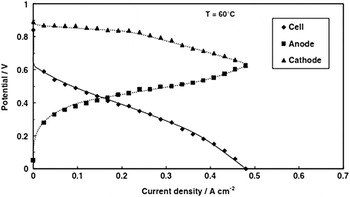
In most DMFCs, the open circuit voltage (OCV) is significantly lower than the reversible potential. This is mainly attributed to the factors such as the irreversible adsorption of methanol-derived intermediate species at the anode and methanol crossover from anode to cathode. These effects lead to a mixed potential at the cathode, thereby reducing the OCV to values typically lower than 0.9 V (versus a reversible potential of 1.22 V). Reference Ren, Wilson and Gottesfeld28–Reference Shukla, Christensen, Hamnett and Hogarth30 The reversible potential falls below 0.9 V in the presence of even a small amount of methanol crossing through the membrane from the anode. As current is drawn from the cell, the cell voltage decreases further due to the combined effect of kinetic overpotentials, ohmic losses, and mass transport constraints due to the CO2 gas removal from anode and flooding at the cathode (see Fig. 2). Reference Jiang, Rong and Chu31
DMFC single cell, anode, and cathode polarization curves operated at 60 °C, ambient pressure, with 1M methanol and air feed at the anode and cathode, respectively. Reproduced with permission from Wiley-VCH, Copyright 2009. Reference Aricò, Baglio and Antonucci13

As it is possible to separately measure the anode and cathode potentials using a dynamic hydrogen electrode (DHE), the typical polarization responses for both electrodes (E cathode, E anode), as well as the overall cell polarization curve (E cell) are shown in Fig. 2.
 $${E_{{\rm{cell}}}} = {E_{{\rm{cathode}}}} - {E_{{\rm{anode}}}}.$$
In contrast to PEMFCs, where most of the overall cell polarization can typically be attributed to the cathode, in DMFCs both the anode and cathode contribute significantly to the overall cell polarization.
DMFC efficiency
For all fuel cells, including DMFCs, the voltage efficiency is determined by the ratio between the terminal cell voltage and the reversible potential for the process during the operation of the fuel cell at the same temperature and pressure.
 $${\eta _{\rm{v}}} = {{{E_{{\rm{cell}}}}} \mathord{\left/ {\vphantom {{{E_{{\rm{cell}}}}} {{E_{{\rm{rev}}}}}}} \right. \kern-\nulldelimiterspace} {{E_{{\rm{rev}}}}}},$$
where ηv is the voltage efficiency, E cell is the operating cell voltage, and E rev is the theoretical cell voltage. Because of the methanol crossover issue in most DMFCs, not all of the methanol consumed by the cell is converted into electrical current. A fuel efficiency parameter (ηf) can therefore be defined as the ratio between the measured electrical current (I) and that calculated from Faraday's law on the basis of methanol consumption (I total):
 $${\eta _{\rm{f}}} = {I \mathord{\left/ {\vphantom {I {{I_{{\rm{total}}}}}}} \right. \kern-\nulldelimiterspace} {{I_{{\rm{total}}}}}}.$$
The overall efficiency of the DMFC can then be expressed as
 $$\eta = {\eta _{{\rm{rev}}}} \times {\eta _{\rm{v}}} \times {\eta _{\rm{f}}},$$
Where ηrev accounts for irreversible entropic losses and is generally defined as:
 $${\eta _{{\rm{rev}}}} = {{\Delta G} \mathord{\left/ {\vphantom {{\Delta G} {\Delta H}}} \right. \kern-\nulldelimiterspace} {\Delta H}},$$
where ΔG and ΔH are the Gibbs free energy and enthalpy of the overall MOR, respectively.
It has been shown that in a DMFC at 0.5 V and with 97% fuel utilization, the overall chemical to electrical conversion efficiency will be around 40%. Reference Gao, Abeysiri and Winfield32 Moore et al. Reference Moore, Gottesfeld and Zelenay33 obtained a maximum conversion efficiency around 35% for a single cell DMFC using 1M methanol in a careful study where the methanol crossover current density was measured along with cell current density and voltage. Most published efficiency metrics pertain to DMFC single cells. Efficiency information for complete DMFC systems is generally not available, but should be lower than single-cell metrics due to additional power losses associated with system ancillaries.
Energy density of methanol
The energy density of a fuel can be defined with respect to weight (kWh/kg) or volume (kWh/L) as
 $${W_{\rm{e}}} = \left( {{{ - \Delta H} \mathord{\left/ {\vphantom {{ - \Delta H} {3600M}}} \right. \kern-\nulldelimiterspace} {3600M}}} \right)\;{\rm{or}}\;{W_{\rm{s}}} = \left( {{{ - \Delta H\rho } \mathord{\left/ {\vphantom {{ - \Delta H\rho } {3600M}}} \right. \kern-\nulldelimiterspace} {3600M}}} \right),$$
where W e and W s are the theoretical specific energy (Wh/g) and specific energy density (Wh/L), respectively; ΔH is the molar heat of combustion (kJ/mol) of the fuel; M is the molecular weight (g/mol) of the fuel, and ρ is the density (g/L) of the fuel.
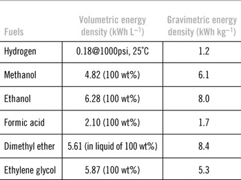
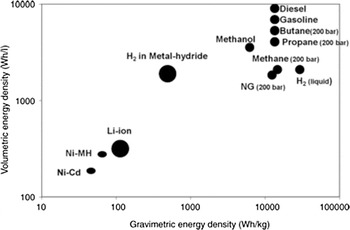
Table 1 and Fig. 3 summarize the energy density of various fuels. From the figure and table, it is apparent that pure methanol has an energy density 15 times higher than the energy density of a Li-ion battery and is one order of magnitude larger than H2 stored in a pressurized tank (at 200 bar) or in a metal hydride system (4–5%). But, the energy density of methanol is lower than that of conventional liquid fuels such as gasoline and diesel.
Volumetric and gravimetric energy density for various fuels for low-temperature fuel cells. (Reproduced with permission from Wiley-VCH, Copyright 2009. Reference Aricò, Baglio and Antonucci13 )

Gravimetric and volumetric energy density of various fuels and batteries. Reproduced with permission from Wiley-VCH, Copyright 2009. Reference Aricò, Baglio and Antonucci13

Although the theoretical volumetric and gravimetric energy density values of methanol are clearly much higher than the energy density of the battery systems shown in Fig. 3, this is somewhat of an unfair comparison. The net energy density of a complete DMFC system will be much lower than the energy density of neat methanol fuel due to the mass/volume of the system components and the low (25–35%) conversion efficiency of methanol in DMFCs. Reference Shah and Besser34 Nevertheless, recent comparisons of actual Li-ion batteries (with conversion efficiency of above 80%) and a real DMFC system showed the DMFC to have more than twice the gravimetric energy density (130–200 Wh kg−1 for the Li-ion batteries, versus 400 Wh kg−1 for the DMFC). Reference Hebling35,Reference Florez and Adolp36
State-of-the-art anode, cathode, and electrolyte materials for DMFC
Anode catalysts
Until now, Pt-based noble metal catalysts remain the best choice for activating the MOR at the DMFC anode. When using a pure Pt catalyst, the MOR is not completely realized because of the formation and subsequent irreversible absorption of CO and CHO intermediate species, Reference Beden, Kadirgan, Lamy and Leger37–Reference Prabhuram and Manoharan39 which severely impede the kinetics of methanol oxidation on Pt. To mitigate the effect of these poisonous species, the Pt catalyst is usually alloyed with second metals such as Ru, Sn, Mo, Co, Ni, etc. It has been proposed that these second metals alleviate the irreversible absorption of the poisoning intermediate species by means of the bifunctional mechanism and the ligand effect. Reference Watanabe and Motoo40,Reference Goto, Li, Senoo, Noda, Kudo, Maesaka and Hatazawa41 The bifunctional mechanism involves the oxidation of CO/CHO intermediates adsorbed on Pt by OHads species formed on the second metal at a relatively lower anodic potential. Reference Watanabe and Motoo40 The ligand effect involves a decrease in the adsorption energy of CO/CHOads species on Pt due to alloying with the second metal, thereby facilitating the oxidation of these poisonous species at relatively lower anodic potential. Reference Goto, Li, Senoo, Noda, Kudo, Maesaka and Hatazawa41 Extensive studies of the MOR in both acid and alkaline media on various Pt-based bimetallic catalysts (PtRu, PtMo, PtW, and PtSn) have shown that PtRu catalysts exhibit the highest MOR activity Reference Gotz and Wendt42–Reference Prabhuram and Manoharan44 as well as higher DMFC power density and stability compared with other bimetallic catalysts. Ruthenium dissolution, however, poses a big issue in PtRu catalyst systems. Reference Gotz and Wendt42,Reference Zhou, Zhou, Li, Zhou, Song, Sun, Xin, Douvartzides, Goula and Tsiakaras45–Reference Lizcano-Valbuena, Bortholin, Neto, Paganin and Gonzalez49
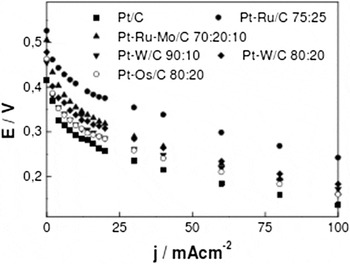
In analogy to common practice in PEMFCs, DMFCs often use supported PtRu catalysts, where nanoscale PtRu catalyst particles are supported on a high surface area carbon powder to increase mass activity and therefore bring down the cost compared to using an unsupported PtRu black catalyst. Lizcano-Valbuena et al. Reference Lizcano-Valbuena, Bortholin, Neto, Paganin and Gonzalez49 compared various types of carbon-supported Pt-based alloys for the anode of the acid-based DMFC and showed that PtRu/C (75:25 by weight) provided the best performance among the various Pt-based alloys as depicted in Fig. 4.
Voltage versus current density plot for a single cell of the DMFC using various types of carbon-supported Pt-based alloys. Reproduced with permission from The Electrochemical Society, Copyright 2001. Reference Lizcano-Valbuena, Bortholin, Neto, Paganin and Gonzalez49

Further research on reducing the loading level of PtRu on the supporting material while at the same time maintaining performance and stability is needed. To improve DMFC catalyst performance and stability, various types of carbon supports have been explored. Reference Salgado, Paganin, Gonzalez, Montemor, Tacchini, Anson, Salvador, Ferreira, Figueiredo and Ferreira50–Reference Bong, Kim, Kim, Woo, Uhm, Lee and Kim54 PtRu supported on carbon nanofibres, carbon nanotubes, and graphenes have exhibited particularly intriguing DMFC performance and stability. Reference Prabhuram, Zhao, Tang, Chen and Liang52,Reference Bong, Kim, Kim, Woo, Uhm, Lee and Kim54,Reference Kang, Lim, Peck, Kim, Jung, Hong, Jung and Shul55 Several researchers have also explored chemically modifying the carbon support itself as a means to improve catalyst performance and stability. Reference Zhou, Neyerlin, Olson, Pylypenko, Bult, Dinh, Gennett, Shao and O'Hayre56–Reference Olson, Dameron, Wood, Pylpenko, Hurst, Christensen, Bult, Ginley, O’Hayre, Dinh and Gennett60 Of particular note, PtRu catalysts impregnated/deposited on nitrogen modified carbon supports have been shown to exhibit significantly higher performance and stability when compared to undoped counterparts. Reference Corpuz, Olson, Joghee, Pylypenko, Dameron, Dinh, O'Neill, Hurst, Bender, Gennett, Pivovar, Richards and O'Hayre61–Reference Corpuz, Wood, Pylypenko, Demeron, Joghee, Olson, Bender, Dinh, Gennett and Richards63
Cathode catalysts
In the cathode of a DMFC, as in a PEMFC, Pt metal remains the best catalytic material even though Pt suffers a nearly 400 mV loss due to the sluggish electrochemical kinetics of the oxygen reduction reaction (ORR) and mixed potential caused by methanol crossover. Reference Ralph and Hogarth64–Reference Casalegno, Bresciani, Zago and Marchesi66 In commercial DMFC systems, carbon-supported Pt is used at the cathode to minimize the cost.
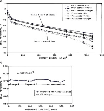
To improve the kinetics of the ORR and improve the tolerance against methanol crossover, various carbon-supported Pt-based alloys (Pt–M, where M is Fe, Au, Pd, Cr, and W2C) have been developed for the cathode and these alloys show improved performance in DMFCs versus pure Pt/C catalysts. Reference Li, Xin and Yan67–Reference Meng, Shen, Wei and Jiang71 It has been proposed that the formation of Pt-based alloys slightly decreases the Pt–Pt interatomic distance, facilitating cleavage of the strong O=O bond of oxygen to achieve the complete oxygen reduction that favors 4 electron transfer. Reference Ralph and Hogarth64,Reference Meng, Shen, Wei and Jiang71 The stability of the PtCr and PtFe alloys has been studied in PEMFC cathodes, Reference Antolini, Salgado and Gonzalez72–Reference Xiong and Manthiram74 and the findings suggest that the stability of these alloys depends on the degree of alloying as well as the catalyst particle size. For instance, Ballard Inc. has demonstrated enhanced initial performance and better durability (over 500 h) for PtCr catalysts compared to Pt catalysts in PEMFC cathodes (see Fig. 5). Reference Ralph and Hogarth64
(a) Comparative performance of Pt and PtCr alloys in PEMFC cathodes operating at 80 °C using hydrogen/air, hydrogen/helox (helox is a mixture of helium and oxygen), and hydrogen/oxygen at 1.5/2 and 2/10 anode/cathode stoichiometry (308/308 kPa anode/cathode pressure). (b) Durability test for Pt and PtCr alloys under the same temperature and pressure conditions as (a) using hydrogen/air at 1.5/2 stoichiometry. Reproduced with permission from Johnson Matthey, Copyright 2002. Reference Ralph and Hogarth64

To lower cost, it is highly desirable to develop non-noble metal alternatives to Pt-based catalysts. Potential alternatives include pyrolysed Fe porphyrins and Ru-based chalcogenides, which show decent ORR performance (although still not competitive with Pt) and excellent methanol tolerance. Reference Reeve, Christensen, Hamnett, Haydock and Roy75,Reference Sun, Wang and Savinell76 However, long-term stability is a potential issue with many of these catalysts and further breakthroughs are needed. In alkaline media, because of a wider range of stable metal alloys and inherently faster ORR kinetics, less expensive metals such as Pd, Ag, and their alloys have been successfully used as carbon-supported cathode catalysts with reasonable performance and comparable stability to Pt/C catalysts. Reference Bunazawa and Yamazaki77–Reference Okajima, Nabekura, Kondoh and Sudoh80 Current intensive research on Pd and Ag and their alloys for the ORR in alkaline media provides further hope that these metals could provide a lower-cost alternative to Pt and Pt-based alloys for alkaline-based PEMFC and DMFC cathodes.
Electrolyte materials
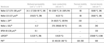
The desired traits for a PEM in a DMFC application include: (i) stable high temperature (80–90 °C) operation capability, (ii) low methanol crossover (<10−6 mol min−1 cm−1) or low diffusion coefficient of the membrane (<5.6 × 10⁻⁶ cm2 s−1 at T = 25 °C), Reference Arico, Srinivasan and Antonucci81 (iii) high ionic conductivity (>80 mS cm−1), Reference Arico, Srinivasan and Antonucci81 (iv) high chemical and mechanical durability particularly at T > 80 °C, (v) low ruthenium crossover, and (vi) low cost. The most commonly used cation exchange membrane (CEM) in DMFCs is Dupont's Nafion membrane, which does not satisfy all the above requirements due to disadvantages including high cost ($600–$1200 m−2), Reference Agro, DeCarmine, DeFelice and Thoma82 high cost per unit power (300 $ kW−1 at 240 mW cm−2), Reference Howell83 high methanol crossover, Reference Reeve84 and high ruthenium crossover from anode to cathode. Reference Piela, Eickes, Brosha, Garzon and Zelenay85 Despite these disadvantages, however, alternative membranes generally do not match the performance and durability of Nafion, which therefore remains the membrane of choice for most commercial DMFC applications. In the search for better membranes, researchers have pursued the modification of Nafion-type membranes as well as the development of entirely new classes of membranes. Reference Antonucci, Arico, Creti, Ramunni and Antonucci86–Reference Wang, Wainright, Savinell and Litt91 While many of these newer membranes are lower in cost than Nafion, they have generally not yet obtained the combination of high conductivity and high stability that makes Nafion so compelling. The characteristic properties of various CEM types along with their DMFC performance are provided in Table 2.
Properties of various types of CEMs for application in DMFC.

a At higher fuel cell operating temperature (above 80 °C), Nafion type membranes are likely to lose water and mechanical strength, which may have a detrimental effect on the performance/durability of the fuel cell. Additives like SiO2 and ZrP can be added to enhance the thermal stability of Nafion as they can help to retain water and mechanical strength even at higher fuel cell operating temperature (above 100 °C).
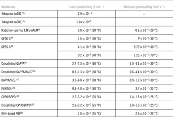
In contrast to CEMs, anion exchange membranes (AEMs) are solid PEMs that contain positive ionic groups (typically quaternary ammonium functional groups such as poly-N+Me3) and mobile OH− ions. They are also commonly referred to as alkaline membranes. Some of the commercially available AEMs for DMFC application include MORGANE-ADP and an ammonia-based AEM membrane from Tokuyama Co. Japan. Interestingly, these AEMs exhibit low methanol crossover because of the absence of electro-osmotic drag from the anode side: the OH− ions migrate from cathode to anode in alkaline-based DMFCs, whereas in CEMs, protons migrate from the anode to the cathode and tend to drag methanol molecules with them. Unfortunately, however, the diffusion coefficient and ionic mobility of OH− are typically less than H+ so AEMs tend to show lower conductivities. Most AEMs are also not as stable as their CEM counterparts at elevated operating temperatures. Reference Yu and Scott94,Reference Yu, Krewer and Scott95 The development of AEMs with high ionic conductivity, good chemical stability, and low methanol permeability is an area of active research. Reference Yu, Krewer and Scott95–Reference Hou, Sun, He, Sun, Jin, Liu and Xin105 The basic properties of several widely investigated AEMs are given in Table 3.
Basic properties of various types of AEMs for DMFC application.

MEA fabrication
DMFC performance and durability mainly rely on the structure of the MEA, which is the key component in the DMFC. In recent years, many attempts have been made to improve the fabrication process and structural parameters of the MEAs to maximize the number of triple-phase boundaries available to facilitate the electrochemical reaction. Conventional methods to fabricate the MEAs are classified into two groups. Reference Lindermeir, Rosenthal, Kunz and Hoffmann106–Reference Zhang, Yin, Wang and Shao108 One is the catalyst-coated substrate (CCS) method and the other is the catalyst-coated membrane (CCM) method. In the CCS approach, the anode and cathode catalysts are coated on the GDL, which is made of carbon paper, felt, or cloth, and subsequently hot pressed by sandwiching the membrane electrolyte in-between the anode and cathode catalyst-coated GDLs to form the MEA. In this method, the catalyst layer coated on the GDL is not always effectively transferred to the membrane and some of the catalytic particles get buried into the GDL and are not effectively utilized for the electrochemical reaction during fuel cell operation. Therefore, this method may not be suitable for achieving high MEA performance.
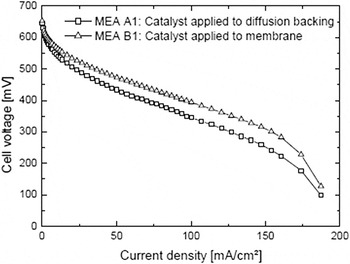
In the CCM method, the anode and cathode catalysts are directly coated on the two sides of the membrane and the GDLs are subsequently sandwiched on either side. In this approach, hot-pressing of the GDL is usually not required. Reference Zhang, Yin, Wang and Shao108 The catalyst thickness can be controlled and the interfacial contact between the membrane and the catalyst layer is found to be very intimate due to the direct coating of the catalyst layer on the membrane. This helps to achieve higher cell performance. Reference Pak, You, Choi and Chang109 The DMFC performance of the MEAs fabricated by the CCS (or catalyst coated on diffusion backing) and CCM method is shown in Fig. 6. Reference Lindermeir, Rosenthal, Kunz and Hoffmann106
Polarization curves of MEA1 (catalyst loading anode/cathode = 1/1 mgPt cm−2) and MEA2 (catalyst loading anode/cathode = 1/1 mgPt cm−2). Conditions: T = 80 °C, CMeOH= 0.75M, O2 operation, cathode/anode overpressure =0.1/0 bar. Reproduced with permission from Elsevier, Copyright 2004. Reference Lindermeir, Rosenthal, Kunz and Hoffmann106

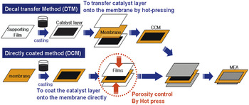
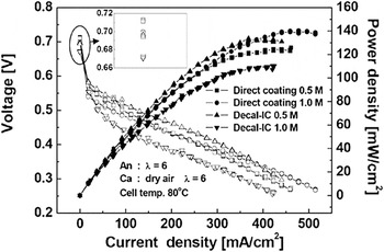
An alternative approach called the decal transfer method (DTM) has also been adopted to achieve higher cell performance and mass production of MEAs. Reference Cho, Kim, Prabhuram, Hwang, Ahn, Ha and Kim110 In the DTM approach, the catalyst layers are deposited on Teflon decal substrates and are then subsequently transferred to a dry electrolyte membrane during the hot-pressing of the MEA. MEAs fabricated by the CCM and DTM methods have an improved catalyst/membrane interface, better catalyst utilization, Reference Zhang, Yin, Wang and Shao108,Reference Cho, Kim, Prabhuram, Hwang, Ahn, Ha and Kim110 and superior formation of the ionomer network. Reference Tang, Wang, Pan, Jiang and Ruan107,Reference Cho, Kim, Prabhuram, Hwang, Ahn, Ha and Kim110 These aspects are all generally beneficial in improving the performance and durability of a DMFC used with both acid- and alkaline-based membranes. Reference Joghee, Pylypenko, Wood, Bender and O'Hayre48,Reference Cho, Kim, Prabhuram, Hwang, Ahn, Ha and Kim110 The CCM and DTM MEA fabrication processes are compared in Fig. 7. Reference You, Lee, Cho, Kim, Pak, Lee, Park and Park111
Schematic comparison of the CCM and DTM MEA fabrication processes. Reproduced with permission from International Journal of Hydrogen Energy, Copyright 2011. Reference You, Lee, Cho, Kim, Pak, Lee, Park and Park111

History of research on DMFC performance and long-term stability
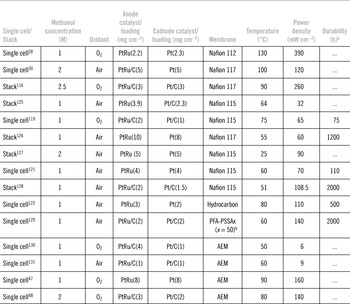
Basic investigations into the direct electro-oxidation of methanol were initiated in the early to mid 1980s. During these early years, research focused on the development of suitable anode and cathode electrocatalysts and characterization of their performance in half-cell configurations with aqueous acid or alkaline electrolytes. Reference Iwastia and Vielstich112–Reference Kordesch and Simader114 DMFC research increased significantly in the 1990s, with the development of DMFC MEAs and the proliferation of single cell and DMFC stack/system studies. This section will focus on MEA and stack-level studies from the early 1990s to the current period. Table 4 summarizes some of the performance and durability data.
Performance and durability of single cell and stacks of DMFC.

a DMFC durability measurement is not standardized. Typically, either constant-current or constant-voltage durability tests are used. In Refs. Reference Liu, Zhou, Zhao, Xin, Sun and Yi119 and Reference Wang, Rivera, Wang, Zhang, Feng, Lewis and Smotkin121, a constant voltage 0.4–0.5 V (per single cell) was used for durability testing (which normally yields a current density of around 100–150 mA cm−2). In the other studies, Reference Kang, Jung, Shin, Lim, Kim, Shul and Peck129–Reference Kim, Shin, Park, Song and Kim132 durability was evaluated under a constant current density mode of 100–150 mA cm−2 (which generally yields a voltage of around 0.4–0.5 V). The voltage and current-based durability studies chosen for this table should therefore render similar levels of degradation to the cell.
b PFA-PSSA= Poly(tetrafluoroethylene-co-perfluoropropyl vinyl ether)-poly(styrene sulfonic acid).
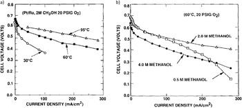
In 1994, a team from the Jet Propulsion Laboratory, the University of Southern California and Giner, Inc., sponsored by the Defense Advanced Research Projects Agency (DARPA), reported on the development of a liquid-fed DMFC. Reference Surampudi, Narayanan, Vamos, Frank, Halpert, LaConti, Kosek, Prakash and Olah115 This work showed improved performance when a solid electrolyte was used instead of an aqueous sulfuric acid electrolyte, demonstrating ∼300 mA cm−2 at 0.5 V and 90 °C (see Fig. 8). The authors discussed the effects of temperature and methanol concentration on performance, indicating that (i) higher temperatures led to increased output, (ii) optimum methanol concentrations lay between 0.5 and 2M, and (iii) methanol crossover limited the performance, particularly at methanol concentrations above 2M. In 1995, a team from the University of Newcastle reported a vapor-fed DMFC yielding 75 mA cm−2 at 550 mV and ∼100 °C, when operating with 1 vol% methanol. Reference Shukla, Christensen, Hamnett and Hogarth30 The authors reported steady performance over 8 h without apparent degradation. In 1996, a group from Los Alamos National Laboratory demonstrated current densities as high as 370 and 670 mA cm−2 (at 110 and 130 °C, respectively) at 0.5 V by optimizing the MEA using the DTM. Reference Ren, Wilson and Gottesfeld28 Meanwhile, by varying temperature (in the range of 60–120 °C), methanol concentration (0.1M, 0.5M, 2.5M, and 4.0M), and the Nafion membrane thickness (comparing 117, 115, and 112), scientists from Korea Institute of Energy Research identified a window of optimal DMFC operating conditions that yielded 230 mA cm−2 at 0.55 V. Reference Hwan Jung, Hyeong Lee, Soo Kim and Ryul Shin116 In addition, authors also reported that performance could be decreased by changes in the catalyst particle size, crystallinity, and composition induced by heat-treatment of the catalyst.
Effect of (a) temperature and (b) fuel concentration on cell performance. Reproduced with permission from Elsevier, Copyright 1994. Reference Surampudi, Narayanan, Vamos, Frank, Halpert, LaConti, Kosek, Prakash and Olah115

The method of MEA preparation has been shown to have a significant impact on DMFC performance. DMFCs fabricated using CCM have generally shown better performance than those fabricated using DTM, mainly due to increase in the thickness and porosity of the cathode. In contrast, the thickness of the anode does not appear to have a significant impact. Reference You, Lee, Cho, Kim, Pak, Lee, Park and Park111 One study highlighted a 39% performance improvement from the CCM-based MEA fabrication, attributing the enhancement to the favorable porosity. Reference Liu, Wang, Wang, Ye, Wang, Tian and Wang117 To improve anode performance, it has recently been demonstrated that anodic treatment of anode catalyst at 0.8 V versus DHE prior to DMFC operation results in a significant improvement in DMFC performance, despite also triggering some ruthenium dissolution and a decrease in electrochemical surface area. Based on data supporting reorganization of the Nafion on the catalyst surface, this improvement was attributed to the formation of an improved interface between catalyst and Nafion ionomer. Reference Joghee, Pylypenko, Wood, Corpuz, Bender, Dinh and O'Hayre118
Long-term degradation is one of the major challenges impeding DMFC commercialization. Among notable studies examining DMFC degradation, a 30% loss of original power density was reported for a DMFC operated at a low current density of 100 mA cm−2 for 75 h. The performance loss was primarily attributed to delamination of the catalyst layer and agglomeration of the catalyst, which was especially severe at the anode. Reference Liu, Zhou, Zhao, Xin, Sun and Yi119 Not surprisingly, longer durability tests have also confirmed degradation due to catalyst agglomeration and the consequent loss of electrochemically active surface area. Reference Guo, Sun, Wu, Sun, Yan, Cao, Yan, Su and Xin120,Reference Wang, Rivera, Wang, Zhang, Feng, Lewis and Smotkin121 In a study examining 500 h of operation, performance losses of 34% were recorded and attributed to delamination at the interface, particle agglomeration and ruthenium leaching and crossover. Reference Prabhuram, Krishnan, Choi, Lim, Ha and Kim122 In another study, a gradual decrease in the performance of a DMFC monitored for a period of 600 h was primarily assigned to degradation of the cathode. Reference Park, Scibioh, Kim, Kim, Oh, Lee and Ha123 At higher temperatures, the rate of degradation is higher due to the formation of pinholes in the membrane in concert with delamination and degradation of cathode. Reference Park, Kim, Seo, Yu, Cho and Bae124 Also, at higher temperatures, ruthenium dissolution/leaching from PtRu/C is accelerated when the anode experiences potential greater than 0.363 V versus DHE. Reference Guo, Sun, Wu, Sun, Yan, Cao, Yan, Su and Xin120 The DMFC performance and durability data are summarized in Table 4.
Electrochemical impedance and physiochemical analysis of MEAs after 1000 h of continuous operation show additional degradation mechanisms beyond catalyst activity losses. One notable degradation mechanism is an increase in cathode mass transport resistance associated with changes in its morphology and decreased hydrophobicity. Reference Kim, Shin, Park, Song and Kim132 Membrane degradation can also contribute to long-term performance losses in DMFCs. A DMFC made with poly(tetrafluoroethylene-co-perfluoropropyl vinyl ether)-graft-poly(styrene sulfonic acid (PFA-g-PSSA) membrane demonstrated 26.8% loss in voltage after testing for 2066 h, with losses attributed to catalyst agglomeration and reduced conductivity of the membrane. Reference Kang, Jung, Shin, Lim, Kim, Shul and Peck129 Performance loss due to interfacial delamination between the electrode and membrane was shown to be greater for wholly aromatic sulfonated poly(sulfone) membranes when compared to Nafion membranes. Reference Kim and Pivovar133 While methanol crossover can be reduced by using alternative membranes Reference Kang, Jung, Shin, Kim, Shul and Peck134 or by microporous layers with ultra-small (˂5 µm) pores, Reference Chin, Yan and Wang135 it is important to note that decreased methanol crossover does not necessarily translate into increased power. Reference Park, Seo, Kang, You, Cho and Na136
DMFC performance using anion exchange PEMs instead of the more common proton-based Nafion membrane has been evaluated by several groups, most of whom report higher ohmic resistance, but lower methanol crossover. Reference Yu and Scott94,Reference Scott, Yu, Vlachogiannopoulos, Shivare and Duteanu131 Matsuoka et al. report that the OCV of an AEM-DMFC is 100–200 mV higher than a comparable DMFC made with Nafion. Reference Matsuoka, Iriyama, Abe, Matsuoka and Ogumi130 Several other studies have demonstrated higher OCV and improved performance from AEM-DMFCs. Reference Kim, Momma and Osaka137,Reference Kim, Kim, Hwang and Lee138 Scott et al. demonstrated an AEM-DMFC with a power density of 16 mW cm−2, when operating at 60 °C with oxygen and 6 mW cm−2 when operating at ambient temperature with air. Reference Scott, Yu, Vlachogiannopoulos, Shivare and Duteanu131 An AEM-DMFC fabricated with a Tokuyama-006 membrane using CCS method showed peak power densities up to 168 mW cm−2. Reference Prakash, Krause, Viva, Natrayanan and Olah47 Another study achieved maximum power densities of 117 mW cm−2 in oxygen and 100 mW cm−2 in air, respectively, while using Tokuyama A-201 membrane and significantly lower catalyst loadings than those shown in previous reports. Reference Joghee, Pylypenko, Wood, Bender and O'Hayre48 This work also demonstrated that modifying a PtRu/C anode catalyst with nitrogen enables even higher power densities, 140 mW cm−2 in oxygen and 110 mW cm−2 in air. Ionomer content was shown to greatly affect the performance of an AEM-DMFC fabricated using the dry spraying method. Reference Bunazawa and Yamazaki139 While AEM-DMFCs offer higher OCV and perhaps slightly better initial performance than Nafion-based DMFCs, the robustness of alkaline membranes typically suffers compared to Nafion-type membranes, resulting in more rapid performance losses. Reference Prakash, Krause, Viva, Natrayanan and Olah47
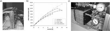
Moving from single-cell studies to stack development, in the late 1990s Siemens worked on the development of larger-sized DMFCs operating under air conditions, starting with 3–60 cm2 single cells, followed by a three-cell stack. The stack produced 1.4 V at 0.1 A cm−2 under air operation, yielding a total power output of 77 W. This was the highest total power output for an air-operated multicell DMFC stack reported at that time. Reference Dillon, Srinivasan, Arico and Antonucci11 In 2000, Los Alamos National Laboratory published on the development of DMFCs with new stack technology utilizing a 2 mm pitch per cell that was suitable for both portable power and transport applications. Among other findings, the loading and nature of the catalyst and catalyst layer structure and composition were found to be essential factors in the DMFC optimization. Reference Ren, Zelenay, Thomas, Davey and Gottesfeld140 Figure 9 shows a 3-cell short stack and its performance along with a photograph of a 500 W 71-cell DMFC stack developed at Forschungszentrum Jülich. These stacks also utilized a 2 mm cell pitch. Reference Dohle, Schmitz, Bewer, Mergel and Stolten125 Around the same time, Motorola Labs investigated ceramic and graphite-based DMFC stack designs. They eventually settled on a graphite-based stack that in comparison to a previous ceramic-based stack generated over 3 times higher peak power density (77 W L−1 versus 26.1 W L−1), mainly due to an increase in the active area per unit stack volume and a higher temperature inside the graphite stack under steady state operation. Reference Xie, Bostaph and Pavio126 Performance of the DMFC stack, which produced 54 W (85 mW cm−2) in air and 98 W (154 mW cm−2) in oxygen, was found to be highly sensitive to the distribution of the reactants. A 20% increase in power density was observed when implementing a counter-flow arrangement for the reactants. Reference Kim, Lee, Lim, Oh and Ha127
Stacks developed at Forschungszentrum Jülich. (a) Photograph of the 3-cell short stack, (b) performance of the 3-cell short stack, and (c) photograph of the 500 W 71-cell stack. Reproduced with permission from Elsevier, Copyright 2002. Reference Dohle, Schmitz, Bewer, Mergel and Stolten125

In studies examining long-term DMFC operation, it has been demonstrated that the life of the fuel cell can be extended by periodic air cut-off, a strategy that was successfully implemented to achieve DMFC operation for over 1200 h. Reference Xie, Bostaph and Pavio126,Reference Park, Peck, Kim, Lim, Jung, Jang and Lee128 Air interruption control was also used on a 42-cell 400 W stack fabricated with graphite bipolar plates, demonstrating that each cell could maintain stable performance for over 500 h. Reference Joh, Hwang, Cho, Ha, Kim, Moon and Ha141 Regulating the air on-off condition and using moderate air flow rates can mitigate long-term performance losses, particularly on the cathode side. Reference Chen and Cha142
Another important issue for DMFC stacks is cold-start operation and operation under freezing temperatures. Investigation of the cold start operation of a 10-cell DMFC stack showed that self-heating operation is limited to temperatures above −10 °C. Reference Park, Peck, Kim, Lim, Lee, Ji and Jung143 A self-sustained 15-cell DMFC stack with a surface area of 45 cm2 was reported to provide 40 W at ambient temperature. Reference Manokaran, Vijayakumar, Thomman, Sridhar, Pitchumani and Shukla144
The drive to commercialize DMFCs for portable applications has led to significant research in air breathing systems and to the development of configurations that do not require ancillary balance of plant components and systems that are tolerant to higher methanol concentrations. Compared to DMFCs with active air supply, passive (“air breathing”) DMFC cells often require higher catalyst loadings to ensure good performance. Reference Bae, Kho, Lim, Oh, Hong and Ha145 A study comparing the performance of a series of passive DMFCs made from Nafion membranes of different thicknesses showed very similar performance at high methanol concentration (4M). Reference Liu, Zhao, Liang and Chen146 Guo and Faghri discussed the performance of a series of passive DMFC progressing in size from a single cell with 1 cm2 active area to single cells with 4.5 and 9 cm2 active area, and finally to two four-cell stacks with 18 and 36 cm2 active area, respectively. Reference Guo and Faghri147 This work reported higher power densities for 2M and 3M methanol concentrations as compared to 5M solution, with the latter resulting in higher methanol crossover and increased temperature. Reference Guo and Faghri147 A prototype of a 2 W passive DMFC with 8 cells using a porous carbon plate (PCP) platform was developed to accommodate 100% methanol. Reference Tsujiguchi, Abdelkareem, Yoshitoshi, Nobuyoshi, Shimizu, Sato and Matsuda148 PCP technology was also used to study the performance of a 30 cm2 active DMFC, demonstrating 42 mW cm−2 at 45 °C. Reference Nakagawa, Tsujiguchi, Sakurai and Aoki149 A passive 8-cell twin stack with total surface area of 32 cm2 achieved 16.9 mW cm−2 when operating at ambient temperature with 4M methanol. This stack was equipped with a fuel-feed device that allowed for self-regulation of the feeding rate, based on the discharging current of the stack. Reference Zhu, Liang, Liu, Ma and Wang150 Li and Faghri compared two passive stacks, one using 1M methanol and the other using pure methanol, obtaining similar performance for both stacks, although the pure methanol stack provides a clear advantage in energy storage density. Reference Li and Faghri151
Status of DMFC technology for portable electronic devices
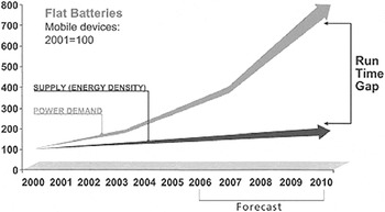
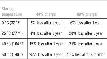
Over the years, Li-ion batteries have increasingly been used in the portable electronic industry to power laptop computers, mobile phones, digital cameras, and so on. In recent years, considerable progress has been made in manufacturing Li-ion batteries with increased energy density and lifetime. Reference Yomogita and Electronics152,Reference Anthony153 However, one can argue that these improvements have not kept up with the increasing power demands of portable electronic applications. Research by the Boston Consulting Group (BGP) in 2005 illustrates the fact that mobile device energy demand growth has exceeded the growth in battery energy capacity. This phenomenon is referred as the “run time gap” (Fig. 10) and while this study was published a decade ago, this issue continues to constrain the design features of current portable electronic devices. In addition to energy density limitations, Li-ion batteries face self-discharging and capacity fade issues that limit lifetime. For instance, Li-ion batteries can permanently lose 35% of energy capacity over the period of 12 months if exposed to 40 °C (Table 5). Reference Stone154
The runtime gap between device power demand and battery supply capability. [Source: Boston Consulting Group (BGP)]. Reproduced with permission from Elsevier, Copyright 2007. Reference Stone154

Permanent capacity loss for Li-ion batteries as a function of the storage conditions. (Reproduced with permission from Elsevier, Copyright 2007. Reference Stone154 )

Source: Battery University.com
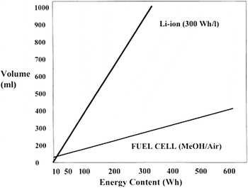
In this context, the higher energy density of methanol fuel provides an opportunity for DMFCs in the portable power sector. As discussed in the introduction, the theoretical specific energy density of methanol is significantly higher than the energy density of advanced Li-ion batteries, but a fair comparison of complete DMFC systems versus Li-ion batteries shows a much tighter race. Reference Hebling35,Reference Florez and Adolp36,Reference Gottesfeld155,Reference Dyer156 Nevertheless, as shown in Fig. 11, taking into account the additional system and packaging requirements associated with the DMFC, DMFCs offer an advantage compared to Li-ion batteries at higher energy contents and for larger system sizes.
Practical volumes of Li-ion battery and DMFC systems. Reproduced with permission from Elsevier, Copyright 2002. Reference Dyer156

Miniature DMFCs with methanol fuel cartridges instead of power cords and adapters allow consumers to enjoy a truly “wireless” experience, which is particularly useful in places where the power grid is unavailable. For example, DMFC-powered laptops are projected to enable up to one month of use between refueling (assuming eight hours of usage per day for five days a week). 157 The nascent portable DMFC market was estimated at approximately $17.5 million in 2010. 158 Forecasts project that the DMFC market could increase to $1.1 billion by 2016 and this will account for 85% of the portable fuel cell market by the end of the forecast period. Reference Eustis159 As discussed in more detail later, regulatory actions could promote increased use of DMFCs. The 2007 authorization of DMFC devices and cartridges on aircraft by the International Civil Aviation Organization and the US Department of Transportation is an important step in this regard. Reference Eustis159
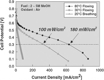
A number of companies and organizations are actively engaged in the development of prototype “miniature” and hybrid DMFCs for portable electronic applications. Reference Jung, Jo, Jung, Cho, Kim and Shin23,Reference Bostaph, Korpella, Fisher, Zindel and Hallmark160–Reference Witham, Chun, Valdez and Narayanan164 Early DMFC prototypes suffered from nonoptimized cell design, high electrocatalyst loading in both the anode and the cathode, deployment of unsuitable current collectors, and improper water management that resulted in poor air diffusion in the cathode. Recognizing that these issues required further solution, several significant advances were made by industry over the last 15 years. In 2002, Samsung Advanced Institute of Technology (SAIT, South Korea) developed a small monopolar DMFC (single cells are placed together in such a way that two positive poles or two negative poles are opposite to each other in pairs) using a new type of membrane and catalyst supported on mesoporous Reference Dohle, Mergel, Scharmann and Schmitz162 carbon that greatly reduced catalyst loadings. The advanced monopolar DMFC yielded excellent power densities even at ambient temperature as shown in Fig. 12, which enabled a notebook computer to run for 10 h on a 100 cm3 cartridge of methanol. Reference Chang24
Current/voltage plot for the DMFC cells developed by the Samsung Advanced Technology Institute (SAIT) in Korea. Reproduced with permission from Elsevier, Copyright 2002. Reference Hebling35

In 2006, SAIT developed a docking station, which was equipped with a DMFC. The DMFC offered a maximum power output of 20 W and could generate small amounts of power over long periods of time at low temperatures. 165 Subsequently, in 2009, SAIT developed a prototype DMFC for military applications which weighed 7.7 lbs and was capable of delivering a total of 1800 Wh of energy. 166 Although the company stated that field-test of the DMFC for military use would be conducted in 2010, further information on this product is not presently available.
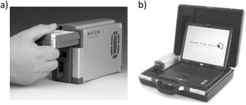
In 2003, the Smart Fuel Cell AG Company (Germany) successfully launched its first commercial DMFC (Smart Fuel Cell C25) for notebook computers. 167 This compact DMFC system, weighing just 1.1 kg, offered a continuous power output of 25 W at 12 V. Methanol feed in this cell was provided by a Smart Fuel Cell M125 cartridge the size of cigarette packet weighing just 150 g. The cartridge holds 125 cm3 of methanol, providing an average power output of 20 W with atleast 7 h runtime (see Fig. 13). The fuel cartridge in the Smart Fuel Cell from SFC uses 100% methanol. A water management system controls the optimal methanol concentration supplied to the fuel cell. In addition, SFC developed an automated cartridge filling and assembly line for its own methanol fuel cartridges and also established an international network of distributors.
(a) The miniature DMFC (Smart Fuel Cell C25) compact power system and (b) laptop computer integrated with miniature DMFC. Reproduced with permission from Elsevier, Copyright 2003. 167

A couple years later, a portable DMFC hybrid system fitted with an exchangeable 1.5 Ah lithium polymer rechargeable battery (SFC C20-MP) with a power output of 20 W was developed by Smart Fuel Cell AG. Reference Cristiani and Sifer168 This system weighed 2 kg and was fueled by hot-swappable, 500 mL methanol fuel cartridges. Two SFC C20-MP systems were developed: one was designed for moderate ambient temperature operation (1–35 °C) and operated with neat methanol fuel (normal unit). The other system was designed for high ambient temperature operation (1–50 °C) and operated on a methanol–water mixture (desert unit). The US Army Communications-Electronics Research Development and Engineering Center (CERDEC) tested these two systems and found that the normal unit had a peak fuel efficiency of 19.1% at 19.6 W average power output, whereas the desert unit had a peak fuel efficiency of 19.7% at 20 W average power output. Reference Cristiani and Sifer168 Both systems showed improved reliability and electrical characteristics when compared with previous DMFC systems tested by CERDEC. However, it was concluded that further work was needed to continue to improve these systems. Reference Cristiani and Sifer168
In 2008, SFC AG developed a DMFC (carrying a 10 L cartridge weighing 18.5 lbs) which was claimed to provide the same energy content as 595 lbs of batteries for use in remote video surveillance applications for round-the-clock, unmanned, off-grid power in any location. 169 This DMFC operated a surveillance camera for up to 8 weeks without any intervention. SFC AG manufactured and shipped 13,000 DMFC products with 100,000 fuel cartridges for consumer electronics from the year 2002 to 2009. More recent sales information is not presently available. Reference Boehm170
In 2005, Neah Power Systems commercialized small DMFCs using silicon-based membranes in place of the standard polymer-based electrolyte, thus eliminating the issues associated with polymeric membranes typically used in the conventional DMFC systems. 171 The company advertised the design as offering high catalytic surface area while simultaneously maintaining a small form-factor, which is important for producing higher power density. In 2009, Neah Power Systems developed a portable DMFC equipped with silicon-based architecture (porous silicon, catalyst-supporting electrode structure) and circulating liquid electrolyte capable of generating a power density greater than 180 mW cm−2. Reference Cross, Reiman and D’Couto172 Current status on this high power density portable DMFC is not available.
In 2008, Mechanical Technology Inc., (MTI) developed its third generation “Mobion Technology”, aimed to overcome many of the technical barriers preventing commercialization of DMFCs for handheld and portable electronic devices. The Mobion Technology provided a simplified architecture that eliminated the need for gravity and remix pumps and condensers, while allowing utilization of the high energy density of a 100% methanol feedstream, supplied in hot-swappable cartridges. In 2008, the company unveiled a Mobion external power pack prototype with a removable methanol cartridge (Fig. 14) that could provide 25 Wh of power or up to 25 h of power from each methanol cartridge. Reference McConnell173 Unfortunately, at the end of 2011, MTI had shelved the “Mobion Technology” because the micro fuel cell division had incurred $60 million in losses without producing any commercial products. 174 However, as per 2013 report, MTI was exploring new opportunities to develop the DMFC technology again. 174
The Mobion DMFC charger from MTI Micro based on Mobion chip platform (inset) eliminates the need for cumbersome water management around the micro fuel cell. Reproduced with permission from Elsevier, Copyright 2009. Reference McConnell173

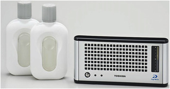
In 2004, Toshiba Inc. (Japan) developed a highly compact DMFC, which was claimed to be the smallest DMFC at that time. 175 Total weight was 130 g with a volume of 140 cm3 including the fuel cell cartridge. The system could generate 1 W of continuous power for approximately 20 h on 25 cm3 of methanol. The Toshiba system used the water produced in the cathode to dilute the methanol supplied to the anode, thereby eliminating the need of predilution and reducing the size of the fuel reservoir. In 2005, Toshiba unveiled two DMFC prototypes, one generating 100 mW and the other generating 300 mW that were integrated into MP3 players with fuel capacities of 3.5 and 10 mL, respectively. 176 In 2009, Toshiba launched its first commercial DMFC product called “Dynario™” (Fig. 15). Reference Li and Faghri177 The Dynario™ (with dimensions of 150 × 21 × 74.5 mm3 and a weight of 280 g) was intended to deliver on-the-go power to digital consumer products. The Dynario™ utilized a high concentration methanol solution and produced 2.5 W, which was sufficient to charge a typical cell phone battery twice. 175 On a trial basis, Toshiba manufactured 3000 Dynario™ units in 2009 and shipped this product to customers to gauge their reaction. The cost of this product was $327, which included five 50 mL methanol cartridges and additional methanol cartridges cost $35 each. 178
The DMFC external power supply Dynario™ launched by Toshiba. Reproduced with permission from Elsevier, Copyright 2013. Reference Li and Faghri177

In 2009, Sony launched a cordless mobile phone charging system powered by a hybrid DMFC/Li-ion battery system. Reference Kariastsumari179 The cordless speaker system was driven by four DMFC single cells sharing a 270 mL methanol tank, with each DMFC single cell providing a power of 550–600 mW. The system was supplemented with a Li-ion secondary battery to provide higher power outputs when required. The hybrid system could provide a maximum power output of about 10 W. Assuming 3 h/week use of the cordless speaker system in a home entertainment environment, the speaker can be powered for a year without refilling the tank. Although miniature DMFCs have shown progress toward commercialization, further improvements in energy, power density, and miniaturization of the total package are required. Other aspects requiring attention include, increasing stack longevity, optimization of heat/water management, build-out of the fuel cartridges/canister distribution infrastructure, and establishment of new regulations.
Status of DMFC technology for transportation
Methanol ICEs
Methanol is a simple chemical with excellent combustion properties that makes it an ideal fuel for ICE-driven vehicles. 180 Methanol contains about half the energy density of gasoline. Despite its lower energy content, methanol has a higher octane rating than gasoline (∼100), which facilitates greater fuel/air compression ratios (10–11 to 1 versus 8–9 to 1 for gasoline engine) and thus higher efficiencies. Reference Olah, Goeppert and Prakash15 In addition, methanol is a safer and more environmentally benign fuel. In fact, methanol vehicles produce lower pollutant emissions, including decreased hydrocarbon emissions as well as decreased levels of NO x , SO2, and particulates when compared to gasoline-powered vehicles.
In the late 1980s, automotive companies including General Motors, Ford, Chrysler, Volvo, and Mercedes developed the technology to transform existing engine models into methanol flexible fuel vehicles (FFVs) for the cost of a few hundred dollars per vehicle. Reference Olah, Goeppert and Prakash15 This methanol FFV option is available on a number of car/truck models and allows a vehicle to run on any combination of methanol and gasoline up to M-85, a blend of 85% methanol and 15% unleaded gasoline. In 1997, the number of U.S. methanol FFVs reached 21,000 units. Approximately 15,000 of these vehicles were located in California, where over 100 methanol refueling stations were located. 181 Unfortunately, in the late 1990s, the attractiveness of methanol as a transportation fuel was diminished by the lower price point of gasoline (less than $1.00 per gallon at that time). 182 Since then, gasoline prices have soared, but the methanol FFV has not yet rebounded. In the year 2009, the U.S. Congress passed the Open Fuel Standard Act, mandating that 50% of the vehicles produced in the US market must be compatible with blends up to M-85 and E-85 fuel (a blend of 85% of ethanol and 15% gasoline) by 2012 and that 80% of the vehicles produced should have the fuel option by the year 2015. 166 Recently, the Lotus car company unveiled a “tri-flex-fuel” vehicle, the Exige-270E, which can run on a mixture of gasoline and methanol as well as gasoline and ethanol. 183
The chemical and physical properties of methanol raise some issues for use in ICEs. Methanol can corrode some of the metals used in modern automotive engines, including aluminum, zinc, and magnesium. 184 It can also react with plastics, rubbers, and gaskets, causing them to soften and swell and resulting in eventual leaks or system malfunctions. Therefore, automotive systems should be specifically designed for pure and blended methanol. Cold-start represents another major issue using pure methanol. Cold-start problems can occur because methanol lacks the highly volatile compounds such as butane, isobutene, or propane generally found in gasoline, which help to provide ignitable vapors to gasoline engines even under the most frigid conditions. Reference Cheng and Kung185
To further increase efficiency and lower emissions, methanol fed fuel cell vehicles (FCVs), which are fully qualified as zero emission vehicles (ZEVs) 186 are being examined as an alternative for automotive power. The application and status of methanol-based fuel cell technology for the transportation sector are further discussed below.
DMFC technology to replace automotive ICEs
Both hydrogen and methanol fed FCVs can potentially offer higher efficiency and lower emission levels than either gasoline or pure methanol/blended methanol-powered ICE vehicles. Reference McNicol, Rand and Williams12,Reference Olah, Goeppert and Prakash15,Reference Armstrong187 Presently, automotive companies are investing most heavily in hydrogen fed PEMFCs for FCVs. PEMFCs have high power density and a low working temperature (about 70 °C) that allows for rapid start-up. The electric efficiency is usually 40–60% and the output power can be changed quickly to meet a variable load. As a result of these characteristics, PEMFCs are considered to be promising for transport applications and a large number of companies are actively engaged in their development. Reference Schaller and Gruber188–Reference Folkesson, Andersson, Alvfors, Alaküla and Overgaard191 Despite these advantages, both on-board and stationary hydrogen storage and distribution present significant challenges. Reference Ogden, Steinbugler and Kreutz9,Reference Armaroli and Balzani10 The primary aim of any on-board fuel storage system is to provide a safe system to deliver sufficient fuel to satisfy the driving range requirement of the vehicle. These conditions must be accomplished at low cost without adding excessive weight and compromising the interior volume. At standard temperature and pressure (i.e., in the absence of compression), hydrogen gas requires about 3000 times more space than gasoline for an equivalent amount of energy. Reference Armaroli and Balzani10 Storing under pressure improves the energy density by volume, allowing the tank to be smaller but not lighter. Currently, compressed hydrogen is the preferred solution in most fuel cell powered prototype vehicles, but its usage is far from satisfactory. Currently, hydrogen is pressurized from ∼350 to 700 atm in tanks made of new composite light-weight materials, such as carbon fiber with aluminum/steel/polymer liners, but these materials are very expensive. Reference Armaroli and Balzani10 Even at 700 atm, hydrogen has 4.6 times lower volumetric energy content than gasoline, and the gravimetric energy density comparison is even less favorable (due to the considerable weight of the tanks). Moreover, in contrast to gasoline tanks, a hydrogen tank cannot adopt a shape that best suits the vehicle because the compressed hydrogen tank must be cylindrical to ensure its integrity under high pressure. Hydrogen tanks can therefore pose spatial integration issues. An intensive research is underway in an effort to find a more safe/convenient way to store hydrogen in fuel cell powered vehicles. Reference Davis, Edelstein, Evenson, Breacher and Cox192–Reference Lipman194
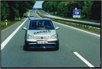
In view of the challenges associated with on-board hydrogen storage for PEMFC-powered vehicles, some companies have shown interest in developing DMFC-based FCVs. Reference Dillon, Srinivasan, Arico and Antonucci11,Reference Harris195–Reference Baldauf and Preidel202 As discussed previously, methanol can significantly mitigate on-board storage constraints. Moreover, it can be distributed using the existing gasoline distribution infrastructure with only minor modifications. Reference Dillon, Srinivasan, Arico and Antonucci11,Reference McNicol, Rand and Williams12 In 1998, General Motors Corporation (GMC) with its German subsidiary, Opel, introduced a methanol fuel-cell powered car called “Zafira”. 186 The car was four-seat equipped with 50 kW electric motor. However, in 2000, Opel unveiled an updated version of Zafira, which run on hydrogen. 183 In the same year, Daimler-Chrysler (Germany) unveiled NECAR 5 powered by a PEMFC, where the hydrogen was produced by on-board methanol reformation. The NECAR 5 was the first vehicle in which an entire fuel cell system with a built-in methanol reformer was accommodated within the underbody of a compact car platform (see Fig. 16). The car could carry five passengers with their luggage and attained a top speed of 90 mph. 186
Mercedes-Benz A-class compact car powered by a methanol-fueled FC system (although notably not a DMFC). Reproduced with permission from Mercedes-Benz – Copyright: Daimler AG.

In the following year, Ballard Power Systems Inc. (BPSI, Canada) in collaboration with Daimler-Chrysler, developed a 6 kW DMFC system for a one-person vehicle. Reference Dillon, Srinivasan, Arico and Antonucci11,186 In this system, both the anode and cathode catalysts were impregnated over an oxidized carbon substrate (to increase the wettability of the carbon substrate). The MEAs were fabricated by a conventional approach by hot pressing the anode and cathode layers to either side of a solid polymer electrolyte. Reference Zhang, Colbow and Wilkinson196 The details of the stack assembly, design, and performance of this system were not revealed. In 2003, Yamaha (Japan) developed the FC06 prototype DMFC-powered motorcycle with an output power of 500 W. 203 In 2007, an improved version of the DMFC-powered two-wheeler (FC-Dii) was introduced with an output power of 1 kW. The cell stack provided a 30% system electrical efficiency in a light-weight, compact, and high power density package. 204
Among hybrid electric vehicles (HEVs), the plug-in HEV has already made an impact in the market. On-board batteries provide the primary power, enabling typical driving range of 30–60 km before lengthy (8+ hour) recharging is required. Reference Chan7 Some companies have therefore examined hybrid DFMC/battery systems to extend range and improve HEV performance. Reference Chan7,186 Toyota (Japan) developed a 25 kW DMFC system that works in conjunction with a downsized battery pack to power its RAV 4 SUV. In this hybrid system, batteries are constantly recharged by the DMFC. Toyota's design draws extra power from the batteries to supplement the fuel cell during acceleration. The batteries also enhance the vehicle by providing instant power, and facilitate the initial warm-up cycle required to bring the fuel cell up to power upon cold start. 186 In the year 1999, Georgetown unveiled a hybrid DMFC-battery system to power a prototype 40-foot transit bus using a 100 kW methanol-fueled phosphoric acid fuel cell. In this system, the fuel cell provided the baseload motive power while the batteries provided surge power and enabled storage of energy provided by regenerative braking. The speed and range of this hybrid bus was comparable to that of standard diesel buses, and it could be refueled quite easily and quickly. Even compared to clean-burning natural gas powered buses, fuel cell/hybrid buses are expected to have less than one-tenth of the hydrocarbon emissions and only 2% of the CO emissions as well as virtually no emission of nitrogen oxides or particulate matter (PM). 186
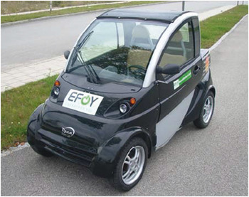
Julich Forschungszeatrum (Germany) developed a commercial electric vehicle (EV) powered by a hybridized DMFC system (comprised of 100 single cells with a power output of 1.3 kW) coupled to a bank of Li-ion batteries. 205 Under normal operation, the DMFC drives the electric motor, while the battery boosts the power during start-up or uphill acceleration. Interestingly, in this DMFC system, the Pt loading level was reduced by 50% compared to other state-of-the-art DMFC electrodes. Furthermore, to ensure a lighter stack, many of the metallic stack materials were replaced with graphite components. A collaboration aimed at scooters as a potential early-adopter market entry point for DMFC technology was formed by Neah Power and EKO (India) to develop a DMFC to charge battery-powered “EV 60” electric scooters. 206 This second-generation electric scooter is marketed in the USA, Europe, and Asia. Smart Fuel Cell AG developed the EFOY DMFC + Li-ion hybrid system for light-weight EVs weighing less than 500 kg as shown in Fig. 17. Reference Steckmann207 The DMFC is equipped with an automatic control system that constantly monitors the battery's charge state. Whenever it drops below a predefined level, the DMFC automatically begins charging the battery. Once the battery is fully charged, the fuel cell automatically returns to standby. This eliminates unfavorable operation modes like partial load operation and increases the total efficiency ratio. The company has successfully proved its reliability and functionality in many off-grid and light electric vehicle applications. The EVOY fuel cartridges are available at almost 1000 sales points in Europe and the US.
SFC developed EFOY DMFC powered Li-ion hybrid system for small electrical cars weighing less than 500 kg. Reproduced with permission from World Electric Vehicle Journal, Copyright 2009. Reference Steckmann207

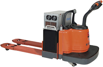
In 2008, Oorja Protonics developed the first DMFC on-board charging system, the OorjaPack™, which was designed to power material handling vehicles like forklifts (Fig. 18). Reference Malhotra208 The DMFC system helps to continuously replenish the energy depleted by the operation of the vehicle and maintains the battery state of charge during operation between 50 and 80%. Using the hybrid DMFC/battery system eliminates the need for extra batteries and eliminates the downtime associated with periodic battery charging or swap-out. The resulting savings of 30–45 min per day per vehicle results in increased operational efficiency as well as productivity savings.
DMFC (Oorja Protonics™) for on-board battery charging for material handing vehicles. Reproduced with permission from Elsevier, Copyright 2012. Reference Malhotra208

As discussed above, while progress continues on the development of DMFC systems for small vehicles or scooters, most current efforts for large-scale passenger cars and trucks have focused on hydrogen fed PEMFCs.
Key challenges in DMFC technology
Of all the potential applications for DMFC, the portable electronics power market appears to be the most compelling in the short-to-intermediate term. While several portable devices equipped with DMFC can already be purchased in niche commercial markets, widespread commercialization into mass markets such as mobile phone and laptops still faces numerous technical challenges. One of the key challenges for DMFC is increasing the power density and reducing the size of the system. In the transportation sector, although using DMFC technology alleviates the on-board fuel storage issue, the cost, power density, and efficiency of the DMFC system are far from satisfactory when compared against H2-based fuel cells. Perhaps the greatest of many critical challenges impeding DMFC commercialization at larger scales is system costs, which are driven by materials and manufacturing challenges.
Materials challenges
Sluggish MOR
The MOR on state-of-the-art anode catalysts (such as PtRu supported on carbon or PtRu black) is significantly hindered because of the poor electrokinetics. The rate of MOR in the anode of a DMFC is quite slow as compared to that of the hydrogen oxidation reaction in the anode of the PEMFC. The poor electrokinetics of the MOR leads to a high activation overpotential, which in turn, lowers the power density and the efficiency of the cell. To improve the kinetics of the MOR, higher catalyst loadings are used (>2 mg cm−2). Reference Dohle, Schmitz, Bewer, Mergel and Stolten125 This obviously increases the cost of the system. Even if the catalyst loading is increased enough to ensure good initial performance, the long-term stability of the PtRu/C catalyst suffers, particularly in acid-based systems, because of the ruthenium dissolution processes. Reference Gotz and Wendt42,Reference Zhou, Zhou, Li, Zhou, Song, Sun, Xin, Douvartzides, Goula and Tsiakaras45,Reference Ralph and Hogarth46,Reference Lizcano-Valbuena, Bortholin, Neto, Paganin and Gonzalez49,Reference Piela, Eickes, Brosha, Garzon and Zelenay85 The gradual dissolution of ruthenium from the anode and its migration to cathode during the operation of DMFC further decreases the kinetics of both the MOR and ORR in the anode and cathode, respectively. Reference Piela, Eickes, Brosha, Garzon and Zelenay85,Reference Gancs, Hult, Hakim and Mukerjee209
To improve performance and stability of the PtRu catalyst, work has been focused on developing PtRuX-based ternary catalysts, where X is Mo, Sn, Os, or W. Reference Gotz and Wendt42,Reference Zhou, Zhou, Li, Zhou, Song, Sun, Xin, Douvartzides, Goula and Tsiakaras45,Reference Lizcano-Valbuena, Bortholin, Neto, Paganin and Gonzalez49,Reference Lima, Coutanceau, Leger and Lamy210 Among these ternary catalysts, PtRuMo is reported to be more active for the MOR than bimetallic PtRu. Reference Lima, Coutanceau, Leger and Lamy210 However, the stability of PtRuMo is not known. As discussed in the preceding sections, chemical modification of the support is also being explored as a way to improve catalyst performance and durability. Reference Zhou, Neyerlin, Olson, Pylypenko, Bult, Dinh, Gennett, Shao and O'Hayre56–Reference Olson, Dameron, Wood, Pylpenko, Hurst, Christensen, Bult, Ginley, O’Hayre, Dinh and Gennett60 Of particular note, PtRu catalysts supported on nitrogen modified carbon supports have been shown to exhibit significantly higher performance and stability when compared to undoped counterparts. Reference Corpuz, Olson, Joghee, Pylypenko, Dameron, Dinh, O'Neill, Hurst, Bender, Gennett, Pivovar, Richards and O'Hayre61–Reference Corpuz, Wood, Pylypenko, Demeron, Joghee, Olson, Bender, Dinh, Gennett and Richards63 Using nitrogen modified carbon as the supporting material for PtRu in the anode of the DMFC could be helpful in achieving higher power density while simultaneously decreasing the amount of catalyst required.
Methanol crossover
DMFCs experience significantly lower OCVs (∼0.7 to 0.8 V versus ∼1.2 V theoretical) and lower power density than H2-PEMFCs. The lower OCV and performance in the lower current density region is mainly attributed to two factors, methanol crossover from the anode to cathode through the Nafion membrane and the poor kinetics of the MOR as discussed above. Reference Qi and Kaufman211,Reference Wang, Wasmus and Savinell212 Methanol crossover creates a mixed potential in the cathode, and also reduces the methanol utilization in the anode, thereby reducing the voltage of the DMFC by as much as 400 mV. Reference Scott, Taama, Argyropoulos and Sundmacher213 Methanol crossover occurs mainly due to the structure of the Nafion membrane. The Nafion consists of hydrophobic main chains and hydrophilic side chains containing ionic sulfonic acid (–SO3H) groups, where the latter groups cluster together to form ionic channels. While the flow of water through ionic channels helps to carry the protons and thus permits high proton conductivity (desirable), it also permits the flow of methanol across the membrane from the anode to cathode. The formation of wider ionic channels facilitated by the aliphatic polymer structure of Nafion leads to high methanol permeability. Because of this limitation, researchers have modified the Nafion type membranes and also developed new types of polymeric membranes to meet the additional membrane criteria needed for high-performance DMFC applications. These criteria include reduction of methanol crossover, maintenance of optimum proton conductivity, and an increase in the chemical stability. Reference Antonucci, Arico, Creti, Ramunni and Antonucci86–Reference Wang, Wainright, Savinell and Litt91,Reference Li, Zhang and Wang93
Important progress has been made in addressing these basic needs. For example, researchers from the Loss Alamos National Laboratory developed a new set of membranes from the poly(arylene ether sulfone) family (branded as 6F and 6F-CN), which showed higher initial DMFC performance than Nafion (Fig. 19), Reference Zelenay, Brosha, Davey, Eickes, Fields, Garzon, Neergat, Pivovar, Purdy, Ramsey, Rowley, Wilson and Zhu214 possibly due to reduced methanol crossover. Furthermore, such membranes showed only slight performance degradation even after 700 h of durability testing. Recently, blended membranes consisting of an acid polymer and a basic polymer with similar aromatic backbones have emerged as a promising technology to reduce methanol crossover and achieve higher DMFC power density compared to Nafion. Reference Fu, Manthiram and Guiver215–Reference Lee, Li, Manthiram and Guiver218 The blended membrane approach involves the tethering of an N-heterocycle group to an aromatic polymer like poly(sulfone) (PSf) or poly(ether ether ketone) (PEEK) to obtain a polymer with basic (rather than acidic) character. This polymer is then blended with an aromatic acid polymer such as sulfonated poly(ether ether ketone) (SPEEK) or sulfonated poly(sulfone) SPf. As an example, a 60 µm thick blended SPEEK/poly(sulfone)-amino benzimidazole (PSf-ABlm) membrane has been shown to exhibit significantly lower methanol crossover than Nafion 115 (thickness 125 µm). Reference Manthiram219 However, the proton conductivity of the blended membrane is lower than that of the Nafion membrane. Although the proton conductivities of blended membranes tend to be lower, the lower thickness of these membranes enables lower total ionic resistance, resulting in lower voltage loss and higher power density than cells based on Nafion 115 or Nafion 117 membranes. Because of the lower methanol crossover, blended membranes exhibit higher OCV and allow the operation of DMFC with higher methanol concentrations, thereby enhancing DMFC power density. Reference Lee, Li, Manthiram and Guiver218 In addition, blended membranes exhibit excellent chemical, thermal, and mechanical stabilities and are much less expensive than Nafion-based membranes.
DMFC performance obtained with four different membranes (Nafion 117, 6F-40, 6F-CN-35, and BPSH-35) at an ambient air pressure and at the temperature of 80 °C. Reproduced with permission from Los Alamos National laboratory – FY progress report, 2003. Reference Zelenay, Brosha, Davey, Eickes, Fields, Garzon, Neergat, Pivovar, Purdy, Ramsey, Rowley, Wilson and Zhu214

As an alternative to blended membranes, alkaline membranes also show lower methanol crossover and can offer improved electrochemical kinetics. Commercially available AEMs include MORGANE-ADP and an ammonia-based AEM membrane from Tokuyama Co. Japan. Recent literature reports show that DMFCs made with Tokuyama alkaline membrane (fed along with NaOH/KOH solution) exhibited higher OCV and comparable or slightly higher performance than acid-based DMFCs. Reference Prakash, Krause, Viva, Natrayanan and Olah47,Reference Joghee, Pylypenko, Wood, Bender and O'Hayre48 The ionic mobility of OH− is relatively low compared to that of H+; thus it is generally required to feed an alkaline liquid (KOH/NaOH solution) along with methanol to improve its OH− ionic mobility during the DMFC operation. However, reaction of the OH− ions with the CO2 produced during the cell operation can result in the formation of carbonate and bicarbonate ions. Reference McLean, Niet, Prince-Richard and Djilali220,Reference Cifrain and Kordesch221 Formation of these ions pose a detrimental effect to the performance of a cell by means of (i) blocking the active sites of the electrodes through the formation of metal carbonate crystals (most commonly as Na2CO3 or K2CO3), Reference Cifrain and Kordesch221 (ii) depletion of the OH− ions concentration at the anode, thereby decreasing the MOR kinetics, Reference Kim, Kim, Hwang and Lee138 and (iii) incorporation of carbonate/bicarbonate ions into the membrane, thereby decreasing conductivity and creating an unfavorable pH gradient across the membrane. Reference Wang, Li, Hu, Zhuang, Lu and Xu222 The development of AEMs with higher ionic conductivity and good chemical stability may open up promising avenues for lower-cost, higher-performance DMFCs.
Ruthenium dissolution from PtRu catalyst in the anode
During DMFC operation, ruthenium dissolution takes place from the PtRu catalyst in the anode; it can subsequently migrate through the CEM and redeposit in the cathode, which decreases the activity of both anode and cathode and in turn affects cell performance and durability. Reference Piela, Eickes, Brosha, Garzon and Zelenay85,Reference Prabhuram, Krishnan, Choi, Lim, Ha and Kim122 Ruthenium dissolution occurs during the normal DMFC operation, where the anode experiences potentials around 0.3–0.5 V versus DHE, even though the thermodynamic reversible potential for ruthenium oxidation is significantly higher (E°Ru/Ru(OH)3 = 0.74 V and E°Ru(OH)3/RuO2.H2O = 0.94 V versus reversible hydrogen electrode). Reference Pourbaix223 Although ruthenium has a relatively high thermodynamic reversible oxidation potential, the observed ruthenium dissolution in the lower potential region (0.3–0.5 V versus DHE) of the anode is often attributed to the low Ru(OH)3 activity in the catalyst layer and the relatively high operating temperature of the cell. Reference Piela, Eickes, Brosha, Garzon and Zelenay85 Occasionally, DMFC anodes can experience potentials greater than 0.7 V versus DHE, for example during deep discharging or under short circuit. Such situations trigger even greater ruthenium dissolution. Reference Chen, Sun, Liang, Mao, Li, Wang, Xin, Chang, Pak and Seung224 Piela et al. reported ruthenium leaching from the anode and migration to the cathode even when the DMFC stack was operated under prehumidified conditions. Reference Piela, Eickes, Brosha, Garzon and Zelenay85 Under this prehumidified condition, part of the ruthenium species (mostly likely RuO2) in the PtRu anode might be relatively loosely bound and easily susceptible to dissolution and migration. Typical PtRu catalysts are not perfectly homogeneous; ruthenium normally exists in various forms including nonalloyed ruthenium metal, ruthenium oxides (RuO2), and ruthenium oxyhydroxide (RuO x H y ) in addition to being alloyed with Pt to form PtRu solid solutions. Reference Antolini225 It has been found that these oxide/oxyhydroxide species (RuO2 and RuO x H y ) are more easily dissolved than alloyed Ru metal during repetitive potential cycling (RPC) in 0.1M H2SO4 solution. Reference Chang and Hu226,Reference Park, Lee, Kim, Oh, Nam and Park227
Leached ruthenium species migrate through the membrane to the cathode and contaminate the pure-Pt cathode catalyst. There are several views on the deposition and nature of ruthenium species in the cathode. Chung et al. Reference Chung, Pak, Park, Jeon, Kim, Lee, Chang and Seung228 found that ruthenium was accumulated at the surface of the cathode; their time-of-flight secondary ion mass spectroscopy (TOF-SIMS) results suggested that the ruthenium accumulates as RuO x rather than metallic ruthenium. Another study showed that the migrated ruthenium aggregated at the interface between the membrane and the cathode. Reference Lai, Lin, Hsueh, Hwang, Tsay, Tsai and Peng229 Ruthenium contamination in the cathode typically leads to voltage losses in a DMFC on the order of 40–60 mV by reducing the ORR activity and the cathode's ability to handle methanol crossover. Reference Piela, Eickes, Brosha, Garzon and Zelenay85,Reference Antolini225 Although detailed investigations have been conducted on ruthenium dissolution and its migration through CEMs to the cathode of acid-based DMFCs, no reports are available on the ruthenium dissolution and its migration through AEMs in alkaline-based DMFCs.
Measures to mitigate ruthenium dissolution
Ruthenium dissolution issues in DMFC anodes can be addressed (i) by developing PtRu structures with intrinsically greater stability, and/or (ii) by stabilizing PtRu by means of introducing external additives or by modifying the carbon support on which the PtRu resides. It has been demonstrated that face centered cubic (fcc) structured PtRu solid solutions are more stable than PtRu with RuO x H y and hexagonal close packed (hcp) structured PtRu solid solutions. Reference Gancs, Hult, Hakim and Mukerjee209,Reference Park, Lee, Kim, Oh, Nam and Park227 Lee et al. showed that the electrochemical stability of PtRu in the presence of methanol is enhanced when the degree of metallic alloying of the PtRu increases. Reference Lee, Jeon, Yoo, Park, Cho, Kang, Choi and Sung230 In a similar fashion, Hyun et al. prepared 60 wt% PtRu(1:1) catalysts with different degrees of alloying that were subjected to RPC for 40 cycles. Reference Hyun, Kim, Lee, Peck, Shul and Jung231 It was found that the PtRu catalysts with the highest degree of alloying were more stable than the PtRu catalysts with lower degrees of alloying. In other studies, researchers used metal oxides such as SiO2, TiO x , and WO x to stabilize the PtRu catalyst to increase long-term stability of both the PtRu alloy and PtRuO x H y . Reference Shimazaki, Kobayashi, Sugimasa, Yamada, Itabashi, Miwa and Konno232,Reference Tian, Sun, Jiang, Yan, Mao and Xin233 These metal oxides were shown to help to prevent Ru dissolution and aggregation/agglomeration of the PtRu nanoparticles in the anode. Cabello-Moreno et al. compared the stability of PtRu supported on carbon versus unsupported PtRu and found that the former exhibited higher stability than the latter. Reference Cabello-Moreno, Crabb, Fisher, Russell and Thompsett234 Kang et al. reported that PtRu supported on carbon nanofibers provided better stability than commercial catalysts based on carbon blacks. Reference Kang, Lim, Peck, Kim, Jung, Hong, Jung and Shul55 While their study did not extract direct evidence for the effect of the support, metal dissolution tests reinforced the hypothesis that the support likely plays a key role in catalyst stabilization. In a closely related study, PtRu nanoparticles deposited onto 1-aminopyrene (1-AP)-functionalized multiwalled carbon nanotubes (MWCNTs) (PtRu/1-AP-MWCNTs) showed higher electrocatalytic activity toward the MOR and significantly improved stability compared to PtRu supported on conventional acid treated MWCNTs as well as on carbon black. Reference Wang, Wang and Jiang235 The increased stability of PtRu/1-AP-MWCNTs was attributed to strong attachment of PtRu on MWCNTs via 1-AP interlinks. Interestingly, PtRu catalysts impregnated/deposited on nitrogen-modified carbon supports [PtRu/C (N-doped)] have exhibited higher stability and significant mitigation of Ru dissolution when compared to undoped counterparts during long-term DMFC operation. Reference Corpuz, Olson, Joghee, Pylypenko, Dameron, Dinh, O'Neill, Hurst, Bender, Gennett, Pivovar, Richards and O'Hayre61–Reference Corpuz, Wood, Pylypenko, Demeron, Joghee, Olson, Bender, Dinh, Gennett and Richards63 The higher stability of PtRu on N-doped carbon has been attributed to the lone pair of electrons on the sp 2 orbital (pyridinic) nitrogen sites in the plane of carbon rings, which immobilizes the PtRu particles more firmly.
Manufacturing challenges
MEA fabrication
DMFC power density and performance are largely dictated by the structure of the MEA. The most widely used fabrication techniques for the mass production of the MEAs, such as the CCM and DTM methods present certain advantages and disadvantages in this regard. Although the CCM method provides a good interfacial contact between the catalyst layer and the electrolyte membrane, this method is limited by membrane swelling and wrinkling problems, resulting in deformation or cracking of the catalyst layer due to rapid volume changes of the membrane. To minimize the dimensional changes caused by the standard CCM method, Park et al. Reference Park, Li and Manthiram236 presoaked their membranes in ethylene glycol (to induce swelling) and subsequently sprayed the catalyst slurry on the preswollen membranes. MEAs fabricated by this method showed better fuel cell performance when compared to conventional MEAs due to the reduction in stress of the membrane and catalyst layer by the preswelling process. Importantly, the spraying process must be carried out in several steps to avoid sedimentation of the catalytic particles. Since this is time consuming, the spraying method may not be suitable for high catalyst loading. Reference Zheng, Suominen and Tuominen237
In the DTM method, the catalyst layers are deposited on Teflon decal substrates and are subsequently transferred to a dry membrane during the hot-pressing of the MEA. The catalyst layers in MEAs fabricated by DTM tend to exhibit relatively poor interfacial contact with the membrane. Reference Prabhuram, Krishnan, Choi, Lim, Ha and Kim122 Because of this problem, DTM MEAs experience higher ohmic resistance during DMFC operation. Moreover, it is difficult to control the porosity and the thickness of the catalyst layer due to the dehydration of the membrane during the decal transfer process and possible sintering of the catalytic nanoparticles occur because of the heat load that is applied. Reference Song, Liang, Zhou, Sun, Xin, Stergiopoulos and Tsiakaras238 In the DTM, the ionomer segregation (ionomer in the catalyst layers migrates and form a skin layer in the side of the catalyst layer, which is closer to the surface of the Teflon substrates due to hydrophobic interaction between ionomer and Teflon) usually occurs on one side during the high-temperature MEA hot-pressing process (160–210 °C). Reference Xiong, Liu, Zhang and Zhu100,Reference Xie, Garzon, Zawodzinski and Smith239 The formation of ionomer segregation in the catalyst layer acts as a barrier for reactant mass transport during the fuel cell operation. Reference Xiong, Liu, Zhang and Zhu100 Recently, researchers overcame the ionomer segregation problem by introducing buffer layers composed of carbon powder and Nafion ionomer in between the catalyst layers and the Teflon decal substrates during the MEA fabrication process. Reference Cho, Kim, Prabhuram, Hwang, Ahn, Ha and Kim110,Reference Park, Cho, Cho, Park, Jung, Ahn and Sung240 The overall fabrication process associated with conventional DTM is rather complex and attempts are being made to simplify it for large-scale MEA production. Cho et al. and Krishnan et al. Reference Cho, Kim, Prabhuram, Hwang, Ahn, Ha and Kim110,Reference Krishnan, Prabhuram, Hong, Kim, Yoon, Ha, Lim and Kim241 have demonstrated a simplified DTM process that involves transfer of the catalyst layer to the membrane at temperatures as low as 110–140 °C without any material modification or performance deterioration. The schematic diagram of the conventional high-temperature and low-temperature DTM is shown in Fig. 20.
Schematic diagram of conventional high-temperature and low-temperature DTM. Decal-IC refers to right-side low-temperature decal process, where I and C indicate the outer ionomer and carbon layers, respectively. Decal-I corresponds to the same method as decal-IC except for the carbon layer coating. Reproduced with permission from Elsevier, Copyright 2009. Reference Cho, Kim, Prabhuram, Hwang, Ahn, Ha and Kim110

Cho et al. Reference Cho, Kim, Prabhuram, Hwang, Ahn, Ha and Kim110 compared the DMFC performance obtained from MEAs made from CCM and low-temperature DTM (Decal-IC) using two different concentrations of methanol (0.5 and 1M) as shown in Fig. 21. It can be seen from figure that the low-temperature DTM MEA yielded higher power density (130 mW cm−2) than the CCM MEA (120 mW cm−2) when using 0.5M methanol. However, at 1M methanol, the low-temperature DTM MEA exhibited lower power density than the CCM MEA, because in the former, MEA methanol crossover appears to be serious. Further investigation is required to mitigate the methanol crossover problem in low-temperature DTM MEAs.
Comparison of DMFC performance of the MEAs fabricated by CCM and low-temperature DTM (Decal-IC). Reproduced with permission from Elsevier, Copyright 2009. Reference Cho, Kim, Prabhuram, Hwang, Ahn, Ha and Kim110

Manufacturing cost
DMFC system cost remains one of the largest impediments to full-fledged commercialization across all power levels. DMFC manufacturing cost is higher than both PEMFC and Li-ion batteries because of the need for relatively high loadings (>2 mg cm−2) of expensive catalytic materials (PtRu and Pt) and expensive Nafion-type membranes ($600–$1200 m−2). As per the report of one Korean company in 2007, 242 the manufacturing cost for a 20 W DMFC for portable laptop power laptop was estimated to be $333, which is ten-fold higher than the cost of manufacturing a Li-ion battery pack with the same power output. In recent years, significant progress has been made to lower the cost and increase the lifetime of the DMFC system. Reference Xie, Bostaph and Pavio126,Reference Ren, Zelenay, Thomas, Davey and Gottesfeld140,Reference Dinh and Gennet243 The Department of Energy (DOE) published updated technical targets for portable DMFC systems to be achieved in the year 2015. These targets include 35% system efficiency and 5000 h lifetime at a cost of $5 and $7 W−1 for systems of 100–250 W and 10–50 W in size, 244 respectively. Several companies like SFC and MTI have already achieved more than 5000 h lifetime test for their prototype DMFC products, but other details such as system cost are not presently available.
Environmental/Societal/Policy Issues
Environmental impact
A transition to DMFC technologies will produce environmental and societal impacts based on the costs, emissions, recycling potential, and toxicity associated with methanol and methanol production. In addition, the displacement of other fuels associated with a transition to methanol will also have significant environmental and societal impacts. The degree of these impacts will depend primarily on two factors – the amount and type of fuel that is displaced, and the amount of methanol required for the adopted technologies. The environmental implications will be significantly broader if DMFC technologies requiring large amounts of methanol (like vehicles) are adopted versus technologies that use relatively less methanol (like consumer electronics).
Methods of methanol production
Methanol can be produced using a number of different feedstocks and techniques (see Refs. Reference Olah, Goeppert and Prakash15 and 245 for a more complete study of methanol production conditions and methods). According to the Methanol Institute, methanol is the most basic alcohol and “can be made from virtually anything that is, or ever was, a plant. This includes common fossil fuels – like natural gas and coal – and renewable resources like biomass, landfill gas, and even power plant emissions and CO2 from the atmosphere.” 245 The feedstock and method of methanol production must be considered when evaluating the environmental impact of expanding methanol-based technologies and here we will discuss only commonly used production methods and chemical recycling of CO2 to produce methanol.
Converting the methane (CH4) found in natural gas to methanol (CH3OH) is currently the most widely used and cost-effective method of methanol production. Reference Olah, Goeppert and Prakash15,245,Reference Aasberg-Petersen, Nielsen, Dybkjær and Perregaard246 It is likely this trend will continue in the near- and mid-term as companies are building, expanding, or restarting natural gas-based methanol production plants (mostly along the gulf coast) because of the recent natural gas boom in the US. 247 The typical natural gas to methanol plant utilizes a two-step process to produce methanol. First, the natural gas feedstock is converted into a synthesis gas (syngas) that consists of carbon monoxide (CO), carbon dioxide (CO2), and hydrogen (H2). Syngas is typically produced through the catalytic reforming of methane and steam by the following reaction 245 :
 $$2{\rm{C}}{{\rm{H}}_4} + 3{{\rm{H}}_2}{\rm{O}} \to {\rm{CO}} + {\rm{C}}{{\rm{O}}_2} + 7{{\rm{H}}_2}\left( {{\rm{Syngas}}} \right).$$
The ratio of the components in the syngas depends on several factors including the reaction temperature, pressure, and water to methane ratio (H2O/CH4). The reaction is endothermic and becomes more efficient with increases in temperature and/or decreases in pressure. Reference Olah, Goeppert and Prakash15 The second step in the process is the catalytic synthesis of methanol from the syngas 245 :
 $${\rm{CO}} + {\rm{C}}{{\rm{O}}_{\rm{2}}} + 7{{\rm{H}}_{\rm{2}}} \to 2{\rm{C}}{{\rm{H}}_{\rm{3}}}{\rm{OH}} + 2{{\rm{H}}_{\rm{2}}} + {{\rm{H}}_{\rm{2}}}{\rm{O}}.$$
This step is highly exothermic and most methanol production plants use the excess heat to generate some of the electricity used in the production process.
While the combination of steam reforming and catalytic synthesis from natural gas feedstock is the most common route to produce methanol, each of these steps can be accomplished through a number of different methods and utilizing a variety of feedstocks. Currently, methanol is made almost exclusively using a two-step process where syngas production is the first step, Reference Olah, Goeppert and Prakash15 and the relative amounts of CO, CO2, and H2 in the syngas stream vary depending on the feedstock. The syngas composition can be expressed using S, a number that depends on the number of moles (n) of each species within the gas stream Reference Olah, Goeppert and Prakash15 :
 $$S = {{\left( {n{{\rm{H}}_2} - n{\rm{C}}{{\rm{O}}_2}} \right)} \over {\left( {n{\rm{CO}} + n{\rm{C}}{{\rm{O}}_2}} \right)}}.$$
The ideal value for S is 2, which would produce a perfectly balanced second stage reaction – one possessing neither a deficiency (S < 2) nor an excess (S > 2) of hydrogen. The composition of the syngas can be manipulated by steam reforming the feedstock or by adding an external source of H2 (for S < 2) or CO2 (for S > 2) during the methanol-producing reaction. Reference Olah, Goeppert and Prakash15
From an emissions standpoint, values of S at or above 2 are better because they do not produce excess CO2. In fact, in the case of methanol production from natural gas via the route detailed in Eqs. (14) and (15), the value of S is 3 and excess CO2 (from a waste stream or the environment) can be added and consumed to produce a greater quantity of methanol. Conversely, syngas produced from coal via a gasification process yields an S value below 2. In this case, the excess CO2 produced in the syngas reaction is either consumed by adding H2 or separated (and released as part of an emission stream). Reference Olah, Goeppert and Prakash15
Bio-feedstocks have also been examined as a renewable source for methanol production. The S-value for syngas produced from bio-feedstocks varies depending on the feedstock composition but is typically below 2 (Ref. Reference Specht, Bandi, Baumgart, Murray, Gretz, Eliasson, Riemer and Wokaun248) and can be manipulated using the same methods used for fossil-fuel feedstocks. Reference Olah, Goeppert and Prakash15,245,Reference Specht, Bandi, Baumgart, Murray, Gretz, Eliasson, Riemer and Wokaun248 When discussing production of methanol from bio-feedstocks, it is also important to consider the possibility of food crop displacement. Already biofuels have had a significant impact on food prices in some areas because they compete for the same agricultural resources. Reference Mitchell17 This would likely also be the case if mass quantities of methanol were produced from biomass.
In addition to the methods of methanol production discussed here, there are many other methods under investigation (see Refs. Reference Olah, Goeppert and Prakash15 and 245 for a more complete list) that have the potential to increase production efficiency and/or decrease emissions associated with production. Unfortunately, methanol production, like most industrial processes, is optimized for cost savings rather than for minimizing environmental impacts – a situation that is likely to change only with enactment of stricter emission regulations.
One further method of methanol production is worth noting – that of production by chemically recycling CO2. This process requires H2, which can be generated through electrolysis of water using any energy source. For a fully renewable process, a renewable energy source like geothermal, solar, or wind energy can be used to produce the necessary H2. The second step in the process is the reaction of H2 with CO2 (from an industrial waste stream or the environment) to produce methanol. Reference Olah, Goeppert and Prakash15,249
Carbon Recycling International opened the first commercial plant to produce renewable methanol in 2011. Named after Nobel Laureate George Olah, the plant is located beside the Svartsengi Power Station in Iceland and uses power and waste CO2 from the geothermal power plant to produce renewable methanol. The plant produces around 2 million liters of methanol per year but is currently under expansion to increase production capacity to 5 million liters per year. The production process is completely renewable and the sole byproduct is oxygen. 249 From an environmental standpoint, renewable methanol is the best methanol production option.
Environmental toxicity of methanol
Produced by a number of natural and human-related activities, methanol is already a part of the earth's environment. Methanol exhibits a low toxicity, and effects related to environmental exposure are negligible under normal circumstances. 250 Methanol is not known to accumulate in soil or water sources because it rapidly degrades through both photo-oxidation and biodegradation in aerobic and anaerobic environments. Reference Olah, Goeppert and Prakash15,251
As with any comparable fuel source, an increase in methanol use increases the chances for an accidental release of methanol into the environment during production, transportation, or storage. Although a fuel leak of any kind is never desirable, methanol possesses a few important advantages that set it apart from traditional fossil fuels. Compared to gasoline or diesel fuel, which contain many toxic and carcinogenic compounds that degrade very slowly in the environment, methanol exhibits low toxicity and rapid degradation – both qualities present a significant advantage in a spill. Reference Olah, Goeppert and Prakash15,251
In addition, methanol is completely miscible in water, 252 which would allow for rapid dilution and dissipation to nontoxic levels in the case of a large spill into a water source. The remaining dilute methanol would then quickly be degraded to CO2 and water by microorganisms in the environment. Reference Olah, Goeppert and Prakash15,251 As has been evidenced by several oil spills in recent history, the immiscible nature of oil in water causes widespread and long-lived contamination, which is often devastating to the local environment. 253–257 Based on these advantages, methanol is viewed as a less toxic and more environmentally friendly fuel.
Environmental and societal considerations for DMFC vehicles
Emissions from the transportation sector are an area of global concern because typical transportation emissions contain several harmful substances including VOCs, PM, sulfur dioxide (SO2), carbon monoxide (CO), and various nitrogen oxides (NO x ). Due to the hazardous nature of these emissions many local, 258 national, 259–263 and international governing bodies have set forth regulations with increasingly stringent requirements for transportation emissions. These policies have driven interest in alternative fuels and technologies, and DMFC vehicles are only one of many alternatives under exploration.
On the emissions front, a DMFC vehicle is predicted to be far superior to the typical gasoline or diesel ICE vehicle because DMFC vehicles are expected to be ZEVs 186 – or vehicles that do not emit any pollutants from the tailpipe during operation. Other alternatives that also reduce emissions compared to typical ICE vehicles include hydrogen-powered FCVs (H2-FC), EVs, and hybrids. Both H2-FC vehicles and EVs are also considered ZEVs, 264 putting them on par with DMFC vehicles on the direct (tailpipe) emissions front. Hybrids, with their combination of battery power and internal combustion produce approximately 80% less tailpipe pollutants than a comparable ICE vehicle. 265
Despite the clear emissions advantage of DMFC vehicles and other alternative technologies, the gradual changes to emission standards has left the door open for options that are technologically easier to achieve and still produce some emission reductions. One such option – that of using methanol in an ICE – either through blending methanol with gasoline for FFVs or using pure methanol fuel (M100) would provide a relatively easy method of reducing emissions.
Methanol forms no PM upon combustion and emits lower VOCs and NO x than gasoline. According to the Environmental Protection Agency (EPA), hydrocarbon emissions can be reduced by up to 80% when M100 is substituted for gasoline in the ICE, however actual emissions would vary based on engine design. 266 In reality, despite the fact that methanol combustion is inherently cleaner, it is unlikely that it would yield such a high emissions reduction compared to gasoline due to emission control technologies which have already made significant emission reductions and are constantly being developed, allowing traditional fuels to compete with alternative fuels like methanol. Reference Olah, Goeppert and Prakash15
While emission reductions in the transportation sector are an important part of the equation, infrastructure will also play a significant role in any fuel or technology transition. The transportation sector relies on a vast infrastructure – one that is currently built around gasoline and diesel fuel. Adoption of any alternative fuel or technology will likely depend on the ease with which it integrates into the existing fuel infrastructure system, and here, methanol and DMFC vehicles have an advantage.
Because methanol is a liquid fuel it can utilize the same onboard storage (gas tanks) and fueling systems used in the current gasoline- and diesel-based transportation sector, with slight modifications. Fueling stations would also require modifications, namely the conversion of existing double-walled underground gasoline or diesel fuel storage tanks and installation of new piping and dispenser pumps compatible with methanol. Based on cost estimates, 267 10% of the nearly 200,000 gasoline fueling stations in the US could be converted to supply methanol for around $1 billion. 186 Compared to the more than $10 billion invested every year to maintain the US current fueling system, and the investment of over $12 billion by the oil industry to introduce reformulated gasoline in the US, 186 the investment for conversion to methanol is well within the scope of possibility.
While it is unlikely that fueling infrastructure would be upgraded specifically for DMFC vehicles, a more likely scenario is the introduction of a methanol-based FFV which could tip the balance and initiate an infrastructure transition to accommodate methanol-based fuel. Reference Olah, Goeppert and Prakash15 Therefore, the possible near-term transition to methanol-ICE FFVs could help eventually facilitate a future transition to DMFC vehicles. This is a significant advantage that DMFC vehicles hold over H2-fed FCVs. Due to the necessary high pressures or low temperatures needed for H2 storage, infrastructure development for this technology would be much more expensive than a similar transition to methanol. Indeed, there are currently only 12 hydrogen fueling stations in the US (most located in California), 268 while the number of methanol fueling stations in the US (again mostly in California) is an order of magnitude higher. 266
It is important to note that many of the methanol fueling stations in the US were established as part of a methanol flex fuel (mostly M85 or 85% methanol) program in California in the 1990s. At the time methanol was introduced, petroleum prices were rapidly falling, which effectively eliminated the economic incentive to switch to methanol. Despite the ultimate failure of methanol to enter the fuel market on a broader scale, the program demonstrated that methanol is a viable, and cleaner (than gasoline) transportation fuel. Reference Bromberg and Cheng18 It is likely that the success of methanol as a transportation fuel will continue to be tied to petroleum prices. In our opinion, the recent steep price hikes and falls in the oil and gasoline markets which have led to a high degree of price uncertainty coupled with the surge in natural gas (most common feedstock for methanol) in the US may be enough to tip the scale to favor methanol.
Airline regulation of methanol for consumer electronics
Methanol is a toxic, flammable liquid and its use in DMFC-based consumer electronics aboard airlines is subject to regulation. The international standard for carry-on allowances for methanol fuel cartridges on airlines was set by the Dangerous Goods Panel (DGP) of the International Civil Aviation Organization (ICAO) and went into effect on January 1, 2007. Prior to rulemaking, the DGP analyzed several safety tests performed on micro fuel cells and fuel cell cartridges for consumer electronics. The tests provided data on how these devices performed at high altitude and under a number of different mechanical and electrical loading conditions. 269 The global standard, detailed in Part 8 of the ICAO Technical Instructions for the Safe Transport of Dangerous Goods by Air, 270 was developed from analysis of these tests and allows passengers to carry and use an approved fuel cell with an installed methanol cartridge and up to two spare cartridges. Each cartridge may contain up to 200 mL of methanol. 271
Many countries around the world have incorporated the international standard into their passenger allowance regulations including Canada, China, Japan, the United Kingdom, and the United States, 272 and no countries or airlines have filed variations to the rule with the ICAO. 270 In the US, the Department of Transportation (DoT) issued a ruling to match the international standard for methanol micro fuel cells and cartridges in 2008, 272 however, the 200 mL maximum volume allowance per cartridge exceeds the 100 mL maximum allowance limit on liquids established by the Transportation Security Administration for carry-on bags. 273 Until now, the discrepancy between the two regulations in the US has not caused any significant problems, although it is likely that broad adoption of DMFC-powered consumer electronics would force reconsideration of the liquid allowance standards.
Policy and DMFC
Until now, methanol and DMFC have not had a significant market impact because economics favor existing technologies (batteries and oil/gasoline). Policies are often used to shift economics to favor development or adoption of new or different technologies, and there are several different policy options that might promote a shift toward methanol and DMFC-based technologies. Many countries institute policies that would promote specific technologies, while others prefer to enact policies that would enable a range of technologies within a specific area (i.e., clean energy).
Policy options that would impact methanol and DMFC technologies include, but are not limited to, reducing subsidies for fossil fuels (existing global fossil fuel subsidies are approximately USD $550 billion annually), 274 federal funding for research and development (broadly for clean energy technologies or specifically for methanol/DMFC technologies), increasingly strict industrial and vehicular emission regulations, establishment of a tax credit for CO2 or other emission mitigations/reductions, and enactment of a carbon, emissions, or energy tax.
Most developed countries already provide some funding for research and development of clean energy technologies, however, the amount and specific allocation varies drastically from country to country and even from year to year as budgets and technologies change and evolve. Similarly, most developed countries have also established emission regulations, many of which mandate significantly decreasing emissions over a ten- to fifty-year time-span. 259–263 While emission regulations do not specifically drive methanol or DMFC technologies, the ability to reduce emissions through methanol production (renewable methanol) and the fact that DMFC vehicles provide emission reductions compared to conventional gasoline-ICE vehicles means emission regulations can benefit these methanol-based technologies.
Changing the tax code is the other broadly used policy instrument that could promote a shift toward DMFC technologies. This can be accomplished in two ways – either through a tax incentive or through establishment of a new tax. Both routes have been utilized in governments around the world, and already there are some tax credits for mitigating or reducing emissions (like those given for hybrids, FFVs, EV, etc.). There has also been significant interest in – and in some places progress toward – the enactment of a carbon tax in recent years, 275–280 however, wide-spread public support is not yet sufficient to drive this policy shift on a global scale. It is possible that with increasing climate change, a carbon tax or other tax on energy or emissions may gain the necessary support for enactment, which would also help in driving DMFC and other clean-energy technologies forward.
Summary
In this review, the technological status, as well as the environmental and policy aspects of DMFCs have been examined. In DMFCs, the direct conversion of the chemical energy stored in liquid methanol to electrical energy eliminates the complex processes of conversion of methanol into hydrogen. Methanol fuel is less expensive (per unit energy) and provides significantly higher volumetric and gravimetric energy density when compared to compressed hydrogen (at 1000 bar) and even liquid hydrogen. Methanol fuel embodies ten times higher specific energy density than the state-of-the-art Li-ion batteries. For the above reasons, the DMFC has become an intriguing technology for the portable electronic industry as well as in the transportation sector.
A number of organizations are actively developing DMFCs for portable electronics devices such as cell phones and laptop computers and are already entering into niche commercial markets. Marketing forecasts indicate that the DMFC market may reach $1.1 billion by 2016, and account for 85% of the portable fuel cell market. Current DOE targets anticipate continued improvement of portable DMFC technology to attain 5000 h system lifetime with a cost of $5 W−1 and $7 W−1 for systems of 100–250 W and 10–50 W in size, respectively. Significant commercial penetration can be anticipated if these targets are successfully reached. While these portable applications are not likely to significantly impact the global energy sustainability picture, they provide an important initial market for fuel cell technology.
As far as the transportation sector is concerned, the hydrogen-fed PEMFC is currently the most widely used vehicular fuel cell technology because of numerous advantages, including high power density, higher electric efficiency (40–60%), and low working temperature, which allows rapid vehicular start-up and load cycling. However, the commercialization of hydrogen-powered PEMFC vehicles suffers from challenges due to on-board storage constraints (even at 1000 bar, hydrogen takes up about 5 times more space than an equivalent amount of gasoline), lack of a consumer hydrogen distribution infrastructure, and hydrogen production constraints. These factors present major barriers for entry into the commercial market. As a potential alternative, DMFC technology circumvents many of the hurdles associated with hydrogen-based transportation fuel cells since the high energy density of liquid methanol resolves on-board storage constraints and it can be distributed using the existing gasoline distribution infrastructure with only minor modifications. DMFC vehicles, like H2-powered FCVs, offer significant efficiency improvements and emission reductions relative to gasoline-powered ICEs. In the early 2000s, several companies actively engaged in the development of DMFC and DMFC-Li-ion battery hybrid powered vehicles. Although DMFC system performance appears to be satisfactory, particularly when hybridized with batteries in HEVs, full-fledged adoption and commercialization of DMFC in the transportation sector remain largely distant and is impeded by a number of daunting factors, including the typically lower efficiency and power density as well as the higher cost of DMFCs as compared to hydrogen-based fuel cells. Probably because of these reasons, most companies have concentrated their efforts on vehicles with on-board storage of pure hydrogen-fed PEMFCs. However, new breakthroughs in DMFC performance (particularly increases in power density and efficiency, coupled with cost reductions) could eventually make DMFC vehicles a compelling option.