Introduction
Circularly polarized luminescence (CPL) is a chiroptical phenomenon that reflects the differential emission intensity of left- and right-handed circularly polarized light from chiral luminophores (Kumar et al., Reference Kumar, Nakashima and Kawai2015). CPL has attracted increasing attention because of its potential applications in advanced optical and optoelectronic technologies (Bispo-Jr et al., Reference Bispo-, Oliveira, Diogenis and Sigoli2025). Materials exhibiting CPL have potential applications in optoelectronic technologies, including three-dimensional displays and optical data storage (Sang et al., Reference Sang, Han, Zhao, Duan and Liu2020; Deng et al., Reference Deng, Wang, Zhuang, Liu, Huang and Zhao2021; Kim et al., Reference Kim, Zhai, Lu, Pan, Xiao, Gaulding, Harvey, Berry, Vardeny, Luther and Beard2021). For device integration, especially in optical components, these materials need to be thin films with high optical transparency (White et al., Reference White, Kaltenbrunner, Głowacki, Gutnichenko, Kettlgruber, Graz, Aazou, Ulbricht, Egbe, Miron, Major, Scharber, Sekitani, Someya, Bauer and Sariciftci2013; Yoshida, Reference Yoshida2023; Bancu et al., Reference Bancu, Ion, Antohe and Scarisoreanu2025).
Various strategies have been explored to prepare CPL-active thin films. Representative approaches include dispersing CPL molecules in a polymer or liquid-crystal matrix (Wan et al., Reference Wan, Wade, Salerno, Arteaga, Laidlaw, Wang, Penfold, Fuchter and Campbell2019; Huang et al., Reference Huang, He, Ding, Tian and Ma2022; Zhong et al., Reference Zhong, Zhao and Deng2023), and designing molecules with aggregation-induced emission so that CPL is retained or enhanced in the aggregated or solid state (Zhang et al., Reference Zhang, Dong, Wang, Li, Li, Zhao and Zang2020; Hua et al., Reference Hua, Zhu, Wang, Tang, Zhao, Qiu and Wang2025). For these strategies to be successful, the molecular structure must be carefully tuned so that the molecules produce efficient luminescence simultaneously in the condensed phase, are CPL active, and are compatible with thin-film processing. In practice, this requirement often leads to elaborate molecular designs in which CPL performance and solid-state emission are tightly coupled within a single molecule or polymer chain. As an alternative design concept, a clay-organic cation hybrid approach is proposed for preparing optically transparent, CPL-active thin films from chiral luminophores that exhibit CPL in solution even though they are almost non-emissive as neat solids. In such a strategy, once a CPL-active luminophore in solution is available, hybridization with an appropriate clay host can convert it into a highly emissive, CPL-active thin film, even when the corresponding solid is nearly non-luminescent. In this way, the design of the chiral luminophore is decoupled from its solid-state packing and is dictated by the smectite clay host and its interlayer environment rather than by subtle changes in the molecular structure.
Smectite-type clay minerals are used widely as hosts for preparing clay-organic cation hybrids. Clay minerals of this type undergo delamination to near-single layer nanosheets when dispersed in excess water and yield stable aqueous dispersions. Hybrid dispersions containing organic cations adsorbed onto the smectite nanosheet surface can be obtained by mixing an aqueous smectite dispersion with an aqueous solution of an organic cation (Bujdák et al., Reference Bujdák, Janek, Madejová and Komadel2001; Bujdák, Reference Bujdák2015; Harada et al., Reference Harada, Suzuki, Nakato, Breu and Kawamata2024). Subsequent filtration of the hybrid dispersion under appropriate conditions yields an optically transparent clay-organic hybrid thin film (Suzuki et al., Reference Suzuki, Hirakawa, Sakamoto, Kawamata, Kamada and Ohta2008; Kawamata et al., Reference Kawamata, Suzuki and Tenma2010; Sarkar et al., Reference Sarkar, Deb, Dey, Suklabaidya, Chakraborty, Bhattacharjee, Majumdar, Suzuki, Kawamata and Hussain2020). Within the hybrid, the organic cations are confined in smectite interlayers, which enhances the fluorescence quantum yield under suitable conditions, although the response is highly system dependent (Ogawa and Kuroda, Reference Ogawa and Kuroda1995; Sasai et al., Reference Sasai, Itoh, Ohmori, Itoh and Kusunoki2009; Fujimura et al., Reference Fujimura, Shimada, Hamatani, Onodera, Sasai, Inoue and Takagi2013). To date, most studies of these smectite-organic cation hybrid systems have primarily focused on fluorescence enhancement and structural characterization, and few studies have explored CPL properties. In particular, the potential of smectite interlayers to transform chiral luminophores which are essentially non-emissive as neat solids but CPL-active in solution, into transparent CPL-active thin films, has not been examined systematically to date. Consequently, smectite-organic hybrids are a promising platform for the development of optically transparent, CPL-active materials from solution-CPL luminophores.
The present study tested the hypothesis that smectite nanosheets provide a confined local environment that creates optically transparent, CPL-active films from solution-CPL luminophores. A chiral binaphthyl derivative, (R)- or (S)-4,4-dibutyl-2,6-bis(3,4,5-trifluorophenyl)-4,5-dihydro-3H-dinaphtho[2,1-c:1′,2′-e]azepinium bromide (CBNC; Fig. 1), which exhibits CPL in aqueous solution, was used as a model molecule (Kitatobe et al., Reference Kitatobe, Mimura, Tsujimoto, Tajima, Fujiki and Imai2017). To obtain colorless and transparent films, minimizing light scattering (by promoting well-ordered lamellar packing) and suppressing visible-light absorption (e.g. impurity-derived absorption) are critical (Chen et al., Reference Chen, Shaked and Banin1979; Suzuki et al., Reference Suzuki, Himeno, Tominaga, Tani, Nozaki and Kawamata2015). Therefore, the synthetic saponite Sumecton-SA (SSA) was selected because its compositionally controlled nanosheets facilitate the formation of preferentially oriented lamellar films with low light scattering (Suzuki et al., Reference Suzuki, Hirakawa, Sakamoto, Kawamata, Kamada and Ohta2008; Zhang et al., Reference Zhang, Zhou, Lin, Tong and Yu2010). The objectives are to prepare SSA-CBNC hybrid films and to compare their photophysical and chiroptical properties with those of CBNC in aqueous solution.
Chemical structure of 4,4-dibutyl-2,6-bis(3,4,5-trifluorophenyl)-4,5-dihydro-3H-dinaphtho[2,1-c:1′,2′-e]azepinium bromide (CBNC). (a) (R)-CBNC; (b) (S)-CBNC.

Figure 1. Long description
There are two panels arranged horizontally. Panel a on the left is labeled a and shows the R enantiomer of CBNC. At the center is a seven-membered azepinium ring fused to two naphthalene units. The nitrogen atom in the ring is positively charged and bonded to two butyl groups extending outward. Attached to the 2 and 6 positions of the azepinium ring are two phenyl rings, each substituted with fluorine atoms at the 3, 4, and 5 positions. A bromide anion is shown near the nitrogen. Panel b on the right is labeled b and shows the S enantiomer of CBNC, which is a mirror image of the structure in panel a, with identical connectivity and substituents. Both structures are depicted as skeletal formulas with all aromatic rings, substituents, and charges clearly indicated.
Materials and methods
Materials
Sumecton-SA (SSA) (Kunimine Industries, Tokyo, Japan) was obtained from the Clay Science Society of Japan. SSA has a structural formula [normalized to O20(OH)4] of [(Si7.20Al0.80)(Mg5.97Al0.03)O20(OH)4]0.77−(Na0.49Mg0.14)0.77+ and cation exchange capacity (CEC) of 0.997 mEq g−1 (Takagi et al., Reference Takagi, Tryk and Inoue2002). (R)- and (S)-CBNC were purchased from Kanto Kagaku (Japan) and used without further purification.
Fabrication of SSA-CBNC hybrid films
The SSA-CBNC hybrid dispersions were prepared by mixing a 0.02 g L−1 aqueous dispersion of SSA with a 1.0×10⁻⁵ mol L−1 aqueous solution of CBNC. Hybrid films were prepared by filtering the aqueous dispersions of SSA-CBNC hybrids under vacuum through a mixed cellulose ester membrane filter (A010A025A, pore size: 100 nm, diameter: 25 mm; Advantec, Tokyo, Japan) as described previously (Kawamata et al., Reference Kawamata, Suzuki and Tenma2010). The resulting hybrid films were transferred onto glass slides. The loading level was defined as the ratio of the amount of CBNC cations to the CEC of the SSA and is presented as a percentage (%CEC). Hybrid films were prepared with 5% and 20% CEC.
X-ray diffraction measurements
The XRD measurements were conducted using a Rigaku Mini Flex II instrument (Rigaku, Japan) with CuKα radiation (λ=0.154 nm) - slits: divergence slit (DS) = 1.25°; scatter slit (SS) = 13 mm; and receiving slit/collimator (RC) = 13 mm. The scan speed and sampling width were 0.50° min−1 and 0.005°, respectively.
UV-Vis spectroscopy
The UV-Vis spectrum of an aqueous solution of CBNC was measured using a spectrometer (U-2910, Hitachi, Tokyo, Japan) and a sample cell with a path length of 10 mm. The concentration of the solution was 1.0×10⁻⁵ mol L−1. The absorption spectra of the hybrid films were recorded using the same spectrometer.
CD spectra
The CD spectra were measured with a CD spectrometer (J-720Y, Jasco, Japan) using a sample cell with a path length of 100 mm. The concentration of the solution was 1.0×10⁻⁵ mol L−1. The CD spectra of the hybrid films were recorded with the same spectrometer.
Fluorescence spectra and fluorescence quantum yield
Fluorescence spectra and the quantum yields of 1.0×10⁻⁶ mol L−1 aqueous solutions of CBNC and the SSA-CBNC hybrid films were measured with an absolute photoluminescence quantum yield measurement system (Quantarous-QY, Hamamatsu Photonics, Japan). The excitation wavelength was set to the absorption maxima of each sample.
CPL spectra
The CPL spectra of the SSA-CBNC hybrid films were measured using a CPL spectrometer (CPL-200, Jasco, Japan). The excitation wavelength was fixed at 320 nm to minimize the influence of scattered excitation light on the CPL emission. The |g| value indicates the degree to which circularly polarized light is biased to the right or left, and is calculated as follows:

where I L and I R are the luminescence intensities of light with left- and right-handed circular polarization, respectively. For perfectly circularly polarized light, g is −2 or 2 (|g|=2) (Riehl and Richardson, Reference Riehl and Richardson1986; Sang et al., Reference Sang, Han, Zhao, Duan and Liu2020).
Results and Discussion
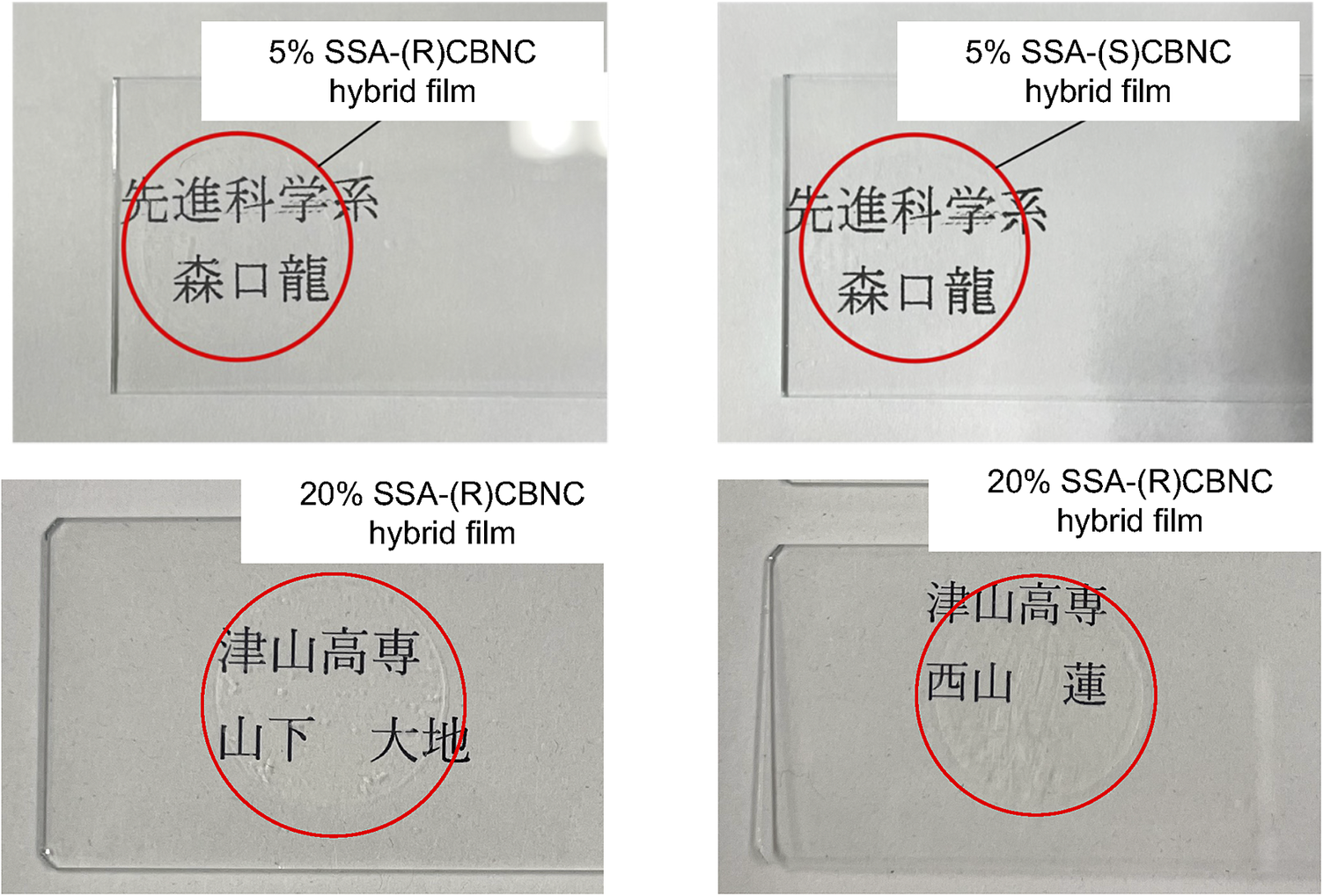
The films obtained with both (R)- and (S)-CBNC and with 5% and 20% CEC were colorless and transparent to the naked eye, with letters clearly visible through each film (Fig. 2).
Photographs of SSA-CBNC hybrid films: 5 and 20% CEC SSA-(R)-CBNC and 5 and 20% CEC SSA-(S)-CBNC. Hybrid films were transferred onto the glass inside the area indicated by the red circle.

Figure 2. Long description
Top left panel shows a glass slide labeled 5 percent S S A dash R dash C B N C hybrid film, with a red circle enclosing Japanese text. Top right panel displays a similar glass slide labeled 5 percent S S A dash S dash C B N C hybrid film, also with a red circle around identical Japanese text. Bottom left panel presents a glass slide labeled 20 percent S S A dash R dash C B N C hybrid film, with a red circle enclosing different Japanese text. Bottom right panel shows another glass slide labeled 20 percent S S A dash R dash C B N C hybrid film, with a red circle around a third set of Japanese text. All hybrid films are visibly transparent, and the red circles indicate the specific regions where the films were transferred onto the glass.
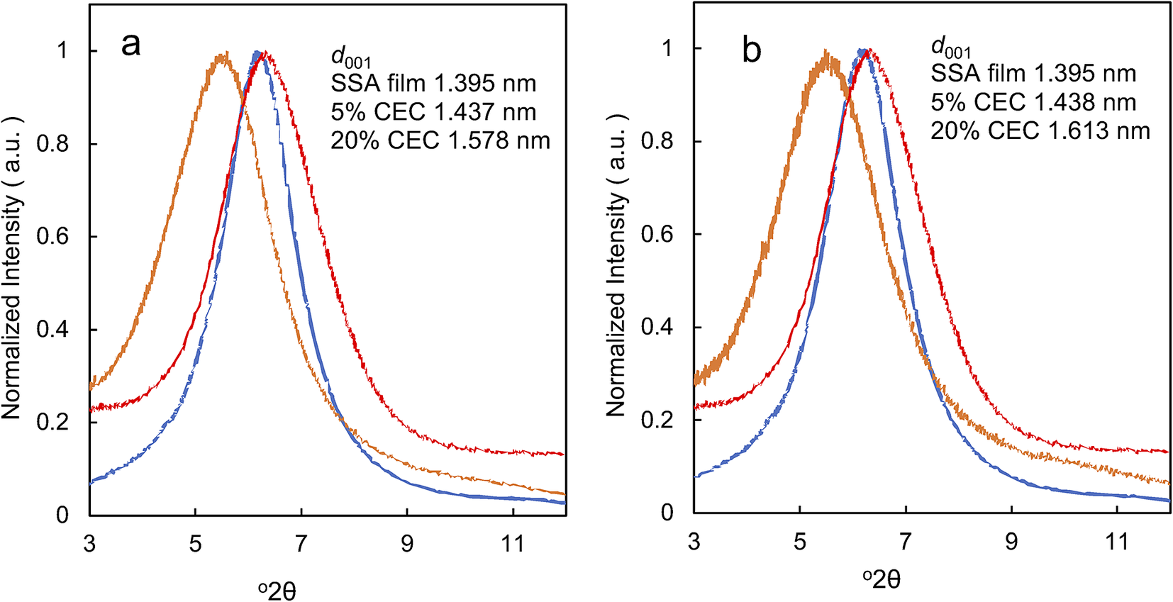
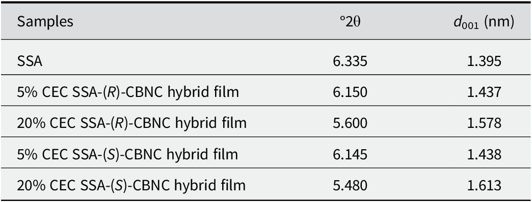
X-ray diffraction was used to characterize the SSA-CBNC hybrid films obtained (Fig. 3). The films transferred onto glass substrates exhibited a face-on orientation of the SSA nanosheets with basal planes parallel to the substrate. Accordingly, the lowest-angle reflection was assigned to the (001) basal reflection of the hybrid. The corresponding d 001 spacing represents the periodic repeat distance normal to the layers, i.e. the distance from one clay sheet to the next across the interlayer space. For both (R)- and (S)-CBNC, the d 001 of the 5% and 20% CEC hybrid films were slightly larger than those of the SSA film (Table 1). This small, systematic increase is consistent with a perturbation of the interlayer environment and may suggest partial incorporation of CBNC into the interlayer space. The d 001 value of the SSA film was 1.395 nm, whereas the 20% CEC hybrid films showed larger d 001 values (1.578 and 1.613 nm), corresponding to an increase of ~0.18–0.22 nm (Fig. 3). This loading-dependent increase is consistent with a perturbation of the interlayer environment and is more suggestive of partial incorporation of CBNC into confined interlayer nanospaces at higher loading. At low dye loadings relative to CEC, basal spacing can be dominated by hydration/solvation of inorganic interlayer cations and may exhibit only subtle changes even when the interlayer environment was perturbed. Therefore, contributions from strongly surface-associated (external-surface and/or edge-site) species cannot be excluded based on XRD alone.
XRD profiles of (a): SSA-(R)-CBNC hybrid film; and (b) SSA-(S)-CBNC hybrid film. The results for the SSA film, 5% CEC hybrid film, and 20% CEC hybrid film are shown using red, blue, and orange lines, respectively.

Figure 3. Long description
Panel a on the left shows normalized intensity on the y axis and 2 theta in degrees on the x axis, ranging from 3 to 11. Three lines are plotted: red for S S A film with d sub 0 0 1 equal to 1.395 nanometers, blue for 5 percent C E C hybrid film with d sub 0 0 1 equal to 1.437 nanometers, and orange for 20 percent C E C hybrid film with d sub 0 0 1 equal to 1.578 nanometers. All lines show a single broad peak between 5 and 6.5 degrees 2 theta, with the peak shifting to lower angles and broadening as C E C increases. Panel b on the right has the same axes and line colors. The red line represents S S A film with d sub 0 0 1 equal to 1.395 nanometers, blue for 5 percent C E C hybrid film with d sub 0 0 1 equal to 1.438 nanometers, and orange for 20 percent C E C hybrid film with d sub 0 0 1 equal to 1.613 nanometers. The trend is similar: the peak shifts to lower angles and broadens as C E C increases. The legend in each panel lists the d sub 0 0 1 values for each sample.
Diffraction angles and values of d 001 for SSA films and SSA-CBNC hybrid films

Table 1. Long description
Column headers from left to right are Samples, degree 2 theta, and d sub 001 in nanometers. The first row lists SSA with 6.335 for degree 2 theta and 1.395 for d sub 001. The second row is 5 percent CEC SSA open parenthesis R close parenthesis CBNC hybrid film with 6.150 for degree 2 theta and 1.437 for d sub 001. The third row is 20 percent CEC SSA open parenthesis R close parenthesis CBNC hybrid film with 5.600 for degree 2 theta and 1.578 for d sub 001. The fourth row is 5 percent CEC SSA open parenthesis S close parenthesis CBNC hybrid film with 6.145 for degree 2 theta and 1.438 for d sub 001. The fifth row is 20 percent CEC SSA open parenthesis S close parenthesis CBNC hybrid film with 5.480 for degree 2 theta and 1.613 for d sub 001. As CEC content increases from 5 percent to 20 percent, degree 2 theta decreases and d sub 001 increases for both R and S chiralities.
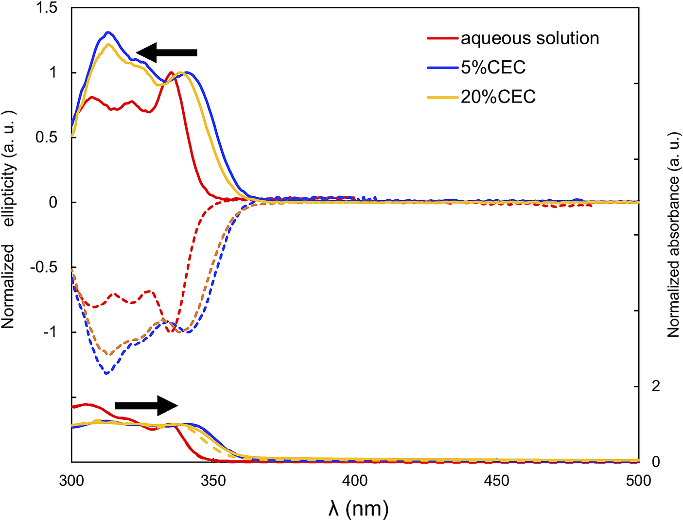
UV-Vis absorption spectra were measured for the films (Fig. 4). The spectra of (R)- and (S)-CBNC had essentially the same shape as expected for an enantiomeric pair in an achiral environment. In such a medium, enantiomers have the same electronic absorption spectra, and their chirality is, instead, manifested in chiroptical properties such as CD and CPL (Setnička et al., Reference Setnička, Urbanová, Bouř, Král and Volka2001; Labuta et al., Reference Labuta, Ishihara, Payne, Takimoto, Sato, Hanyková, Ariga and Hill2021). For all films, the absorption bands appeared at nearly the same wavelengths as in solution, and no additional bands emerged upon hybrid film formation. These observations indicated that CBNC did not form aggregates (e.g. J- or H-aggregates) in SSA-CBNC hybrid films.
CD spectra (upper) and absorption spectra (lower) of SSA-CBNC hybrid films. The results for hybrid films prepared using the (R)- and (S)-enantiomers of CBNC are shown using continuous and dashed lines, respectively. The results for the CBNC aqueous solution, 5% CEC CBNC hybrid film, and 20% CEC CBNC hybrid film are shown using red, blue, and orange lines, respectively.

Figure 4. Long description
The upper panel displays normalized ellipticity in arbitrary units on the y axis versus wavelength in nanometers on the x axis, ranging from 300 to 500. Three color-coded data series are present: red for aqueous solution, blue for 5 percent C E C, and orange for 20 percent C E C. Each series is shown as a solid line for the R enantiomer and a dashed line for the S enantiomer. All curves show pronounced peaks and troughs between 300 and 370 nanometers, with the blue 5 percent C E C solid line reaching the highest positive ellipticity near 320 nanometers, while the dashed lines mirror the solid lines with opposite sign. Beyond 370 nanometers, all lines converge toward zero. The lower panel shows normalized absorbance in arbitrary units on the y axis, with the same color scheme and line styles. All curves exhibit a sharp rise in absorbance between 300 and 350 nanometers, peaking near 330 nanometers, then rapidly decreasing and flattening out above 370 nanometers. The legend at the upper right identifies the color and line style assignments. Black arrows highlight the main spectral features in both panels.
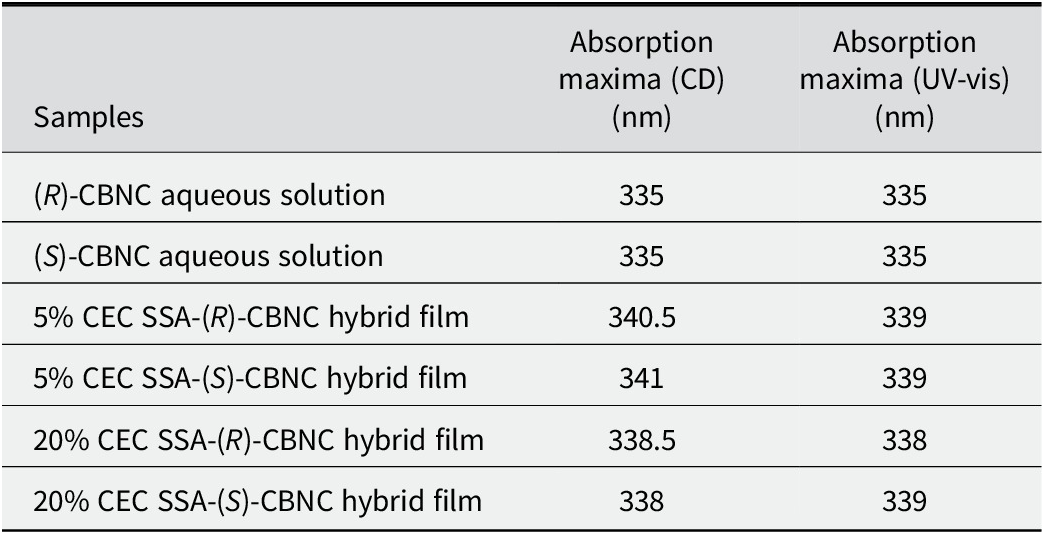
The absorption maxima (λmax; Table 2) of (R)- and (S)-CBNC in aqueous solution were both 335 nm. The absorption maxima of all SSA-CBNC hybrid films were essentially the same, i.e. 338–339 nm. The planarity of organic molecules is known to increase in the interlayer space of clay minerals (Takagi et al., Reference Takagi, Konno, Ishida, Ceklovsky, Masui, Shimada, Tachibana and Inoue2010; Suzuki et al., Reference Suzuki, Tenma, Nishioka, Kamada, Ohta and Kawamata2011; Fernandes and Dey, Reference Fernandes and Dey2025). For the CBNC in the present study, if the small increase in d 001 is taken to suggest partial incorporation into confined interlayer nanospaces, the red shift may be rationalized by: (1) narrowing of the dihedral angle between the two naphthalene units, and (2) increasing the planarity of the biphenyl structure connecting the naphthalene core and the 3,4,5-trifluorophenyl group. Both effects extended the effective π-conjugation, thereby red-shifting the λmax.
Circular dichroism (CD) and ultraviolet-visible (UV-Vis) absorption maxima of the CBNC aqueous solution and SSA-CBNC hybrid films

Table 2. Long description
The table has three columns: Samples, Absorption maxima C D in nanometers, and Absorption maxima U V–vis in nanometers. The first row lists open parenthesis R close parenthesis–C B N C aqueous solution with 335 nanometers for both C D and U V–vis. The second row is open parenthesis S close parenthesis–C B N C aqueous solution, also with 335 nanometers for both methods. The third row is 5 percent C E C S S A–open parenthesis R close parenthesis–C B N C hybrid film, with 340.5 nanometers for C D and 339 nanometers for U V–vis. The fourth row is 5 percent C E C S S A–open parenthesis S close parenthesis–C B N C hybrid film, with 341 nanometers for C D and 339 nanometers for U V–vis. The fifth row is 20 percent C E C S S A–open parenthesis R close parenthesis–C B N C hybrid film, with 338.5 nanometers for C D and 338 nanometers for U V–vis. The sixth row is 20 percent C E C S S A–open parenthesis S close parenthesis–C B N C hybrid film, with 338 nanometers for C D and 339 nanometers for U V–vis.
The CD spectra of (R)- and (S)-CBNC were near-mirror images in both aqueous solution and in the hybrid films (Fig. 4). The CD signals of the SSA-CBNC hybrid films occurred at almost the same wavelength as in the UV-Vis absorption spectra (Fig. 4). In addition, the signs of the CD ellipticity for the SSA-(R)-CBNC and SSA-(S)-CBNC hybrid films were the same as those of the (R)- and (S)-CBNC aqueous solutions, respectively. Together, these observations indicate that the molecular chirality of CBNC was retained even when combined with SSA in the hybrid films, and therefore the SSA-CBNC hybrid films were expected to exhibit CPL.
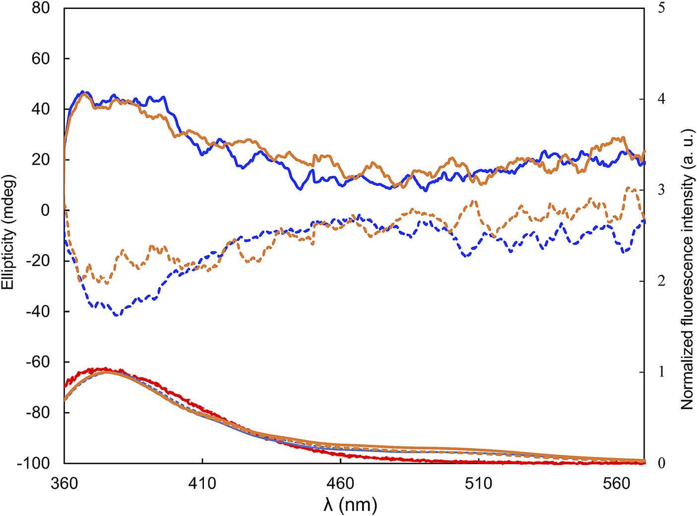
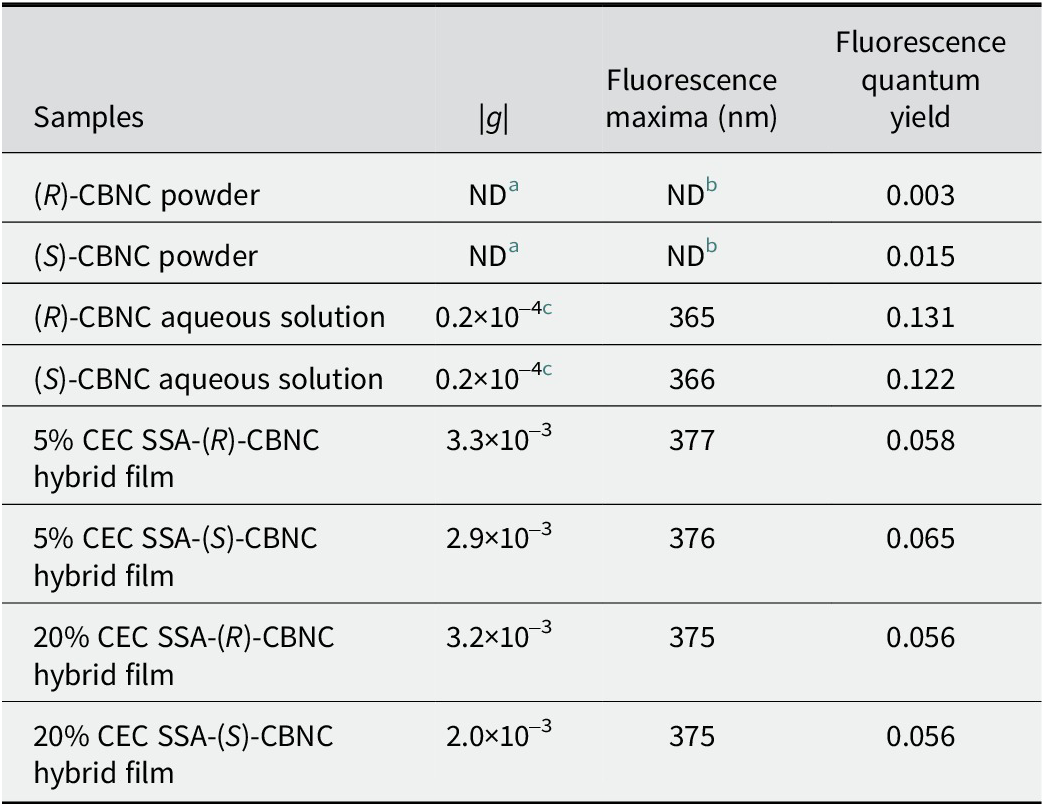
Fluorescence and CPL spectra were also measured (Fig. 5). The efficiency of CPL (represented by the |g| value), fluorescence maxima, and fluorescence quantum yields are summarized in Table 3. The fluorescence maxima of (R)- and (S)-CBNC were 365 and 366 nm, respectively. The fluorescence maxima of all SSA-CBNC hybrid films were essentially the same, namely 375–377 nm. Irrespective of CBNC chirality, fluorescence maxima were red-shifted in the hybrid films relative to the aqueous solutions; this mirrored the red-shift observed in the UV-Vis absorption spectra. For the fluorescence quantum yield, CBNC powder was essentially non-emissive (quantum yield ≤0.015), whereas the hybrid films exhibited fluorescence (quantum yield ≈0.05). These results showed that although CBNC was essentially non-emissive as a neat powder, it produced measurable fluorescence in the clay-organic cation hybrid films, although still at a lower value than for CBNC in solution. Only two loadings (5% and 20% CEC) were examined; therefore, quantitative composition-property trends are not discussed here, which is intended as a proof-of-concept demonstration. Notably, the UV-Vis absorption and fluorescence maxima were essentially the same at the two tested loadings (5% and 20% CEC). Therefore, the following section focuses on the CPL response rather than on loading-dependent trends.
CPL spectra (upper) and fluorescence spectra (lower) of SSA-CBNC hybrid films. The results for the (R)- and (S)-enantiomers are shown using continuous and dashed lines, respectively. The results for the CBNC aqueous solution, 5% CEC CBNC hybrid film, and 20% CEC CBNC hybrid film are shown using red, blue, and orange lines, respectively.

Figure 5. Long description
The x-axis shows wavelength in nanometers from 360 to 560. The left y-axis is ellipticity in millidegrees from minus 100 to 80. The right y-axis is normalized fluorescence intensity from 0 to 5 arbitrary units. The upper section displays C P L spectra with solid lines for R enantiomer and dashed lines for S enantiomer. Red, blue, and orange lines represent C B N C aqueous solution, 5 percent C E C C B N C hybrid film, and 20 percent C E C C B N C hybrid film, respectively. In the C P L spectra, blue and orange lines show higher ellipticity values, with the blue solid line peaking near 40 millidegrees around 370 nanometers, while red lines remain negative throughout. The lower section shows fluorescence spectra, where all lines peak near 370 nanometers, with the red line showing the highest intensity, followed by blue and orange. The dashed lines (S enantiomer) generally mirror the trends of the solid lines (R enantiomer) but with lower or negative ellipticity values. The data illustrate enantiomeric and compositional dependence of both C P L and fluorescence responses.
Dissymmetry factors (|g| values), fluorescence maxima, and fluorescence quantum yields of the CBNC aqueous solution and SSA-CBNC hybrid films

Table 3. Long description
The table has four columns: Samples, absolute g values, fluorescence maxima in nanometers, and fluorescence quantum yield. From top to bottom, the samples are: (R)-C B N C powder with g and maxima not determined, quantum yield 0.003; (S)-C B N C powder with g and maxima not determined, quantum yield 0.015; (R)-C B N C aqueous solution with g 0.2 times 10 to the minus 4, maxima 365, quantum yield 0.131; (S)-C B N C aqueous solution with g 0.2 times 10 to the minus 4, maxima 366, quantum yield 0.122; 5 percent C E C S S A-(R)-C B N C hybrid film with g 3.3 times 10 to the minus 3, maxima 377, quantum yield 0.058; 5 percent C E C S S A-(S)-C B N C hybrid film with g 2.9 times 10 to the minus 3, maxima 376, quantum yield 0.065; 20 percent C E C S S A-(R)-C B N C hybrid film with g 3.2 times 10 to the minus 3, maxima 375, quantum yield 0.056; 20 percent C E C S S A-(S)-C B N C hybrid film with g 2.0 times 10 to the minus 3, maxima 375, quantum yield 0.056. Footnote a: Not determined because the C P L spectrometer is for solutions and thin films, not powders. Footnote b: Not determined because solid samples are almost non-emissive; quantum yields measured but emission maxima not assigned. Footnote c: Value from Kitatobe et al. 2017.
a Not determined (ND) because the CPL spectrometer used in this study is designed for solutions and thin films and cannot be used for powder samples.
b Not determined (ND) because the solid samples were almost non-emissive. Although small quantum yields (0.003 and 0.015) were measured, the emission spectra exhibited very poor signal-to-noise ratios and the emission maximum could not be assigned.
c Value reported by Kitatobe et al. (Reference Kitatobe, Mimura, Tsujimoto, Tajima, Fujiki and Imai2017).
In the CPL spectra of the SSA-CBNC hybrid films, bands occurred at a similar wavelength to the dominant bands in the fluorescence spectra (Fig. 5). These results indicated that the observed CPL signals of the SSA-CBNC hybrid films originated from CBNC emission. The |g| values of aqueous solutions of (R)- and (S)-CBNC are reportedly 0.2×10⁻⁴ (371 nm) and 0.2×10⁻⁴ (371 nm), respectively (Kitatobe et al., Reference Kitatobe, Mimura, Tsujimoto, Tajima, Fujiki and Imai2017). The |g| values of 5% CEC (R)-CBNC, 5% CEC (S)-CBNC, 20% CEC (R)-CBNC, and 20% CEC (S)-CBNC were 3.3×10⁻³ (at 366.5 nm), 2.9×10⁻³ (at 379.5 nm), 3.2×10⁻³ (at 367.5 nm), and 2.0×10⁻³ (at 379.5 nm), respectively. Consistent with the UV-Vis and fluorescence results, the |g| values were also essentially unchanged between the two tested loadings (5% and 20% CEC). These results showed that the |g| values of the hybrid films were greater (by approximately two orders of magnitude) than those in aqueous solution. The |g| values of binaphthyl-type compounds are known to correlate with the excited-state dihedral angle between two naphthalene rings. Takaishi et al. (Reference Takaishi, Matsumoto, Kawataka and Ema2021) reported that an optimum excited-state dihedral angle of ~110° in siloxybinaphthyls maximized the |g| value by minimizing the angle between the electric and magnetic transition dipole moments. By contrast, the dihedral angle of CBNC is ~58.4° in water (ground-state density functional theory) (Kitatobe et al., Reference Kitatobe, Mimura, Tsujimoto, Tajima, Fujiki and Imai2017). The red-shift of absorption maxima observed in UV-Vis spectra upon film formation may suggest conformational restriction of CBNC (e.g. increased molecular planarity) relative to aqueous solution. Consequently, even with confinement, the angle probably remains far from the ~110° optimum excited-state dihedral angle reported for siloxybinaphthyls. Nevertheless, an increase in the |g| value was observed for CBNC in the films compared with that in aqueous solution. This change is tentatively ascribed to differences in the π-conjugated system; CBNC contains a trifluorophenyl substituent, which alters the orientation and coupling of the electric and magnetic transition dipole moments relative to those in siloxybinaphthyls. Thus, the ‘best-angle’ identified for siloxybinaphthyls may not be transferable to CBNC. However, the excited-state geometry is not determined directly in the present study, and therefore any discussion of dihedral-angle effects is presented as a plausible hypothesis. Overall, the spectroscopic parameters exhibited little dependence on loading level of CBNC between the two tested loadings (5–20% CEC). The absorption maxima (338–339 nm), fluorescence maxima (375–377 nm), |g| values (3.2–3.3×10⁻³), and fluorescence quantum yields (0.056–0.058) were essentially the same. Therefore, the present discussion focuses on qualitative features of the CPL-active films rather than on quantitative loading-dependent trends.
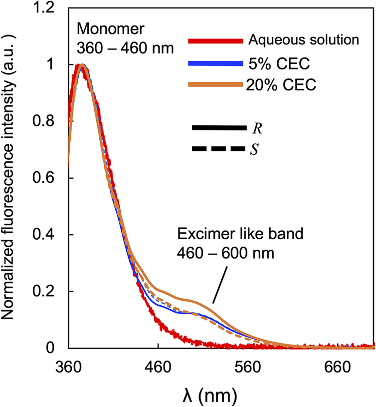
Next, the advantages of fabricating CPL-active materials using a clay-organic cation hybrid system are considered. Fluorescence spectra of aqueous solutions of CBNC and the SSA-CBNC hybrid films were recorded (Fig. 6). In the CBNC-SSA hybrid films, an emission band was observed at 360–460 nm, which was in the same position as that for CBNC in aqueous solution. This band was assigned to monomer emission of CBNC. In the spectra of the hybrid films, a red-shifted emission band appeared at 460–600 nm which was absent from spectra of CBNC in solution. Organic molecules within the interlayer spaces of clays can sometimes exist at local number densities far greater than those in bulk solution. Under such conditions, even luminophores that do not exhibit excimer emission in solution can display excimer emission when present in the interlayer (Tominaga et al., Reference Tominaga, Oniki, Mochida, Kasatani, Tani, Suzuki and Kawamata2016). On the basis of this knowledge, the additional emission band observed for the hybrid films at 460–600 nm could be assigned to excimer emission from CBNC. The |g| value of CPL assigned to excimer emission is known to be larger than that attributed to monomer emission (Inouye et al., Reference Inouye, Hayashi, Yonenaga, Itou, Fujimoto, Uchida, Iwamura and Nozaki2014; Takaishi et al., Reference Takaishi, Iwachido, Takehana, Uchiyama and Ema2019; Zhang et al., Reference Zhang, Li, Geng, Zheng, Quan and Cheng2022). Thus, clay-organic cation hybrids are attractive not only because they can be processed into optically transparent thin films via an aqueous route, but also because the interlayer environment can be engineered to deliberately promote excimer formation and thereby enhance the CPL response. The mechanistic origins of the CPL enhancement and its dependency on the CEC content and interlayer spacing are beyond the scope of this study and will be addressed in future work.
Fluorescence spectra of SSA-CBNC hybrid films. The results for the (R)- and (S)-enantiomers of CBNC are shown using continuous and dashed lines, respectively. The results for the CBNC aqueous solution, 5% CEC CBNC hybrid film, and 20% CEC CBNC hybrid film are shown using red, blue, and orange lines, respectively.

Figure 6. Long description
The x axis is labeled lambda in nanometers, spanning 360 to 660. The y axis is normalized fluorescence intensity in arbitrary units, ranging from 0 to 1.2. Three sample types are shown: aqueous solution (red), 5 percent C E C hybrid film (blue), and 20 percent C E C hybrid film (orange). Each sample is plotted for R enantiomer (solid line) and S enantiomer (dashed line). All spectra show a strong monomer peak between 360 and 460 nanometers, with the highest intensity near 1.0. Beyond 460 nanometers, intensity decreases and a broad excimer-like band appears from 460 to 600 nanometers, more pronounced in the hybrid films, especially at 20 percent C E C. The aqueous solution shows the lowest excimer band. Differences between R and S enantiomers are subtle but visible in the excimer region. The legend at top right identifies line colors and styles. Text annotations mark the monomer region and excimer-like band.
Conclusions
Clay-organic cation hybrid films were fabricated with the binaphthyl derivative CBNC. Optically transparent, CPL-active thin films were obtained by vacuum filtration of the aqueous SSA-CBNC hybrid dispersions. Although CBNC is essentially non-emissive as a neat powder, it became emissive and CPL-active in the clay-based films. The CPL |g| value of CBNC in the hybrid films was greatly enhanced relative to that of CBNC in aqueous solution. The mechanistic origin of this enhancement is not directly resolved here; however, it is proposed that clay association (including possible interlayer involvement) can restrict conformational freedom and/or modify the effective π-conjugation (e.g. via a change in the dihedral angle of CBNC), thereby altering the coupling of electric and magnetic transition dipole moments and enhancing CPL. Overall, this work provides a proof-of-concept that utilizing clay minerals can potentially function as a physical conformational regulator to enable active control of the molecular conformation and chiral response without synthetic modification of the chromophore’s molecular framework. In contrast to the conventional emphasis on molecular design and crystal engineering for improving organic CPL materials, the present work shows that layered inorganic hosts, specifically smectite clays, offer an effective complementary route for designing CPL materials.
Data availability statement
The data supporting the findings of this study are available within the article and from the corresponding author upon reasonable request.
Author contribution
Hiroki Moritomo: Conceptualization, Project administration, Supervision, Data interpretation, Writing – original draft, Writing – review & editing.R. Moriguchi, D. Yamashita, and R. Nishiyama: Investigation, Formal analysis. All authors reviewed and approved the final manuscript.
Acknowledgements
CPL spectra were recorded using the CPL-200 instrument at the Natural Science Center for Basic Research and Development (N-BARD), Hiroshima University, Japan. The authors thank J. Kawamata of Yamaguchi University for measurement of the CD spectra. They are also grateful to Gabrielle David, of Edanz (https://jp.edanz.com/ac), for editing a draft of this manuscript.
Financial support
This work was supported by the Wesco Scientific Promotion Foundation.
Competing interests
The authors declare none.